EP1736340B1 - Cabrioletfahrzeug mit einer Trennwand - Google Patents
Cabrioletfahrzeug mit einer Trennwand Download PDFInfo
- Publication number
- EP1736340B1 EP1736340B1 EP06012829A EP06012829A EP1736340B1 EP 1736340 B1 EP1736340 B1 EP 1736340B1 EP 06012829 A EP06012829 A EP 06012829A EP 06012829 A EP06012829 A EP 06012829A EP 1736340 B1 EP1736340 B1 EP 1736340B1
- Authority
- EP
- European Patent Office
- Prior art keywords
- convertible
- sheet
- luggage space
- separating wall
- convertible top
- Prior art date
- Legal status (The legal status is an assumption and is not a legal conclusion. Google has not performed a legal analysis and makes no representation as to the accuracy of the status listed.)
- Not-in-force
Links
- 238000004804 winding Methods 0.000 claims description 7
- 230000002787 reinforcement Effects 0.000 claims description 5
- 230000004308 accommodation Effects 0.000 claims 1
- 238000012544 monitoring process Methods 0.000 claims 1
- 239000011888 foil Substances 0.000 abstract description 4
- 238000005192 partition Methods 0.000 description 20
- 239000000463 material Substances 0.000 description 4
- 238000011161 development Methods 0.000 description 2
- 230000018109 developmental process Effects 0.000 description 2
- 238000012546 transfer Methods 0.000 description 2
- 230000002411 adverse Effects 0.000 description 1
- 238000013459 approach Methods 0.000 description 1
- 238000013461 design Methods 0.000 description 1
- 239000004816 latex Substances 0.000 description 1
- 229920000126 latex Polymers 0.000 description 1
- 238000000034 method Methods 0.000 description 1
- 230000000414 obstructive effect Effects 0.000 description 1
- 239000000725 suspension Substances 0.000 description 1
- XLYOFNOQVPJJNP-UHFFFAOYSA-N water Substances O XLYOFNOQVPJJNP-UHFFFAOYSA-N 0.000 description 1
Images


Classifications
-
- B—PERFORMING OPERATIONS; TRANSPORTING
- B60—VEHICLES IN GENERAL
- B60J—WINDOWS, WINDSCREENS, NON-FIXED ROOFS, DOORS, OR SIMILAR DEVICES FOR VEHICLES; REMOVABLE EXTERNAL PROTECTIVE COVERINGS SPECIALLY ADAPTED FOR VEHICLES
- B60J7/00—Non-fixed roofs; Roofs with movable panels, e.g. rotary sunroofs
- B60J7/20—Vehicle storage compartments for roof parts or for collapsible flexible tops
- B60J7/207—Vehicle storage compartments for roof parts or for collapsible flexible tops being adjustable in volume, i.e. collapsible in order to increase luggage space in boot when roof is not stored
Definitions
- the DE 101 38 669 A1 discloses a convertible top compartment which has a floor which divides the convertible top storage compartment from a luggage compartment of the vehicle, the convertible compartment compartment floor having at least one adjustable area for volume change of the convertible top compartment and the luggage compartment.
- the adjustable range is formed by a limp but tensile material web, the or the main surface area is displaced by means of a lifting device between the deep top shelf position and the high luggage space Nutz- position.
- the DE 202 09 924 U1 discloses a convertible top compartment, which has a separating device which delimits an additional space at least regionally, and a transfer device, by means of which the separating device between a convertible top position and a luggage receiving position is movable, wherein the separating device comprises a pliable, tensile material web.
- the transfer device includes a tension roller for the material web.
- a guide device is provided for guiding the tensioning roller between a front, in the direction of travel, upper first position and a rear, in the direction of travel, lower second position, guides are each pivotally arranged at the rear end in the direction of travel.
- the tensioner is driven manually, electrically or hydraulically by a rotating Bowden cable.
- the EP 0 860 312 A discloses a variable receiving compartment with two, via an adjustable partition volume-variable storage spaces.
- the partition wall is displaceable to a lowered state when the vehicle roof is opened.
- the adjustment between a superscript and subsided state is motor or mechanical.
- the DE 196 36 027 C1 discloses a partition for dividing a rear storage compartment of a vehicle, which is collapsible to adapt to increased storage space in a space-saving non-use position, wherein the partition is designed as a flexible roller blind.
- the roller blind When it is wound up, the roller blind can be grabbed by a drop rod and pulled further out of the roller blind housing to the rear. While maintaining the tensile forces on the drop rod, this can be manually hang with its end in two suspension abutment.
- the DE 101 04 333 A1 discloses a convertible vehicle with a roof which can be placed in a convertible top compartment, the convertible top compartment being divisible by a variable separating device, which contains at least one movable plate body.
- the plate body is vertically movable via, for example, designed as electric or pneumatic motors lateral drives or manual operation and remains during this movement in its horizontal position.
- the object of the invention is to develop a generic Cabriolet vehicle such that the partition is easy to handle, with the roof closed does not affect the luggage volume and only slightly increased with the top open space requirements, and by a simple and elementary design no devices for lifting and holding the Partition wall to be needed.
- the invention provides a simple and cost-effective way to fully utilize the luggage compartment of a convertible vehicle with the top down, without disturbing structures protrude into the luggage compartment.
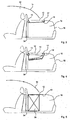
- FIG. 1 illustrated closed convertible vehicle has in the front region of a luggage compartment 16 designed as an elastic film 10 partition below a top cover 12, which delimits the underlying luggage compartment 16 upwards.
- the elastic film 10 is fastened with its front edge to an upper edge of a front luggage compartment partition wall 34 and with its rear edge to a transverse reinforcement 17, which extends transversely across the luggage compartment 16.
- the film 10 In the closed state of the top 14, the film 10 extends substantially flat below the top cover 12.
- the elastic film 10, which consists for example of a highly elastic latex material, is advantageously biased during assembly so that they are closed Condition of the top 14 the flat shape according to Fig. 1 accepts.
- the foil 10 may be e.g. along at least part of its edge with eyelets, which may be formed into suitable projections, e.g. located on the front luggage compartment partition 34 and the upper transverse reinforcement 17 of the luggage compartment 16 are suspended under bias of the film 10.
- the film 10 Because of its small thickness, the film 10 has only a minimal intrinsic volume, so that it does not affect the luggage compartment 16 when the top 14 is closed. Furthermore, it can bulge upwards due to its elasticity and thus can cling to the underside of the top cover 12, as in Fig. 5 when loaded with a large piece of luggage 26 is shown.
- Fig. 2 shows a convertible vehicle in the open state, ie with folded and stowed hood 14th
- the top 14 is folded in a conventional manner such that the top cover 12 can be pivoted upwards in an approximately vertical position.
- the top 14 is then lowered against the elastic film 10 and lowered together with her in the luggage compartment into it.
- the top cover 12th brought back into its initial position with the luggage compartment flap 18 flush and closes a receiving compartment of the top 14 formed by the deformed film 10.
- top cover 12 is a component not necessary for the function of the partition or film 10.
- the drive required to open the top 14 can be switched off.
- the elastic partition 10 then presses the top then advantageously from below against the top cover 12.
- the elastic film 10 ensures that any free space or games, the top 14 are eliminated and the top is rattling recorded.
- the top is folded as far as possible, so that the remaining luggage space 16 remains as large as possible.
- the elastic film can be attached to the vehicle in a further embodiment, for example by means of a zipper, a screwed frame, or otherwise watertight, so that no water can get into the luggage compartment 16, when the convertible top 12 is not watertight.
- the dividing wall can be replaced by a windable film 10, which does not necessarily have to be elastically extensible.
- a winding shaft 13 not described in detail, for example, on the luggage compartment partition wall 34, as in Fig. 3 shown to be attached.
- the other end of the partition 10 may, as in the described embodiment by means of eyelets located on it to be attached to suitable projections on a transverse reinforcement 17 of the luggage compartment 16.
- the winding shaft 13, the film 10 is biased biased in the closed position of the top 14.
- the film is unrolled from the winding shaft 13 and receives the top 14 to be stowed away. If the top 14 is closed again, the film is rolled up again by the winding shaft 13 and held biased in the closed position of the top 14.
- FIGS. 6 to 8 A development of the embodiments described above is in the FIGS. 6 to 8 illustrated, in which at least one stationary mounted in the luggage compartment 16 sensor 28 the area that the top 14 in its collapsed state requires (hereinafter called sensor area 30) checked for the presence of objects.
- sensor area 30 the area that the top 14 in its collapsed state requires
- a mounted on the luggage compartment partition 34 sensor 28 is shown.
- a large piece of luggage 22 located in the luggage compartment 16 protrudes into the sensor area 30.
- the sensor 28 detects an obstacle in the area of the top 14 to be stowed and gives a corresponding control signal to a control unit (not shown).
- This control unit can block, for example, the opening of the top 14 and give the vehicle operator a corresponding signal that the top 14 is not without Damage to the top 14 or the luggage compartment 22 located in the luggage compartment 22 is possible.
- Fig. 7 shows a lower piece of luggage 24, which is located below the sensor area 30 and thus allows an opening of the top 14.
- the sensor 28 would transmit to the control unit a signal that the sensor area 30 is free of objects.
- one or more proximity or touch sensors may be attached to the film 10. If during the opening of the top 14, an improper approach to or contact with an object takes place, a signal can be supplied to a control unit which controls the operation of opening the top, e.g. stops.
- force sensors can interrupt the opening process if the force required for the top opening is too great.
- the force can be determined by the power consumption of a top opening actuator.
Landscapes
- Engineering & Computer Science (AREA)
- Mechanical Engineering (AREA)
- Vehicle Step Arrangements And Article Storage (AREA)
- Body Structure For Vehicles (AREA)
- Seal Device For Vehicle (AREA)
Description
- Die
DE 101 38 669 A1 offenbart einen Verdeckkasten, welcher einen Boden aufweist, der den Verdeck- Aufnahmeraum von einem Gepäckraum des Fahrzeugs abteilt, wobei der Verdeckkastenboden zumindest einen verstellbaren Bereich zur Volumenveränderung des Verdeckkastens und des Gepäckraumes aufweist. Der verstellbare Bereich ist von einer biegeschlaffen, jedoch zugfesten Materialbahn gebildet, die bzw. deren Hauptflächenbereich mittels einer Hubeinrichtung zwischen der tiefen Verdeckablage- Position und der hohen Gepäckraum- Nutz- Position verlagerbar ist. - Die
DE 202 09 924 U1 offenbart einen Verdeckkasten, welcher eine Trennvorrichtung, die einen Zusatzraum zumindest bereichsweise abgrenzt, und eine Überführeinrichtung aufweist, mittels derer die Trennvorrichtung zwischen einer Verdeckaufnahmestellung und einer Gepäckaufnahmestellung bewegbar ist, wobei die Trennvorrichtung eine biegeschlaffe, zugfeste Materialbahn umfasst. Die Überführeinrichtung enthält eine Spannrolle für die Materialbahn. Eine Führungseinrichtung ist zum Führen der Spannrolle zwischen einer in Fahrtrichtung vorderen, oberen ersten Position und einer in Fahrtrichtung hinteren, unteren zweiten Position vorgesehen, wobei Führungen jeweils an deren in Fahrtrichtung hinterem Ende schwenkbar angeordnet sind. Die Spannrolle wird mit einem umlaufenden Bowdenzug manuell, elektrisch oder hydraulisch angetrieben. - Die
EP 0 860 312 A offenbart ein variables Aufnahmefach mit zwei, über eine verstellbare Trennwand volumenveränderlichen Ablageräumen. Die Trennwand ist in einen tiefgestellten Zustand versetzbar, wenn das Fahrzeugdach geöffnet wird. Die Verstellung zwischen einem hochgestellten und tiefgestellten Zustand erfolgt motorisch oder mechanisch. - Die
DE 196 36 027 C1 offenbart eine Trennwand zum Unterteilen eines Heckstauraums eines Fahrzeugs, die zur Anpassung an einen erhöhten Stauraumbedarf in eine platzsparende Nichtgebrauchsstellung zusammenlegbar ist, wobei die Trennwand als flexible Rollobahn ausgebildet ist. Die Rollobahn lässt sich im aufgewickelten Zustand an einem Fallstab ergreifen und nach hinten weiter aus dem Rollogehäuse herausziehen. Unter Aufrechterhaltung der Zugkräfte am Fallstab lässt sich dieser händisch mit seinen Endbereichen in zwei Einhängungswiderlager einhängen. - Die
DE 101 04 333 A1 offenbart ein Cabriolet- Fahrzeug mit einem in einem Verdeckkasten ablegbaren Dach, wobei der Verdeckkasten durch eine variable Trennvorrichtung abteilbar ist, die zumindest einen beweglichen Plattenkörper enthält. Der Plattenkörper ist über beispielsweise als Elektro- oder als Pneumatikmotoren ausgebildete seitliche Antriebe oder über manuelle Betätigung vertikal beweglich und verbleibt während dieser Bewegung in seiner horizontalen Lage. - Aufgabe der Erfindung ist es, ein gattungsgemäßes Cabrioletfahrzeug derart weiterzubilden, dass die Trennwand einfach handhabbar ist, bei geschlossenem Verdeck das Gepäckvolumen nicht beeinträchtigt und bei geöffnetem Verdeck dessen Platzbedarf nur unwesentlich vergrößert, und durch eine einfache und elementare Bauweise keine Vorrichtungen zum Anheben und Halten der Trennwand benötigt werden.
- Die Aufgabe wird mit einem Cabrioletfahrzeug nach Anspruch 1 gelöst.
- Die Unteransprüche sind auf vorteilhafte Ausführungsformen und Weiterbildungen der erfindungsgemäßen Trennwand gerichtet.
- Insgesamt wird mit der Erfindung eine einfache und kostengünstige Möglichkeit geschaffen, den Gepäckraum eines Cabrioletfahrzeugs bei geschlossenem Verdeck voll zu nutzen, ohne dass störende Strukturen in den Gepäckraum hineinstehen.
- Die Erfindung wird im Folgenden anhand schematischer Zeichnungen beispielsweise und in weiteren Einzelheiten anhand bevorzugter Ausführungsformen erläutert.
- In den
Figuren 1 - 8 stellen dar: - Fig. 1
- einen Teillängsschnitt eines Cabrioletfahrzeugs mit einer erfindungsgemäßen Trennwand bei geschlossenem Verdeck,
- Fig. 2
- einen Teillängsschnitt eines Cabrioletfahrzeugs gemäß
Fig. 1 bei offenem Verdeck, - Fig. 3
- einen Teillängsschnitt eines Cabrioletfahrzeugs mit einer durch eine Wickelwelle vorgespannten Trennwand bei geschlossenem Verdeck,
- Fig. 4
- einen Teillängsschnitt des Cabrioletfahrzeugs gemäß
Fig. 3 bei offenem Verdeck, - Fig. 5
- einen Teillängsschnitt eines Cabrioletfahrzeugs bei geschlossenem Verdeck mit einem hohen Gepäckstück im Gepäckraum,
- Fig. 6
- einen Teillängsschnitt eines Cabrioletfahrzeugs bei geschlossenem Verdeck mit einem großen Gepäckstück im Gepäckraum,
- Fig. 7
- einen Teillängsschnitt eines Cabrioletfahrzeugs bei geschlossenem Verdeck mit einem kleinerem als in
Fig. 6 gezeigtem Gepäckstück im Gepäckraum, - Fig. 8
- einen Teillängsschnitt eines Cabrioletfahrzeugs bei offenem Verdeck mit einem gegenüber
Fig. 7 kleinerem Gepäckstück im Gepäckraum; - Das in
Fig. 1 dargestellte geschlossene Cabrioletfahrzeug weist im vorderen Bereich eines Gepäckraums 16 eine als elastische Folie 10 ausgebildete Trennwand unterhalb eines Verdeckdeckels 12 auf, die den darunter liegenden Gepäckraum 16 nach oben abgrenzt. Die elastische Folie 10 ist mit ihrem Vorderrand an einem Oberrand einer vorderen Gepäckraumtrennwand 34 und mit ihrem Hinterrand an einer Querversteifung 17 befestigt, die quer über den Gepäckraum 16 verläuft. - Im geschlossenen Zustand des Verdecks 14 erstreckt sich die Folie 10 im Wesentlichen flach unterhalb des Verdeckdeckels 12. Die elastische Folie 10, die beispielsweise eine aus einem hochelastischen Latexmaterial besteht, wird bei der Montage vorteilhafterweise vorgespannt, damit sie im geschlossenen Zustand des Verdecks 14 die flache Form gemäß
Fig. 1 annimmt. - Für eine einfache Montage und Demontage kann die Folie 10 z.B. längs zumindest eines Teils ihres Randes mit Ösen versehenen sein, die in geeignete Vorsprünge, die sich z.B. an der vorderen Gepäckraumtrennwand 34 und an der oberen Querversteifung 17 des Gepäckraumes 16 befinden, unter Vorspannung der Folie 10 eingehängt werden.
- Wegen ihrer geringen Dicke hat die Folie 10 nur ein minimales Eigenvolumen, so dass sie bei geschlossenem Verdeck 14 den Gepäckraum 16 nicht beeinträchtigt. Weiterhin kann sie sich aufgrund ihrer Elastizität nach oben wölben und kann sich somit an die Unterseite des Verdeckdeckels 12 anschmiegen, wie dies in
Fig. 5 bei Beladung mit einem hohen Gepäckstück 26 dargestellt ist. - Bei geschlossenem Verdeck steht dem Fahrzeugbenutzer somit der Gepäckraum 16 nahezu vollständig zur Verfügung, da dieser weder durch die Trennwand, noch durch die Befestigung der Trennwand in seiner Größe beeinträchtigt wird.
-
Fig. 2 zeigt ein Cabrioletfahrzeug im offenen Zustand, d.h. mit zusammengefaltetem und verstautem Verdeck 14. - Um das Verdeck in diesen Zustand zu überführen, wird zunächst der hintere Teil des Verdecks 14 in an sich bekannter Weise derart nach oben geklappt, dass der Verdeckdeckel 12 nach oben in eine etwa senkrechte Stellung geschwenkt werden kann. Durch einen nicht näher beschriebenen Mechanismus wird das Verdeck 14 dann gegen die elastische Folie 10 abgesenkt und zusammen mit ihr in den Gepäckraum hinein abgesenkt. Nach vollständigem Öffnen und Zusammenfalten des Verdecks 14 in die in
Fig. 2 gezeigte Stellung wird der Verdeckdeckel 12 wieder in seine mit der Gepäckraumklappe 18 bündige Ausgangsstellung gebracht und schließt ein durch die verformte Folie 10 gebildetes Aufnahmefach des Verdecks 14. - Es versteht sich, dass der Verdeckdeckel 12 ein zur Funktion der Trennwand bzw. Folie 10 nicht notwendiges Bauteil ist.
- Nach Absenken des Verdecks 14 gegen die Trennwand 10 und Schließen und Verriegeln des Verdeckdeckels 12, kann der zum Öffnen des Verdecks 14 benötigte Antrieb abgeschaltet werden. Die elastische Trennwand 10 drückt das Verdeck dann vorteilhafterweise von unten gegen den Verdeckdeckel 12. Damit gewährleistet die elastische Folie 10, dass eventuelle Freiräume bzw. Spiele, des Verdecks 14 beseitigt werden und das Verdeck klapperfrei aufgenommen ist. Das Verdeck ist weitetmöglich zusammengelegt, so dass der verbleibende Gepäckraum 16 so groß wie möglich bleibt.
- Die elastische Folie kann in einer weiteren Ausführungsform, beispielsweise mittels eines Reißverschlusses, eines verschraubten Rahmens, oder sonstwie wasserdicht an dem Fahrzeug angebracht werden, so dass kein Wasser in den Gepäckraum 16 gelangen kann, wenn der Verdeckdeckel 12 nicht wasserdicht abschließt.
- In einer weiteren Ausführungsform kann die Trennwand durch eine aufwickelbare Folie 10 ersetzt werden, die nicht zwingend elastisch dehnbar sein muss. Hierzu kann eine nicht näher beschriebene Wickelwelle 13 z.B. an der Gepäckraumtrennwand 34, wie in
Fig. 3 gezeigt, befestigt sein. Das andere Ende der Trennwand 10 kann, wie bei der geschilderten Ausführungsform mittels an ihr befindlichen Ösen an geeignete Vorsprünge an einer Querversteifung 17 des Gepäckraumes 16 befestigt sein. Günstigerweise wird die Wickelwelle 13 die Folie 10 in der Schließstellung des Verdecks 14 vorgespannt halten. - Wird das Verdeck 14 geöffnet und in den Gepäckraum 16 hinein bewegt so wird die Folie von der Wickelwelle 13 abgerollt und nimmt das zu verstauenden Verdeck 14 auf. Wird das Verdeck 14 wieder geschlossen, so wird die Folie durch die Wickelwelle 13 wieder aufgerollt und in der Schließstellung des Verdecks 14 vorgespannt gehalten.
- Eine Weiterbildung der oben beschriebenen Ausführungsformen wird in den
Figuren 6 bis 8 dargestellt, bei denen mindestens ein ortsfest im Gepäckraum 16 angebrachter Sensor 28 den Bereich den das Verdeck 14 in seinem zusammengelegten Zustand benötigt(im folgenden Sensorbereich 30 genannt) auf Vorhandensein von Gegenständen überprüft. Bei motorisch geöffnetem Verdeck kann auf diese Weise abgefragt werden, ob ein beschädigungsloses Öffnen des Verdecks 14 möglich ist. Im Falle, dass sich Gegenstände in dem Bereich befinden, der für das Verstauen des Verdecks 14 benötigt wird, wird das motorische Öffnen dann beispielsweise verweigert. - Auch bei manuell betätigten Verdecken ist ein Einsatz von Sensoren sinnvoll, da der Fahrzeugbediener z.B. durch eine Warnleuchte oder ein akustisches Signal vor hinderlichen Gegenständen im betreffenden Bereich des Gepäckraums 16 gewarnt werden kann, ohne dass der Gepäckraum 16 vor dem Öffnen des Verdecks überprüft werden muss.
- In der
Fig. 6 ist ein an der Gepäckraumtrennwand 34 angebrachter Sensor 28 dargestellt. Ein im Gepäckraum 16 befindliches großes Gepäckstück 22 ragt in den Sensorbereich 30 hinein. Bei dieser Anordnung erkennt der Sensor 28 ein Hindernis im Bereich des zu verstauenden Verdecks 14 und gibt ein entsprechendes Steuersignal an eine Kontrolleinheit (nicht dargestellt). Diese Kontrolleinheit kann z.B. das Öffnen des Verdecks 14 blockieren und den Fahrzeugbediener ein entsprechendes Signal geben, dass das Verdeck 14 nicht ohne Beschädigung des Verdecks 14 oder des im Gepäckraum 16 befindlichen Gepäckstücks 22 möglich ist. -
Fig. 7 zeigt ein niedrigeres Gepäckstück 24, das sich unterhalb des Sensorbereichs 30 befindet und somit ein Öffnen des Verdecks 14 zulässt. Hierbei würde der Sensor 28 der Kontrolleinheit ein Signal übermitteln, dass der Sensorbereich 30 frei von Gegenständen ist. - Bei einer weiteren Ausführungsform können ein oder mehrere Annäherungs- oder Berührungssensoren an der Folie 10 angebracht werden. Wenn während des Öffnens des Verdecks 14, eine unzulässige Annäherung an oder Berührung mit einem Gegenstand erfolgt, kann ein Signal an eine Kontrolleinheit geliefert werden, die den Vorgang des Öffnens des Verdecks z.B. stoppt.
- Alternativ können Kraftsensoren bei zu großem Kraftaufwand bei der Verdecköffnung den Öffnungsprozess unterbrechen. Die Kraft kann durch die Stromaufnahmen eines des verdecköffnenden Aktors festgestellt werden.
-
- 10
- Folie
- 12
- Verdeckdeckel
- 13
- Wickelwelle
- 14
- Verdeck
- 16
- Gepäckraum
- 17
- Querversteifung
- 18
- Gepäckraumklappe
- 22
- großes Gepäckstück
- 24
- kleines Gepäckstück
- 26
- hohes Gepäckstück
- 28
- Sensor
- 30
- Sensorbereich
- 34
- wand
Claims (8)
- Cabrioletfahrzeug enthaltend,
einen im Heck angeordneten Gepäckraum (16), dessen vorderer Bereich nach oben durch eine Trennwand (10) abgeschlossen ist, und
ein Verdeck (14), das sich beim Öffnen zusammen mit der Trennwand (10) in den oberen, vorderen Bereich des Gepäckraums (16), hinein bewegt, so dass die Trennwand (10) unter Verkleinerung des Gepäckraums (16) bei voll geöffnetem Verdeck (14) ein vom Gepäckraum (16) getrenntes Aufnahmefach für das zusammengelegte Verdeck (14) bildet und bei geschlossenem Verdeck (14) den in seiner Größe voll nutzbaren Gepäckraum (16) nach oben hin zum Fahrzeuginnenraum abschließt,
dadurch gekennzeichnet,
dass die Trennwand durch eine in ihre Lage bei geschlossenem Verdeck (14) elastisch vorgespannte verformbare Folie gebildet ist, die durch Anlage an dem beim Öffnen in den vorderen oberen Bereich des Gepäckraums (16) hinein bewegten Verdeck unter Vergrößerung ihrer Fläche in ihre Lage bei voll geöffnetem Verdeck bewegt wird und beim Schließen des Verdecks aufgrund ihrer Vorspannung selbständig in ihre Lage beim geschlossenen Verdeck zurückkehrt. - Cabrioletfahrzeug nach Anspruch 1,
dadurch gekennzeichnet,
dass die Folie (10) zumindest an ihrem vorderen und hinteren Rand am Fahrzeug befestigt und in sich elastisch dehnbar ist. - Cabrioletfahrzeug nach Anspruch 1 oder 2,
dadurch gekennzeichnet,
dass die Folie (10) längs ihres Umfangs wasserdicht mit dem Fahrzeug verbunden ist. - Cabrioletfahrzeug nach Anspruch 1 oder 2,
dadurch gekennzeichnet,
dass die Folie (10) an ihrem vorderen oder hinteren Rand auf einer die Folie (10) vorspannenden Wickelwelle aufgewickelt ist. - Cabrioletfahrzeug nach einem der Ansprüche 1 bis 4,
dadurch gekennzeichnet,
dass ein vorderer Rand der Folie (10) am Oberrand einer den Gepäckraum (16) in Fahrzeuglängsrichtung vom Innenraum des Fahrzeugs trennenden Wand (34) befestigt ist. - Cabrioletfahrzeug nach einem der Ansprüche 1 bis 4,
dadurch gekennzeichnet,
dass ein Hinterrand der Folie (10) an einer oberen Querversteifung des Gepäckraums (16) befestigt ist. - Cabrioletfahrzeug nach einem der Ansprüche 1 bis 6,
gekennzeichnet durch wenigstens einen Sensor (28) zum Überprüfen, ob der von Trennwand (10) beim Öffnen des Verdecks (14) überstrichene Bereich frei von Gegenständen ist. - Cabrioletfahrzeug nach einem der Ansprüche 1 bis 7,
gekennzeichnet durch wenigstens einen an der Trennwand (10) angebrachten Sensor (28) zum Erfassen einer Kollision der Trennwand (10) mit Gegenständen im Gepäckraum (16).
Applications Claiming Priority (1)
| Application Number | Priority Date | Filing Date | Title |
|---|---|---|---|
| DE102005029693A DE102005029693A1 (de) | 2005-06-24 | 2005-06-24 | Cabrioletfahreug mit einer Trennwand |
Publications (2)
| Publication Number | Publication Date |
|---|---|
| EP1736340A1 EP1736340A1 (de) | 2006-12-27 |
| EP1736340B1 true EP1736340B1 (de) | 2008-03-26 |
Family
ID=36973007
Family Applications (1)
| Application Number | Title | Priority Date | Filing Date |
|---|---|---|---|
| EP06012829A Not-in-force EP1736340B1 (de) | 2005-06-24 | 2006-06-22 | Cabrioletfahrzeug mit einer Trennwand |
Country Status (3)
| Country | Link |
|---|---|
| EP (1) | EP1736340B1 (de) |
| AT (1) | ATE390311T1 (de) |
| DE (2) | DE102005029693A1 (de) |
Families Citing this family (6)
| Publication number | Priority date | Publication date | Assignee | Title |
|---|---|---|---|---|
| DE102006021460A1 (de) * | 2006-05-09 | 2007-11-15 | Bayerische Motoren Werke Ag | Flexibles Wandelement zwischen zwei Bauteilen eines Kraftfahrzeugs, von denen zumindest ein Bauteil verstellbar ist |
| DE102007015652A1 (de) * | 2007-03-31 | 2008-10-02 | Wilhelm Karmann Gmbh | Variable Verdeckkastenanordnung für ein Cabrioletfahrzeug |
| DE102007015651A1 (de) * | 2007-03-31 | 2008-10-02 | Wilhelm Karmann Gmbh | Verdeckkastenanordnung für ein Cabriolet-Fahrzeug |
| DE102007015650A1 (de) * | 2007-03-31 | 2008-10-02 | Wilhelm Karmann Gmbh | Verdeckkastenanordnung für ein Cabrioletfahrzeug |
| DE102007021432B4 (de) * | 2007-05-03 | 2010-05-27 | Bos Gmbh & Co. Kg | Vorrichtung zum Unterteilen eines Heckstauraums |
| DE102012018923A1 (de) * | 2012-09-25 | 2014-03-27 | Audi Ag | Fahrzeug mit einem in dessen Heckraum ablegbaren steifen Dachteil |
Family Cites Families (13)
| Publication number | Priority date | Publication date | Assignee | Title |
|---|---|---|---|---|
| DE8816633U1 (de) * | 1988-06-10 | 1990-02-15 | Baumeister & Ostler GmbH & Co, 7307 Aichwald | Abdeckrollo oder -einrichtung für einen Kofferraum eines Kraftfahrzeuges |
| DE3829346A1 (de) * | 1988-08-30 | 1990-03-01 | Porsche Ag | Versenkbares verdeck, insbesondere fuer kraftfahrzeuge |
| DE29608251U1 (de) * | 1996-05-07 | 1997-09-04 | Ed. Scharwächter GmbH & Co. Fahrzeugtechnik, 94491 Hengersberg | Verdeckkasten für Cabriolet-Fahrzeuge |
| DE19636027C1 (de) * | 1996-09-05 | 1997-12-04 | Daimler Benz Ag | Trennwand zum Unterteilen eines Heckstauraumes eines Fahrzeugs |
| DE19706830A1 (de) * | 1997-02-21 | 1998-08-27 | Bayerische Motoren Werke Ag | Variables Aufnahmefach, insbesondere für ein Faltverdeck |
| DE19939505A1 (de) * | 1999-08-20 | 2001-03-15 | Karmann Gmbh W | Cabriolet-Fahrzeug mit einem in einem Verdeckkasten ablegbaren Dach |
| DE19957174C1 (de) * | 1999-11-27 | 2001-04-26 | Daimler Chrysler Ag | Cabrio-Fahrzeug |
| DE10138669A1 (de) * | 2000-08-24 | 2002-03-21 | Parat Automotive Schoenenbach | Verdeckkasten zur Aufnahme eines Falt- oder Klappverdecks von Cabriolets, Roadstern od. dgl. |
| DE10104333A1 (de) * | 2001-02-01 | 2002-08-08 | Karmann Gmbh W | Cabriolet-Fahrzeug mit einem in einem Verdeckkasten ablegbaren Dach |
| DE10131886C2 (de) * | 2001-07-04 | 2003-07-17 | Webasto Vehicle Sys Int Gmbh | Vorrichtung zum Abtrennen eines Verdeckablageraumes eines Cabriolets |
| DE10137169C2 (de) * | 2001-07-31 | 2003-06-18 | Daimler Chrysler Ag | Trennvorrichtung zum Unterteilen eines Heckraums eines Cabriolet-Fahrzeugs |
| DE20209924U1 (de) * | 2002-06-27 | 2003-10-30 | Wilhelm Karmann GmbH, 49084 Osnabrück | Verdeckkasten zur Aufnahme eines Falt- oder Klappverdecks von Cabriolets, Roadstern o.dgl. |
| DE102004020639C5 (de) * | 2004-04-27 | 2007-12-06 | Wilhelm Karmann Gmbh | Cabrioletvorrichtung für ein Fahrzeug |
-
2005
- 2005-06-24 DE DE102005029693A patent/DE102005029693A1/de not_active Withdrawn
-
2006
- 2006-06-22 DE DE502006000513T patent/DE502006000513D1/de active Active
- 2006-06-22 AT AT06012829T patent/ATE390311T1/de not_active IP Right Cessation
- 2006-06-22 EP EP06012829A patent/EP1736340B1/de not_active Not-in-force
Also Published As
| Publication number | Publication date |
|---|---|
| ATE390311T1 (de) | 2008-04-15 |
| DE502006000513D1 (de) | 2008-05-08 |
| DE102005029693A1 (de) | 2006-12-28 |
| EP1736340A1 (de) | 2006-12-27 |
Similar Documents
| Publication | Publication Date | Title |
|---|---|---|
| DE10134370B4 (de) | Abdeckvorrichtung für einen Verdeckkasten | |
| DE202017106920U1 (de) | Flexible elektrisch betriebene Abdeckplane für eine Pickup-Ladefläche | |
| DE102018209474B4 (de) | Kraftfahrzeug | |
| DE102015121030A1 (de) | Angetriebene ausfahrbare Spoileranordnung für Kraftfahrzeuge | |
| EP1524153A1 (de) | Schutzvorrichtung für einen Laderaum eines Kraftfahrzeugs | |
| DE202017102737U1 (de) | Elektrische flexible Laderaumabdeckung für Pickups | |
| EP1275544B1 (de) | Abdeckvorrichtung für einen Verdeckkasten | |
| EP2203325B1 (de) | Windschottanordnung | |
| WO2017036910A2 (de) | Vorrichtung mit bodenabdeckung für einen laderaum | |
| WO2005102756A1 (de) | Cabrioletvorrichtung für ein fahrzeug | |
| DE102013006761A1 (de) | Anordnung zum Beschatten einer Scheibe eines Kraftfahrzeugs | |
| DE19834850B4 (de) | Kraftfahrzeug mit versenkbarem Verdecksystem | |
| DE102010004964B4 (de) | Cabriolet mit einem Windschottelement | |
| EP1690718B1 (de) | Abdeckanordnung für einen Verdeckkasten zur Aufnahme eines verstellbaren Fahrzeugverdecks | |
| DE10154731C1 (de) | Abdeckanordnung für einen Verdeckkasten zur Aufnahme eines verstellbaren Fahrzeugverdecks | |
| DE102005029693A1 (de) | Cabrioletfahreug mit einer Trennwand | |
| DE10137169C2 (de) | Trennvorrichtung zum Unterteilen eines Heckraums eines Cabriolet-Fahrzeugs | |
| DE102005049340A1 (de) | Fahrzeug mit zusammenklappbarer Transportbox | |
| EP1609652B1 (de) | Verdeck für ein Cabriolet-Fahrzeug | |
| EP1384610B1 (de) | Dachkonstruktion für Fahrzeuge | |
| DE102007042345B3 (de) | Fahrzeug mit einem Fahrzeugdach mit wenigstens einem aufstellbaren Dachteil | |
| DE102009037391B3 (de) | Laderaumabdeckung mit zwei Rollos | |
| DE102017112209B3 (de) | Trennvorrichtung für Stauraum eines Cabriolet-Fahrzeugs sowie Cabriolet-Fahrzeug mit derartiger Trennvorrichtung | |
| DE102008012684B4 (de) | Cabriolet mit einem Faltverdeck | |
| DE102012021851A1 (de) | Kraftfahrzeug umfassend eine bewegbare Heckklappe |
Legal Events
| Date | Code | Title | Description |
|---|---|---|---|
| PUAI | Public reference made under article 153(3) epc to a published international application that has entered the european phase |
Free format text: ORIGINAL CODE: 0009012 |
|
| AK | Designated contracting states |
Kind code of ref document: A1 Designated state(s): AT BE BG CH CY CZ DE DK EE ES FI FR GB GR HU IE IS IT LI LT LU LV MC NL PL PT RO SE SI SK TR |
|
| AX | Request for extension of the european patent |
Extension state: AL BA HR MK YU |
|
| 17P | Request for examination filed |
Effective date: 20070113 |
|
| 17Q | First examination report despatched |
Effective date: 20070222 |
|
| AKX | Designation fees paid |
Designated state(s): AT BE BG CH CY CZ DE DK EE ES FI FR GB GR HU IE IS IT LI LT LU LV MC NL PL PT RO SE SI SK TR |
|
| GRAP | Despatch of communication of intention to grant a patent |
Free format text: ORIGINAL CODE: EPIDOSNIGR1 |
|
| GRAS | Grant fee paid |
Free format text: ORIGINAL CODE: EPIDOSNIGR3 |
|
| GRAA | (expected) grant |
Free format text: ORIGINAL CODE: 0009210 |
|
| AK | Designated contracting states |
Kind code of ref document: B1 Designated state(s): AT BE BG CH CY CZ DE DK EE ES FI FR GB GR HU IE IS IT LI LT LU LV MC NL PL PT RO SE SI SK TR |
|
| REG | Reference to a national code |
Ref country code: GB Ref legal event code: FG4D Free format text: NOT ENGLISH |
|
| REG | Reference to a national code |
Ref country code: IE Ref legal event code: FG4D Free format text: LANGUAGE OF EP DOCUMENT: GERMAN Ref country code: CH Ref legal event code: EP |
|
| REF | Corresponds to: |
Ref document number: 502006000513 Country of ref document: DE Date of ref document: 20080508 Kind code of ref document: P |
|
| PG25 | Lapsed in a contracting state [announced via postgrant information from national office to epo] |
Ref country code: FI Free format text: LAPSE BECAUSE OF FAILURE TO SUBMIT A TRANSLATION OF THE DESCRIPTION OR TO PAY THE FEE WITHIN THE PRESCRIBED TIME-LIMIT Effective date: 20080326 |
|
| NLV1 | Nl: lapsed or annulled due to failure to fulfill the requirements of art. 29p and 29m of the patents act | ||
| PG25 | Lapsed in a contracting state [announced via postgrant information from national office to epo] |
Ref country code: LV Free format text: LAPSE BECAUSE OF FAILURE TO SUBMIT A TRANSLATION OF THE DESCRIPTION OR TO PAY THE FEE WITHIN THE PRESCRIBED TIME-LIMIT Effective date: 20080326 Ref country code: PL Free format text: LAPSE BECAUSE OF FAILURE TO SUBMIT A TRANSLATION OF THE DESCRIPTION OR TO PAY THE FEE WITHIN THE PRESCRIBED TIME-LIMIT Effective date: 20080326 Ref country code: SI Free format text: LAPSE BECAUSE OF FAILURE TO SUBMIT A TRANSLATION OF THE DESCRIPTION OR TO PAY THE FEE WITHIN THE PRESCRIBED TIME-LIMIT Effective date: 20080326 |
|
| REG | Reference to a national code |
Ref country code: IE Ref legal event code: FD4D |
|
| PG25 | Lapsed in a contracting state [announced via postgrant information from national office to epo] |
Ref country code: CZ Free format text: LAPSE BECAUSE OF FAILURE TO SUBMIT A TRANSLATION OF THE DESCRIPTION OR TO PAY THE FEE WITHIN THE PRESCRIBED TIME-LIMIT Effective date: 20080326 Ref country code: SE Free format text: LAPSE BECAUSE OF FAILURE TO SUBMIT A TRANSLATION OF THE DESCRIPTION OR TO PAY THE FEE WITHIN THE PRESCRIBED TIME-LIMIT Effective date: 20080626 Ref country code: SK Free format text: LAPSE BECAUSE OF FAILURE TO SUBMIT A TRANSLATION OF THE DESCRIPTION OR TO PAY THE FEE WITHIN THE PRESCRIBED TIME-LIMIT Effective date: 20080326 Ref country code: ES Free format text: LAPSE BECAUSE OF FAILURE TO SUBMIT A TRANSLATION OF THE DESCRIPTION OR TO PAY THE FEE WITHIN THE PRESCRIBED TIME-LIMIT Effective date: 20080707 Ref country code: PT Free format text: LAPSE BECAUSE OF FAILURE TO SUBMIT A TRANSLATION OF THE DESCRIPTION OR TO PAY THE FEE WITHIN THE PRESCRIBED TIME-LIMIT Effective date: 20080901 |
|
| PG25 | Lapsed in a contracting state [announced via postgrant information from national office to epo] |
Ref country code: RO Free format text: LAPSE BECAUSE OF FAILURE TO SUBMIT A TRANSLATION OF THE DESCRIPTION OR TO PAY THE FEE WITHIN THE PRESCRIBED TIME-LIMIT Effective date: 20080326 Ref country code: NL Free format text: LAPSE BECAUSE OF FAILURE TO SUBMIT A TRANSLATION OF THE DESCRIPTION OR TO PAY THE FEE WITHIN THE PRESCRIBED TIME-LIMIT Effective date: 20080326 |
|
| BERE | Be: lapsed |
Owner name: WILHELM KARMANN G.M.B.H. Effective date: 20080630 |
|
| PG25 | Lapsed in a contracting state [announced via postgrant information from national office to epo] |
Ref country code: IS Free format text: LAPSE BECAUSE OF FAILURE TO SUBMIT A TRANSLATION OF THE DESCRIPTION OR TO PAY THE FEE WITHIN THE PRESCRIBED TIME-LIMIT Effective date: 20080726 |
|
| EN | Fr: translation not filed | ||
| PG25 | Lapsed in a contracting state [announced via postgrant information from national office to epo] |
Ref country code: MC Free format text: LAPSE BECAUSE OF NON-PAYMENT OF DUE FEES Effective date: 20080630 Ref country code: LT Free format text: LAPSE BECAUSE OF FAILURE TO SUBMIT A TRANSLATION OF THE DESCRIPTION OR TO PAY THE FEE WITHIN THE PRESCRIBED TIME-LIMIT Effective date: 20080326 Ref country code: DK Free format text: LAPSE BECAUSE OF FAILURE TO SUBMIT A TRANSLATION OF THE DESCRIPTION OR TO PAY THE FEE WITHIN THE PRESCRIBED TIME-LIMIT Effective date: 20080326 Ref country code: IE Free format text: LAPSE BECAUSE OF FAILURE TO SUBMIT A TRANSLATION OF THE DESCRIPTION OR TO PAY THE FEE WITHIN THE PRESCRIBED TIME-LIMIT Effective date: 20080326 |
|
| PLBE | No opposition filed within time limit |
Free format text: ORIGINAL CODE: 0009261 |
|
| STAA | Information on the status of an ep patent application or granted ep patent |
Free format text: STATUS: NO OPPOSITION FILED WITHIN TIME LIMIT |
|
| 26N | No opposition filed |
Effective date: 20081230 |
|
| PG25 | Lapsed in a contracting state [announced via postgrant information from national office to epo] |
Ref country code: BE Free format text: LAPSE BECAUSE OF NON-PAYMENT OF DUE FEES Effective date: 20080630 |
|
| PG25 | Lapsed in a contracting state [announced via postgrant information from national office to epo] |
Ref country code: EE Free format text: LAPSE BECAUSE OF FAILURE TO SUBMIT A TRANSLATION OF THE DESCRIPTION OR TO PAY THE FEE WITHIN THE PRESCRIBED TIME-LIMIT Effective date: 20080326 Ref country code: BG Free format text: LAPSE BECAUSE OF FAILURE TO SUBMIT A TRANSLATION OF THE DESCRIPTION OR TO PAY THE FEE WITHIN THE PRESCRIBED TIME-LIMIT Effective date: 20080626 Ref country code: FR Free format text: LAPSE BECAUSE OF FAILURE TO SUBMIT A TRANSLATION OF THE DESCRIPTION OR TO PAY THE FEE WITHIN THE PRESCRIBED TIME-LIMIT Effective date: 20090116 |
|
| PG25 | Lapsed in a contracting state [announced via postgrant information from national office to epo] |
Ref country code: AT Free format text: LAPSE BECAUSE OF NON-PAYMENT OF DUE FEES Effective date: 20080622 Ref country code: IT Free format text: LAPSE BECAUSE OF FAILURE TO SUBMIT A TRANSLATION OF THE DESCRIPTION OR TO PAY THE FEE WITHIN THE PRESCRIBED TIME-LIMIT Effective date: 20080326 |
|
| PG25 | Lapsed in a contracting state [announced via postgrant information from national office to epo] |
Ref country code: CY Free format text: LAPSE BECAUSE OF FAILURE TO SUBMIT A TRANSLATION OF THE DESCRIPTION OR TO PAY THE FEE WITHIN THE PRESCRIBED TIME-LIMIT Effective date: 20080326 |
|
| PG25 | Lapsed in a contracting state [announced via postgrant information from national office to epo] |
Ref country code: LU Free format text: LAPSE BECAUSE OF NON-PAYMENT OF DUE FEES Effective date: 20080622 Ref country code: HU Free format text: LAPSE BECAUSE OF FAILURE TO SUBMIT A TRANSLATION OF THE DESCRIPTION OR TO PAY THE FEE WITHIN THE PRESCRIBED TIME-LIMIT Effective date: 20080927 |
|
| PG25 | Lapsed in a contracting state [announced via postgrant information from national office to epo] |
Ref country code: TR Free format text: LAPSE BECAUSE OF FAILURE TO SUBMIT A TRANSLATION OF THE DESCRIPTION OR TO PAY THE FEE WITHIN THE PRESCRIBED TIME-LIMIT Effective date: 20080326 |
|
| PG25 | Lapsed in a contracting state [announced via postgrant information from national office to epo] |
Ref country code: GR Free format text: LAPSE BECAUSE OF FAILURE TO SUBMIT A TRANSLATION OF THE DESCRIPTION OR TO PAY THE FEE WITHIN THE PRESCRIBED TIME-LIMIT Effective date: 20080627 |
|
| REG | Reference to a national code |
Ref country code: CH Ref legal event code: PL |
|
| GBPC | Gb: european patent ceased through non-payment of renewal fee |
Effective date: 20100622 |
|
| PG25 | Lapsed in a contracting state [announced via postgrant information from national office to epo] |
Ref country code: CH Free format text: LAPSE BECAUSE OF NON-PAYMENT OF DUE FEES Effective date: 20080630 Ref country code: LI Free format text: LAPSE BECAUSE OF NON-PAYMENT OF DUE FEES Effective date: 20080630 |
|
| PG25 | Lapsed in a contracting state [announced via postgrant information from national office to epo] |
Ref country code: CH Free format text: LAPSE BECAUSE OF NON-PAYMENT OF DUE FEES Effective date: 20100630 Ref country code: LI Free format text: LAPSE BECAUSE OF NON-PAYMENT OF DUE FEES Effective date: 20100630 |
|
| PG25 | Lapsed in a contracting state [announced via postgrant information from national office to epo] |
Ref country code: GB Free format text: LAPSE BECAUSE OF NON-PAYMENT OF DUE FEES Effective date: 20100622 |
|
| REG | Reference to a national code |
Ref country code: DE Ref legal event code: R082 Ref document number: 502006000513 Country of ref document: DE Representative=s name: KRONTHALER, SCHMIDT & COLL. PATENTANWALTSKANZL, DE |
|
| REG | Reference to a national code |
Ref country code: DE Ref legal event code: R081 Ref document number: 502006000513 Country of ref document: DE Owner name: VALMET AUTOMOTIVE OY, FI Free format text: FORMER OWNER: WILHELM KARMANN GMBH, 49084 OSNABRUECK, DE Effective date: 20131022 Ref country code: DE Ref legal event code: R082 Ref document number: 502006000513 Country of ref document: DE Representative=s name: KRONTHALER, SCHMIDT & COLL. PATENTANWALTSKANZL, DE Effective date: 20131022 |
|
| PGFP | Annual fee paid to national office [announced via postgrant information from national office to epo] |
Ref country code: DE Payment date: 20150722 Year of fee payment: 10 |
|
| REG | Reference to a national code |
Ref country code: DE Ref legal event code: R119 Ref document number: 502006000513 Country of ref document: DE |
|
| PG25 | Lapsed in a contracting state [announced via postgrant information from national office to epo] |
Ref country code: DE Free format text: LAPSE BECAUSE OF NON-PAYMENT OF DUE FEES Effective date: 20170103 |