EP1733926A2 - Vorderbau für ein Kraftfahrzeug - Google Patents
Vorderbau für ein Kraftfahrzeug Download PDFInfo
- Publication number
- EP1733926A2 EP1733926A2 EP06011454A EP06011454A EP1733926A2 EP 1733926 A2 EP1733926 A2 EP 1733926A2 EP 06011454 A EP06011454 A EP 06011454A EP 06011454 A EP06011454 A EP 06011454A EP 1733926 A2 EP1733926 A2 EP 1733926A2
- Authority
- EP
- European Patent Office
- Prior art keywords
- outer shell
- support
- shell part
- bumper
- end according
- Prior art date
- Legal status (The legal status is an assumption and is not a legal conclusion. Google has not performed a legal analysis and makes no representation as to the accuracy of the status listed.)
- Granted
Links
- 238000013016 damping Methods 0.000 claims description 16
- 239000002984 plastic foam Substances 0.000 claims description 3
- 238000010276 construction Methods 0.000 description 7
- 125000006850 spacer group Chemical group 0.000 description 2
- 208000027418 Wounds and injury Diseases 0.000 description 1
- 230000006378 damage Effects 0.000 description 1
- 208000014674 injury Diseases 0.000 description 1
Images

Classifications
-
- B—PERFORMING OPERATIONS; TRANSPORTING
- B60—VEHICLES IN GENERAL
- B60R—VEHICLES, VEHICLE FITTINGS, OR VEHICLE PARTS, NOT OTHERWISE PROVIDED FOR
- B60R19/00—Wheel guards; Radiator guards, e.g. grilles; Obstruction removers; Fittings damping bouncing force in collisions
- B60R19/02—Bumpers, i.e. impact receiving or absorbing members for protecting vehicles or fending off blows from other vehicles or objects
- B60R19/18—Bumpers, i.e. impact receiving or absorbing members for protecting vehicles or fending off blows from other vehicles or objects characterised by the cross-section; Means within the bumper to absorb impact
-
- B—PERFORMING OPERATIONS; TRANSPORTING
- B60—VEHICLES IN GENERAL
- B60R—VEHICLES, VEHICLE FITTINGS, OR VEHICLE PARTS, NOT OTHERWISE PROVIDED FOR
- B60R19/00—Wheel guards; Radiator guards, e.g. grilles; Obstruction removers; Fittings damping bouncing force in collisions
- B60R19/02—Bumpers, i.e. impact receiving or absorbing members for protecting vehicles or fending off blows from other vehicles or objects
- B60R19/18—Bumpers, i.e. impact receiving or absorbing members for protecting vehicles or fending off blows from other vehicles or objects characterised by the cross-section; Means within the bumper to absorb impact
- B60R2019/1806—Structural beams therefor, e.g. shock-absorbing
- B60R2019/1813—Structural beams therefor, e.g. shock-absorbing made of metal
-
- B—PERFORMING OPERATIONS; TRANSPORTING
- B60—VEHICLES IN GENERAL
- B60R—VEHICLES, VEHICLE FITTINGS, OR VEHICLE PARTS, NOT OTHERWISE PROVIDED FOR
- B60R19/00—Wheel guards; Radiator guards, e.g. grilles; Obstruction removers; Fittings damping bouncing force in collisions
- B60R19/02—Bumpers, i.e. impact receiving or absorbing members for protecting vehicles or fending off blows from other vehicles or objects
- B60R19/18—Bumpers, i.e. impact receiving or absorbing members for protecting vehicles or fending off blows from other vehicles or objects characterised by the cross-section; Means within the bumper to absorb impact
- B60R2019/186—Additional energy absorbing means supported on bumber beams, e.g. cellular structures or material
- B60R2019/1873—Cellular materials
-
- F—MECHANICAL ENGINEERING; LIGHTING; HEATING; WEAPONS; BLASTING
- F16—ENGINEERING ELEMENTS AND UNITS; GENERAL MEASURES FOR PRODUCING AND MAINTAINING EFFECTIVE FUNCTIONING OF MACHINES OR INSTALLATIONS; THERMAL INSULATION IN GENERAL
- F16H—GEARING
- F16H57/00—General details of gearing
- F16H57/12—Arrangements for adjusting or for taking-up backlash not provided for elsewhere
- F16H2057/126—Self-adjusting during operation, e.g. by a spring
Definitions
- the invention relates to a front structure for a motor vehicle with a body part of the motor vehicle, with a pointing in the direction of travel bumper and with a support for supporting an outer shell part of the bumper on the body part.
- Such a front end is for example from the EP 1 193 135 A1 known.
- the support has a series of juxtaposed spring elements, which are supported on the outer shell part.
- the spring elements are based on a shell body.
- the spring elements can give limited elastic.
- a disadvantage of this front is that the spring elements and the shell body allow only a very small deformation path and also generates the outer shell part further stiffening of the bumper in the direction of travel.
- the outer shell part projects beyond the spring elements in the vertical direction, so that the bumper is vertically softer under a load from above than in the direction of travel. Therefore, the bumper can not sufficiently support vertical forces introduced from above.
- the bumper offers a high resistance, which leads to a high risk of injury to the pedestrian.
- a front construction for a motor vehicle has become known in which a spacer console is arranged behind the outer shell part of the bumper.
- the distance bracket is spaced from the outer shell part and has a stop plate on which the outer shell part impinges upon impact of a pedestrian on the bumper.
- the spacer bracket has several sections with different stiffnesses.
- a disadvantage is also in this front end that vertically introduced from above into the bumper operating forces are insufficiently supported. In the direction of travel, however, the front end has very large dimensions.
- the invention is based on the problem, a front end of the type mentioned in such a way that it reliably supports vertical operating forces and in the direction of travel has a proposed deformation path with low rigidity.
- the bumper in the direction of travel has a lower rigidity than in the intended mounting position vertically from above. Therefore, the front end according to the invention can reliably support vertically introduced from above into the bumper operating forces.
- the stability of the bumper in the direction of travel can be thanks to the invention set independent of the stability of the support, because the support is spaced from the facing in the direction of travel wall of the outer shell part.
- the dimensioning of the ratio of the rigidity of the bumper in the direction of travel and vertically from above designed according to an advantageous embodiment of the invention structurally particularly simple if the support has a cantilever and when a horizontal upper leg of the outer shell part rests on the cantilever.
- the bumper in this direction has high stability.
- the support of the outer shell part is omitted by the support, so that the bumper has a low rigidity in this direction.
- the assembly of the front construction according to the invention is particularly simple when the cantilever is locked to the outer shell part.
- the support has a vertically upwardly pointing mounting flange for connection to the body part.
- the mounting flange can be bolted or riveted, for example, to the body part. Furthermore, it can be ensured by a corresponding strength of the mounting flange, that in a strong impact on the bumper, the mounting flange deforms or breaks and thus further deformation path of the bumper is created.
- the cantilever forms the top of a connected to the mounting flange of the support box-shaped projection.
- the support of the outer shell part of the bumper in the vertical direction takes place according to another advantageous embodiment of the invention in several places, when the support has a plurality of box-shaped projections.
- a compliance of the outer shell part over the entire height of the bumper can be easily ensured according to another advantageous embodiment of the invention, when the support supports the outer shell part exclusively in the vertical upper region.
- a structural effort for a next to the support arranged additional support of the outer shell part requires according to another advantageous development the invention has a particularly low structural complexity, if a damping element is arranged between the body part and the outer shell part.
- a simple design of the stability over the entire height of the bumper is easily made possible according to another advantageous embodiment of the invention, when the damping element is arranged substantially below the support.
- the front construction according to the invention is particularly cost-effective if the damping element is made of plastic foam.
- the support of the outer shell part of the support and the damping element allows a large deformation path when the lower end of a vertical leg of the outer shell part bears against the damping element.
- FIG. 1 shows a motor vehicle with a front construction 1 pointing in the direction of travel with a bumper 2.
- the bumper 2 adjoins a radiator grille 3 in the middle region.
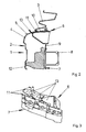
- FIG. 2 shows the front construction of the motor vehicle from FIG. 1 in a sectional view along the line II-II.
- the bumper 2 has an outer shell part 4 with an outer skin 5.
- the support 6 has a vertical mounting flange 9 for attachment to the body part 8 of the motor vehicle.
- the outer shell part 4 rests with a horizontal leg 10 on a cantilever 11 of the support 6, wherein the cantilever 11 is guided exclusively up to the central region of the horizontal leg 10 of the outer shell part 4.
- the free end of the horizontal leg 10 is locked with the cantilever 11.
- the damping element 7 is arranged between the outer shell part 4 and the body part 8 and supports a lower end of a vertical leg 12 of the outer shell part 4.
- the cantilever 11 forms the top of a held by the mounting flange 9 box-shaped projection 13 of the support. 6
- the shell part 4 In the area between the damping element 7, which supports the outer shell part 4 at the lower boundary and the support 6, which supports the outer shell part 4 vertically to the upper boundary, the shell part 4 has no support.
- This has the outer shell part 4 a deformation space in which it can deform during a load in and against the direction of travel.
- An impact of a pedestrian, especially in the lower leg of the bumper 2 sets the shell part 4 also only a small resistance, since the support 6 is guided only in the central region of the horizontal leg 10 of the outer shell part 4.
- the damping element 7 and the fastening flange 9 of the support 6 also deform.
- the fastening flange 9 of the support 6 can also be separated from the body part 8 in the event of a particularly pronounced impact.
- further deformation space is available.
- the support 6 has a high stability and is able to reliably support operating forces acting in the shell part 4.
- the bumper 2 is reliably held in its position and shape during operation of the motor vehicle.
- Figure 3 illustrates the arrangement of the support 6 and the damping element 7 below the outer shell part shown in Figure 2 in a perspective view. It can be seen here that the support 6 has a plurality of box-shaped projections 13, on each of which a cantilever beam is arranged.
- the damping element 7 is made of plastic foam and supports the outer shell part shown in Figure 2 at several points.
Landscapes
- Engineering & Computer Science (AREA)
- Mechanical Engineering (AREA)
- Body Structure For Vehicles (AREA)
Abstract
Description
- Die Erfindung betrifft einen Vorderbau für ein Kraftfahrzeug mit einem Karosserieteil des Kraftfahrzeuges, mit einem in Fahrtrichtung weisenden Stoßfänger und mit einer Stütze zur Abstützung eines äußeren Schalenteils des Stoßfängers an dem Karosserieteil.
- Ein solcher Vorderbau ist beispielsweise aus der
EP 1 193 135 A1 bekannt. Bei diesem Vorderbau weist die Stütze eine Reihe von nebeneinander angeordneten Federelementen auf, welche sich an dem äußeren Schalenteil abstützen. Die Federelemente stützen sich an einem Schalenkörper ab. Im Falle eines Aufpralls eines Fußgängers auf den Stoßfänger können die Federelemente begrenzt elastisch nachgeben. Nachteilig bei diesem Vorderbau ist jedoch, dass die Federelemente und der Schalenkörper nur einen sehr kleinen Deformationsweg ermöglichen und zudem das äußere Schalenteil eine weitere Versteifung des Stoßfängers in Fahrtrichtung erzeugt. Zudem überragt das äußere Schalenteil die Federelemente in vertikaler Richtung, so dass der Stoßfänger bei einer Belastung vertikal von oben weicher ist als in Fahrtrichtung. Daher vermag der Stoßfänger vertikal von oben eingeleitete Betriebskräfte nur unzureichend abzustützen. Bei einem Aufprall eines Fußgängers auf den bekannten Vorderbau, insbesondere mit seinem unteren Beinbereich, bietet der Stoßfänger einen hohen Widerstand, was zu einem hohen Verletzungsrisiko des Fußgängers führt. - Weiterhin ist aus der
DE 199 12 272 A1 ein Vorderbau für ein Kraftfahrzeug bekannt geworden, bei dem hinter dem äußeren Schalenteil des Stoßfängers eine Distanzkonsole angeordnet ist. Die Distanzkonsole ist mit Abstand zu dem äußeren Schalenteil angeordnet und hat eine Anschlagplatte, auf der das äußere Schalenteil bei einem Aufprall eines Fußgängers auf den Stoßfänger auftrifft. Die Distanzkonsole weist mehrere Abschnitte mit unterschiedlichen Steifigkeiten auf. Nachteilig ist auch bei diesem Vorderbau, dass vertikal von oben in den Stoßfänger eingeleitete Betriebskräfte nur unzureichend abgestützt werden. In Fahrtrichtung weist der Vorderbau jedoch sehr große Abmessungen auf. - Der Erfindung liegt das Problem zugrunde, einen Vorderbau der eingangs genannten Art so weiterzubilden, dass er vertikale Betriebskräfte zuverlässig abstützt und in Fahrtrichtung einen vorgesehenen Deformationsweg mit geringer Steifigkeit aufweist.
- Dieses Problem wird erfindungsgemäß dadurch gelöst, dass das äußere Schalenteil auf der Oberseite der Stütze aufliegt und dass eine in Fahrtrichtung weisende Wandung des äußeren Schalenteils von der Stütze beabstandet ist.
- Durch diese Gestaltung hat der Stoßfänger in Fahrtrichtung eine geringere Steifigkeit als in der vorgesehenen Montagelage vertikal von oben. Daher vermag der erfindungsgemäße Vorderbau vertikal von oben in den Stoßfänger eingeleitete Betriebskräfte zuverlässig abzustützen. Die Stabilität des Stoßfängers in Fahrtrichtung lässt sich dank der Erfindung unabhängig von der Stabilität der Stütze festlegen, weil die Stütze von der in Fahrtrichtung weisenden Wandung des äußeren Schalenteils beabstandet ist. Damit weist der Stoßfänger zwischen der in Fahrtrichtung weisenden Wandung des äußeren Schalenteils und der Stütze eine Verformungszone auf, in der sich das äußere Schalenteil bereits bei geringen Belastungen verformen kann. Erst wenn das äußere Schalenteil um die Verformungszone gestaucht wurde, wird die in Fahrtrichtung weisende Wandung des Schalenteils von der Stütze abgestützt.
- Die Bemessung des Verhältnisses der Steifigkeit des Stoßfängers in Fahrtrichtung und vertikal von oben gestaltet sich gemäß einer vorteilhaften Weiterbildung der Erfindung konstruktiv besonders einfach, wenn die Stütze einen Kragträger hat und wenn ein horizontaler oberer Schenkel des äußeren Schalenteils auf dem Kragträger aufliegt. Durch diese Gestaltung werden vertikal von oben in das äußere Schalenteil eingeleitete Kräfte unmittelbar von dem Kragträger abgestützt. Daher weist der Stoßfänger in dieser Richtung eine hohe Stabilität auf. In Fahrtrichtung des Kraftfahrzeuges unterbleibt die Unterstützung des äußeren Schalenteils durch die Stütze, so dass der Stoßfänger in dieser Richtung eine geringe Steifigkeit aufweist.
- Hohe Belastungen des äußeren Schalenteils bei einer vertikalen Belastung von oben lassen sich gemäß einer anderen vorteilhaften Weiterbildung der Erfindung einfach vermeiden, wenn der Kragträger bis über den mittleren Bereich des horizontalen Schenkels des äußeren Schalenteils geführt ist.
- Die Montage des erfindungsgemäßen Vorderbaus gestaltet sich besonders einfach, wenn der Kragträger mit dem äußeren Schalenteil verrastet ist.
- Zur weiteren Vereinfachung der Montage des erfindungsgemäßen Vorderbaus trägt es bei, wenn die Stütze einen vertikal nach oben weisenden Befestigungsflansch zur Verbindung mit dem Karosserieteil hat. Der Befestigungsflansch kann beispielsweise mit dem Karosserieteil verschraubt oder vernietet sein. Weiterhin kann durch eine entsprechende Festigkeit des Befestigungsflansches sichergestellt werden, dass bei einem starken Aufprall auf den Stoßfänger sich der Befestigungsflansch verformt oder bricht und damit weiterer Deformationsweg des Stoßfängers geschaffen wird.
- Zur weiteren Erhöhung der Stabilität des Stoßfängers in vertikaler Richtung trägt es bei, wenn der Kragträger die Oberseite eines mit dem Befestigungsflansch der Stütze verbundenen kastenförmigen Vorsprungs bildet.
- Die Abstützung des äußeren Schalenteils des Stoßfängers in vertikaler Richtung erfolgt gemäß einer anderen vorteilhaften Weiterbildung der Erfindung an mehreren Stellen, wenn die Stütze mehrere kastenförmige Vorsprünge aufweist.
- Eine Nachgiebigkeit des äußeren Schalenteils über die gesamte Höhe des Stoßfängers lässt sich gemäß einer anderen vorteilhaften Weiterbildung der Erfindung einfach gewährleisten, wenn die Stütze das äußere Schalenteil ausschließlich im vertikal oberen Bereich abstützt.
- Ein baulicher Aufwand für eine neben der Stütze angeordnete, zusätzliche Abstützung des äußeren Schalenteils erfordert gemäß einer anderen vorteilhaften Weiterbildung der Erfindung einen besonders geringen baulichen Aufwand, wenn zwischen dem Karosserieteil und dem äußeren Schalenteil ein Dämpfungselement angeordnet ist.
- Eine einfache Auslegung der Stabilität über die gesamte Höhe des Stoßfängers wird gemäß einer anderen vorteilhaften Weiterbildung der Erfindung einfach ermöglicht, wenn das Dämpfungselement im Wesentlichen unterhalb der Stütze angeordnet ist.
- Der erfindungsgemäße Vorderbau gestaltet sich besonders kostengünstig, wenn das Dämpfungselement aus Kunststoffschaum gefertigt ist.
- Die Abstützung des äußeren Schalenteils von der Stütze und dem Dämpfungselement ermöglicht gemäß einer anderen vorteilhaften Weiterbildung der Erfindung einen großen Deformationsweg, wenn das untere Ende eines vertikalen Schenkels des äußeren Schalenteils an dem Dämpfungselement anliegt.
- Die Erfindung lässt verschiedene Ausführungsformen zu. Zur weiteren Verdeutlichung ihres Grundprinzips ist eine davon in der Zeichnung dargestellt und wird nachfolgend beschrieben. Die Zeichnung zeigt in
- Fig. 1
- perspektivisch ein Kraftfahrzeug mit einem erfindungsgemäßen Vorderbau,
- Fig. 2
- eine Schnittdarstellung durch den Vorderbau aus Figur 1 entlang der Linie II - II,
- Fig. 3
- perspektivisch Bauteile des erfindungsgemäßen Vorderbaus unterhalb eines äußeren Schalenteils,
- Figur 1 zeigt ein Kraftfahrzeug mit einem in Fahrtrichtung weisenden Vorderbau 1 mit einem Stoßfänger 2. Der Stoßfänger 2 grenzt im mittleren Bereich an einen Kühlergrill 3.
- Figur 2 zeigt den Vorderbau des Kraftfahrzeuges aus Figur 1 in einer Schnittdarstellung entlang der Linie II - II. Der Stoßfänger 2 weist ein äußeres Schalenteil 4 mit einer Außenhaut 5 auf. Unterhalb des äußeren Schalenteils 4 sind eine Stütze 6 und ein Dämpfungselement 7 angeordnet. Weiterhin ist zu erkennen, dass sich die Stütze 6 und das Dämpfungselement 7 an einem als Querträger ausgebildeten Karosserieteil 8 abstützen. Oberhalb des äußeren Schalenteils 4 schließt sich der Kühlergrill 3 an.
- Die Stütze 6 hat einen vertikalen Befestigungsflansch 9 zur Befestigung an dem Karosserieteil 8 des Kraftfahrzeuges. Das äußere Schalenteil 4 liegt mit einem horizontalen Schenkel 10 auf einem Kragträger 11 der Stütze 6 auf, wobei der Kragträger 11 ausschließlich bis zu dem mittleren Bereich des horizontalen Schenkels 10 des äußeren Schalenteils 4 geführt ist. Das freie Ende des horizontalen Schenkels 10 ist mit dem Kragträger 11 verrastet. Das Dämpfungselement 7 ist zwischen dem äußeren Schalenteil 4 und dem Karosserieteil 8 angeordnet und stützt ein unteres Ende eines vertikalen Schenkels 12 des äußeren Schalenteils 4 ab. Der Kragträger 11 bildet die Oberseite eines von dem Befestigungsflansch 9 gehaltenen kastenförmigen Vorsprungs 13 der Stütze 6.
- Im Bereich zwischen dem Dämpfungselement 7, welches das äußere Schalenteil 4 an der unteren Begrenzung abstützt und der Stütze 6, welche das äußere Schalenteil 4 vertikal an der oberen Begrenzung abstützt, hat das Schalenteil 4 keine Unterstützung. Damit hat das äußere Schalenteil 4 einen Deformationsraum, in dem es sich bei einer Belastung in und gegen die Fahrtrichtung verformen kann. Einem Aufprall eines Fußgängers, insbesondere im unteren Beinbereich auf den Stoßfänger 2 setzt das Schalenteil 4 zudem nur einen geringen Widerstand entgegen, da die Stütze 6 nur bis in den mittleren Bereich des horizontalen Schenkels 10 des äußeren Schalenteils 4 geführt ist. Bei einem starken Aufprall verformt sich zudem das Dämpfungselement 7 und der Befestigungsflansch 9 der Stütze 6. Der Befestigungsflansch 9 der Stütze 6 kann bei einem besonders starken Aufprall zudem von dem Karosserieteil 8 getrennt werden. Damit steht weiterer Deformationsraum zur Verfügung. In vertikaler Richtung von oben weist die Stütze 6 jedoch eine hohe Stabilität auf und vermag in das Schalenteil 4 einwirkende Betriebskräfte zuverlässig abzustützen. Damit wird der Stoßfänger 2 während des Betriebes des Kraftfahrzeuges zuverlässig in seiner Lage und Form gehalten.
- Figur 3 verdeutlicht die Anordnung der Stütze 6 und des Dämpfungselementes 7 unterhalb des in Figur 2 dargestellten äußeren Schalenteils in einer perspektivischen Ansicht. Hierbei ist zu erkennen, dass die Stütze 6 mehrere kastenförmige Vorsprünge 13, auf denen jeweils ein Kragträger angeordnet ist, aufweist. Das Dämpfungselement 7 ist aus Kunststoffschaum gefertigt und stützt das in Figur 2 dargestellte äußere Schalenteil an mehreren Stellen ab.
Claims (12)
- Vorderbau für ein Kraftfahrzeug mit einem Karosserieteil (8) des Kraftfahrzeuges, mit einem in Fahrtrichtung weisenden Stoßfänger (2) und mit einer Stütze (6) zur Abstützung eines äußeren Schalenteils (4) des Stoßfängers (2) an dem Karosserieteil (8), dadurch gekennzeichnet, dass das äußere Schalenteil (4) auf der Oberseite der Stütze (6) aufliegt und dass eine in Fahrtrichtung weisenden Wandung des äußeren Schalenteils (4) von der Stütze (6) beabstandet ist.
- Vorderbau nach Anspruch 1, dadurch gekennzeichnet, dass die Stütze (6) einen Kragträger (11) hat und dass ein horizontaler oberer Schenkel (10) des äußeren Schalenteils (4) auf dem Kragträger (11) aufliegt.
- Vorderbau nach Anspruch 1 oder 2, dadurch gekennzeichnet, dass der Kragträger (11) bis über den mittleren Bereich des horizontalen Schenkels (10) des äußeren Schalenteils (4) geführt ist.
- Vorderbau nach zumindest einem der vorhergehenden Ansprüche, dadurch gekennzeichnet, dass der Kragträger (11) mit dem äußeren Schalenteil (4) verrastet ist.
- Vorderbau nach zumindest einem der vorhergehenden Ansprüche, dadurch gekennzeichnet, dass die Stütze (6) einen vertikal nach oben weisenden Befestigungsflansch (9) zur Verbindung mit dem Karosserieteil (8) hat.
- Vorderbau nach zumindest einem der vorhergehenden Ansprüche, dadurch gekennzeichnet, dass der Kragträger (11) die Oberseite eines mit dem Befestigungsflansch (9) der Stütze (6) verbundenen kastenförmigen Vorsprungs (13) bildet.
- Vorderbau nach zumindest einem der vorhergehenden Ansprüche, dadurch gekennzeichnet, dass die Stütze (6) mehrere kastenförmige Vorsprünge (13) aufweist.
- Vorderbau nach zumindest einem der vorhergehenden Ansprüche, dadurch gekennzeichnet, dass die Stütze (6) das äußere Schalenteil (4) ausschließlich im vertikal oberen Bereich abstützt.
- Vorderbau nach zumindest einem der vorhergehenden Ansprüche, dadurch gekennzeichnet, dass zwischen dem Karosserieteil (8) und dem äußeren Schalenteil (4) ein Dämpfungselement (7) angeordnet ist.
- Vorderbau nach zumindest einem der vorhergehenden Ansprüche, dadurch gekennzeichnet, dass das Dämpfungselement (7) im Wesentlichen unterhalb der Stütze (6) angeordnet ist.
- Vorderbau nach zumindest einem der vorhergehenden Ansprüche, dadurch gekennzeichnet, dass das Dämpfungselement (7) aus Kunststoffschaum gefertigt ist.
- Vorderbau nach zumindest einem der vorhergehenden Ansprüche, dadurch gekennzeichnet, dass das untere Ende eines vertikalen Schenkels (12) des äußeren Schalenteils (4) an dem Dämpfungselement (7) anliegt.
Applications Claiming Priority (1)
| Application Number | Priority Date | Filing Date | Title |
|---|---|---|---|
| DE102005027178A DE102005027178A1 (de) | 2005-06-13 | 2005-06-13 | Vorderbau für ein Kraftfahrzeug |
Publications (3)
| Publication Number | Publication Date |
|---|---|
| EP1733926A2 true EP1733926A2 (de) | 2006-12-20 |
| EP1733926A3 EP1733926A3 (de) | 2009-11-18 |
| EP1733926B1 EP1733926B1 (de) | 2017-03-22 |
Family
ID=36649507
Family Applications (1)
| Application Number | Title | Priority Date | Filing Date |
|---|---|---|---|
| EP06011454.3A Not-in-force EP1733926B1 (de) | 2005-06-13 | 2006-06-02 | Vorderbau für ein Kraftfahrzeug |
Country Status (2)
| Country | Link |
|---|---|
| EP (1) | EP1733926B1 (de) |
| DE (1) | DE102005027178A1 (de) |
Cited By (1)
| Publication number | Priority date | Publication date | Assignee | Title |
|---|---|---|---|---|
| DE102010050377A1 (de) * | 2010-11-03 | 2012-05-03 | Volkswagen Ag | Front- oder Heckend an einem Fahrzeug |
Families Citing this family (6)
| Publication number | Priority date | Publication date | Assignee | Title |
|---|---|---|---|---|
| DE102007025726A1 (de) * | 2007-06-01 | 2008-12-04 | Audi Ag | Stoßfänger für ein Kraftfahrzeug |
| JP5440207B2 (ja) * | 2010-01-22 | 2014-03-12 | スズキ株式会社 | 車体前部構造 |
| DE102012008832A1 (de) * | 2012-04-28 | 2013-10-31 | Volkswagen Aktiengesellschaft | Vorbaustruktur eines Kraftfahrzeugs |
| DE102012022956A1 (de) | 2012-11-23 | 2013-08-01 | Daimler Ag | Stoßfängeranordnung für einen Personenkraftwagen |
| US9580029B2 (en) * | 2015-06-05 | 2017-02-28 | Toyota Motor Engineering & Manufacturing North America, Inc. | Bumper assemblies including a bumper cover reinforcement and vehicles incorporating the same |
| DE102019114300B4 (de) * | 2019-05-28 | 2024-06-27 | Bayerische Motoren Werke Aktiengesellschaft | Abstützelement für eine Karosserieverkleidung eines Fahrzeugs und Fahrzeug |
Citations (2)
| Publication number | Priority date | Publication date | Assignee | Title |
|---|---|---|---|---|
| DE19912272A1 (de) | 1999-03-18 | 2000-09-28 | Benteler Werke Ag | Stoßfängeranordnung |
| EP1193135A1 (de) | 2000-10-02 | 2002-04-03 | Benteler Automobiltechnik GmbH & Co. KG | Stossfängeranordnung |
Family Cites Families (10)
| Publication number | Priority date | Publication date | Assignee | Title |
|---|---|---|---|---|
| JPS62120052U (de) * | 1986-01-23 | 1987-07-30 | ||
| US4950031A (en) * | 1987-07-04 | 1990-08-21 | Mazda Motor Corporation | Automobile rear underbody structure |
| US5431464A (en) * | 1993-12-07 | 1995-07-11 | General Motors Corporation | Collapsible fascia support for an automotive bumper |
| DE4432766A1 (de) * | 1994-09-14 | 1996-07-04 | Braun Pebra Gmbh | Stoßfänger für die Frontpartie eines Straßenfahrzeuges |
| DE19805384C2 (de) * | 1998-02-11 | 2001-07-12 | Daimler Chrysler Ag | Anordnung zur Befestigung eines Stoßfängers an einer Fahrzeugkarosserie |
| DE10156893B4 (de) * | 2001-11-20 | 2008-10-02 | Daimler Ag | Kraftfahrzeug mit einem Stoßfänger |
| DE10156892A1 (de) * | 2001-11-20 | 2003-05-28 | Daimler Chrysler Ag | Kraftfahrzeug-Stoßfänger und Kraftfahrzeug |
| FR2833054B1 (fr) * | 2001-12-05 | 2004-07-02 | Peugeot Citroen Automobiles Sa | Dispositif d'absorption d'energie cinetique a resistance elastique et a flambage, et application |
| DE10237454B3 (de) * | 2002-08-13 | 2004-02-05 | Decoma (Germany) Gmbh | Frontend-Modul für ein Kraftfahrzeug |
| DE10312510B3 (de) * | 2003-03-20 | 2005-01-20 | Daimlerchrysler Ag | Stoßfänger für einen Kraftwagen |
-
2005
- 2005-06-13 DE DE102005027178A patent/DE102005027178A1/de not_active Withdrawn
-
2006
- 2006-06-02 EP EP06011454.3A patent/EP1733926B1/de not_active Not-in-force
Patent Citations (2)
| Publication number | Priority date | Publication date | Assignee | Title |
|---|---|---|---|---|
| DE19912272A1 (de) | 1999-03-18 | 2000-09-28 | Benteler Werke Ag | Stoßfängeranordnung |
| EP1193135A1 (de) | 2000-10-02 | 2002-04-03 | Benteler Automobiltechnik GmbH & Co. KG | Stossfängeranordnung |
Cited By (2)
| Publication number | Priority date | Publication date | Assignee | Title |
|---|---|---|---|---|
| DE102010050377A1 (de) * | 2010-11-03 | 2012-05-03 | Volkswagen Ag | Front- oder Heckend an einem Fahrzeug |
| DE102010050377B4 (de) * | 2010-11-03 | 2024-09-26 | Volkswagen Ag | Front- oder Heckend an einem Fahrzeug |
Also Published As
| Publication number | Publication date |
|---|---|
| DE102005027178A1 (de) | 2006-12-14 |
| EP1733926B1 (de) | 2017-03-22 |
| EP1733926A3 (de) | 2009-11-18 |
Similar Documents
| Publication | Publication Date | Title |
|---|---|---|
| DE102017118515B3 (de) | Fahrzeuglängsträgeranordnung | |
| DE102012213867B4 (de) | Fahrzeugkarosseriefrontstruktur | |
| WO2019072653A1 (de) | Stossfängerquerträger | |
| DE102005059447A1 (de) | Stoßfängersystem für ein Kraftfahrzeug | |
| DE102020214064A1 (de) | Fahrzeugfrontstruktur | |
| DE102012111643A1 (de) | Abstütz-Struktur von Tür-Aufprallbalken für Fahrzeug | |
| DE102009041771A1 (de) | Hilfsrahmen für ein Kraftfahrzeug | |
| DE102014203990A1 (de) | Fussgänger-freundliche Konstruktion für ein Frontende eines Kraftfahrzeugs | |
| DE102009012057A1 (de) | Vorrichtung zum Aufnehmen von Seitenkräften | |
| DE102015007453A1 (de) | Kraftfahrzeugkarosserie | |
| EP2643181B1 (de) | Frontendmodul-anordnung für eine karosserie eines personenkraftwagens | |
| DE102010023281A1 (de) | Karosseriestruktur mit einem Scheibenquerträger für ein Kraftfahrzeug mit einer Windschutzscheibe | |
| DE102008013832B4 (de) | Energie absorbierendes Verbindungselement | |
| DE102004007571B4 (de) | Vorderwagen für ein Fahrzeug, insbesondere für ein Kraftfahrzeug | |
| EP1733926B1 (de) | Vorderbau für ein Kraftfahrzeug | |
| DE102012023946A1 (de) | Querträger, insbesondere Stirnwandquerträger für ein Kraftfahrzeug und korrespondierende Stirnwandstruktur | |
| EP1641658A1 (de) | Fronthaubensystem | |
| DE102004027169B4 (de) | Kraftfahrzeugfront mit Mitten-Abdeckung im Spoilerbereich zum verbesserten Kollisionsschutz von Fußgängern | |
| EP2996908B1 (de) | Fahrzeug mit einem knickelement zwischen der grundkarosserie und einem aussenkarosserieteil | |
| EP0858943B1 (de) | Kraftfahrzeug mit einer Abstützung zwischen Querträger und Spritzschutzwand | |
| DE102009039805A1 (de) | Vorderbau zur Verbindung mit einer Karosserie eines Kraftfahrzeuges | |
| DE102018208194A1 (de) | Befestigungselement zur Befestigung eines Scheinwerfers an einem Längsträger in einem Vorderwagen eines Kraftfahrzeuges sowie Anordnung eines Befestigungselements in einem Vorderwagen eines Kraftfahrzeuges | |
| DE102013100585B4 (de) | Aufbaustruktur und Kraftfahrzeug | |
| DE102020117209A1 (de) | Verfahren zum Fertigen einer Karosserie für einen Kraftwagen und Karosserie für einen Kraftwagen | |
| DE102016013877A1 (de) | Stützanordnung für einen Stoßfänger eines Kraftwagens |
Legal Events
| Date | Code | Title | Description |
|---|---|---|---|
| PUAI | Public reference made under article 153(3) epc to a published international application that has entered the european phase |
Free format text: ORIGINAL CODE: 0009012 |
|
| AK | Designated contracting states |
Kind code of ref document: A2 Designated state(s): AT BE BG CH CY CZ DE DK EE ES FI FR GB GR HU IE IS IT LI LT LU LV MC NL PL PT RO SE SI SK TR |
|
| AX | Request for extension of the european patent |
Extension state: AL BA HR MK YU |
|
| PUAL | Search report despatched |
Free format text: ORIGINAL CODE: 0009013 |
|
| AK | Designated contracting states |
Kind code of ref document: A3 Designated state(s): AT BE BG CH CY CZ DE DK EE ES FI FR GB GR HU IE IS IT LI LT LU LV MC NL PL PT RO SE SI SK TR |
|
| AX | Request for extension of the european patent |
Extension state: AL BA HR MK YU |
|
| 17P | Request for examination filed |
Effective date: 20100518 |
|
| 17Q | First examination report despatched |
Effective date: 20100610 |
|
| AKX | Designation fees paid |
Designated state(s): AT BE BG CH CY CZ DE DK EE ES FI FR GB GR HU IE IS IT LI LT LU LV MC NL PL PT RO SE SI SK TR |
|
| RAP1 | Party data changed (applicant data changed or rights of an application transferred) |
Owner name: GM GLOBAL TECHNOLOGY OPERATIONS LLC |
|
| GRAP | Despatch of communication of intention to grant a patent |
Free format text: ORIGINAL CODE: EPIDOSNIGR1 |
|
| INTG | Intention to grant announced |
Effective date: 20160826 |
|
| GRAS | Grant fee paid |
Free format text: ORIGINAL CODE: EPIDOSNIGR3 |
|
| GRAJ | Information related to disapproval of communication of intention to grant by the applicant or resumption of examination proceedings by the epo deleted |
Free format text: ORIGINAL CODE: EPIDOSDIGR1 |
|
| GRAL | Information related to payment of fee for publishing/printing deleted |
Free format text: ORIGINAL CODE: EPIDOSDIGR3 |
|
| GRAP | Despatch of communication of intention to grant a patent |
Free format text: ORIGINAL CODE: EPIDOSNIGR1 |
|
| GRAA | (expected) grant |
Free format text: ORIGINAL CODE: 0009210 |
|
| INTG | Intention to grant announced |
Effective date: 20170207 |
|
| AK | Designated contracting states |
Kind code of ref document: B1 Designated state(s): AT BE BG CH CY CZ DE DK EE ES FI FR GB GR HU IE IS IT LI LT LU LV MC NL PL PT RO SE SI SK TR |
|
| REG | Reference to a national code |
Ref country code: GB Ref legal event code: FG4D Free format text: NOT ENGLISH |
|
| REG | Reference to a national code |
Ref country code: CH Ref legal event code: EP |
|
| REG | Reference to a national code |
Ref country code: AT Ref legal event code: REF Ref document number: 877388 Country of ref document: AT Kind code of ref document: T Effective date: 20170415 |
|
| REG | Reference to a national code |
Ref country code: IE Ref legal event code: FG4D Free format text: LANGUAGE OF EP DOCUMENT: GERMAN |
|
| REG | Reference to a national code |
Ref country code: DE Ref legal event code: R096 Ref document number: 502006015424 Country of ref document: DE |
|
| REG | Reference to a national code |
Ref country code: NL Ref legal event code: MP Effective date: 20170322 |
|
| PG25 | Lapsed in a contracting state [announced via postgrant information from national office to epo] |
Ref country code: GR Free format text: LAPSE BECAUSE OF FAILURE TO SUBMIT A TRANSLATION OF THE DESCRIPTION OR TO PAY THE FEE WITHIN THE PRESCRIBED TIME-LIMIT Effective date: 20170623 Ref country code: LT Free format text: LAPSE BECAUSE OF FAILURE TO SUBMIT A TRANSLATION OF THE DESCRIPTION OR TO PAY THE FEE WITHIN THE PRESCRIBED TIME-LIMIT Effective date: 20170322 Ref country code: FI Free format text: LAPSE BECAUSE OF FAILURE TO SUBMIT A TRANSLATION OF THE DESCRIPTION OR TO PAY THE FEE WITHIN THE PRESCRIBED TIME-LIMIT Effective date: 20170322 |
|
| PGFP | Annual fee paid to national office [announced via postgrant information from national office to epo] |
Ref country code: DE Payment date: 20170530 Year of fee payment: 12 |
|
| REG | Reference to a national code |
Ref country code: LT Ref legal event code: MG4D |
|
| PG25 | Lapsed in a contracting state [announced via postgrant information from national office to epo] |
Ref country code: LV Free format text: LAPSE BECAUSE OF FAILURE TO SUBMIT A TRANSLATION OF THE DESCRIPTION OR TO PAY THE FEE WITHIN THE PRESCRIBED TIME-LIMIT Effective date: 20170322 Ref country code: BG Free format text: LAPSE BECAUSE OF FAILURE TO SUBMIT A TRANSLATION OF THE DESCRIPTION OR TO PAY THE FEE WITHIN THE PRESCRIBED TIME-LIMIT Effective date: 20170622 Ref country code: SE Free format text: LAPSE BECAUSE OF FAILURE TO SUBMIT A TRANSLATION OF THE DESCRIPTION OR TO PAY THE FEE WITHIN THE PRESCRIBED TIME-LIMIT Effective date: 20170322 |
|
| PG25 | Lapsed in a contracting state [announced via postgrant information from national office to epo] |
Ref country code: NL Free format text: LAPSE BECAUSE OF FAILURE TO SUBMIT A TRANSLATION OF THE DESCRIPTION OR TO PAY THE FEE WITHIN THE PRESCRIBED TIME-LIMIT Effective date: 20170322 |
|
| PG25 | Lapsed in a contracting state [announced via postgrant information from national office to epo] |
Ref country code: IT Free format text: LAPSE BECAUSE OF FAILURE TO SUBMIT A TRANSLATION OF THE DESCRIPTION OR TO PAY THE FEE WITHIN THE PRESCRIBED TIME-LIMIT Effective date: 20170322 Ref country code: ES Free format text: LAPSE BECAUSE OF FAILURE TO SUBMIT A TRANSLATION OF THE DESCRIPTION OR TO PAY THE FEE WITHIN THE PRESCRIBED TIME-LIMIT Effective date: 20170322 Ref country code: CZ Free format text: LAPSE BECAUSE OF FAILURE TO SUBMIT A TRANSLATION OF THE DESCRIPTION OR TO PAY THE FEE WITHIN THE PRESCRIBED TIME-LIMIT Effective date: 20170322 Ref country code: SK Free format text: LAPSE BECAUSE OF FAILURE TO SUBMIT A TRANSLATION OF THE DESCRIPTION OR TO PAY THE FEE WITHIN THE PRESCRIBED TIME-LIMIT Effective date: 20170322 Ref country code: EE Free format text: LAPSE BECAUSE OF FAILURE TO SUBMIT A TRANSLATION OF THE DESCRIPTION OR TO PAY THE FEE WITHIN THE PRESCRIBED TIME-LIMIT Effective date: 20170322 Ref country code: RO Free format text: LAPSE BECAUSE OF FAILURE TO SUBMIT A TRANSLATION OF THE DESCRIPTION OR TO PAY THE FEE WITHIN THE PRESCRIBED TIME-LIMIT Effective date: 20170322 |
|
| PG25 | Lapsed in a contracting state [announced via postgrant information from national office to epo] |
Ref country code: PL Free format text: LAPSE BECAUSE OF FAILURE TO SUBMIT A TRANSLATION OF THE DESCRIPTION OR TO PAY THE FEE WITHIN THE PRESCRIBED TIME-LIMIT Effective date: 20170322 Ref country code: IS Free format text: LAPSE BECAUSE OF FAILURE TO SUBMIT A TRANSLATION OF THE DESCRIPTION OR TO PAY THE FEE WITHIN THE PRESCRIBED TIME-LIMIT Effective date: 20170722 Ref country code: PT Free format text: LAPSE BECAUSE OF FAILURE TO SUBMIT A TRANSLATION OF THE DESCRIPTION OR TO PAY THE FEE WITHIN THE PRESCRIBED TIME-LIMIT Effective date: 20170724 |
|
| REG | Reference to a national code |
Ref country code: DE Ref legal event code: R097 Ref document number: 502006015424 Country of ref document: DE |
|
| PLBE | No opposition filed within time limit |
Free format text: ORIGINAL CODE: 0009261 |
|
| STAA | Information on the status of an ep patent application or granted ep patent |
Free format text: STATUS: NO OPPOSITION FILED WITHIN TIME LIMIT |
|
| PG25 | Lapsed in a contracting state [announced via postgrant information from national office to epo] |
Ref country code: MC Free format text: LAPSE BECAUSE OF FAILURE TO SUBMIT A TRANSLATION OF THE DESCRIPTION OR TO PAY THE FEE WITHIN THE PRESCRIBED TIME-LIMIT Effective date: 20170322 Ref country code: DK Free format text: LAPSE BECAUSE OF FAILURE TO SUBMIT A TRANSLATION OF THE DESCRIPTION OR TO PAY THE FEE WITHIN THE PRESCRIBED TIME-LIMIT Effective date: 20170322 |
|
| REG | Reference to a national code |
Ref country code: CH Ref legal event code: PL |
|
| 26N | No opposition filed |
Effective date: 20180102 |
|
| GBPC | Gb: european patent ceased through non-payment of renewal fee |
Effective date: 20170622 |
|
| PG25 | Lapsed in a contracting state [announced via postgrant information from national office to epo] |
Ref country code: SI Free format text: LAPSE BECAUSE OF FAILURE TO SUBMIT A TRANSLATION OF THE DESCRIPTION OR TO PAY THE FEE WITHIN THE PRESCRIBED TIME-LIMIT Effective date: 20170322 |
|
| REG | Reference to a national code |
Ref country code: IE Ref legal event code: MM4A |
|
| REG | Reference to a national code |
Ref country code: FR Ref legal event code: ST Effective date: 20180228 |
|
| PG25 | Lapsed in a contracting state [announced via postgrant information from national office to epo] |
Ref country code: LI Free format text: LAPSE BECAUSE OF NON-PAYMENT OF DUE FEES Effective date: 20170630 Ref country code: GB Free format text: LAPSE BECAUSE OF NON-PAYMENT OF DUE FEES Effective date: 20170622 Ref country code: IE Free format text: LAPSE BECAUSE OF NON-PAYMENT OF DUE FEES Effective date: 20170602 Ref country code: CH Free format text: LAPSE BECAUSE OF NON-PAYMENT OF DUE FEES Effective date: 20170630 Ref country code: LU Free format text: LAPSE BECAUSE OF NON-PAYMENT OF DUE FEES Effective date: 20170602 |
|
| PG25 | Lapsed in a contracting state [announced via postgrant information from national office to epo] |
Ref country code: FR Free format text: LAPSE BECAUSE OF NON-PAYMENT OF DUE FEES Effective date: 20170630 |
|
| REG | Reference to a national code |
Ref country code: BE Ref legal event code: MM Effective date: 20170630 |
|
| REG | Reference to a national code |
Ref country code: AT Ref legal event code: MM01 Ref document number: 877388 Country of ref document: AT Kind code of ref document: T Effective date: 20170602 |
|
| PG25 | Lapsed in a contracting state [announced via postgrant information from national office to epo] |
Ref country code: BE Free format text: LAPSE BECAUSE OF NON-PAYMENT OF DUE FEES Effective date: 20170630 |
|
| PG25 | Lapsed in a contracting state [announced via postgrant information from national office to epo] |
Ref country code: AT Free format text: LAPSE BECAUSE OF NON-PAYMENT OF DUE FEES Effective date: 20170602 |
|
| REG | Reference to a national code |
Ref country code: DE Ref legal event code: R119 Ref document number: 502006015424 Country of ref document: DE |
|
| PG25 | Lapsed in a contracting state [announced via postgrant information from national office to epo] |
Ref country code: DE Free format text: LAPSE BECAUSE OF NON-PAYMENT OF DUE FEES Effective date: 20190101 |
|
| PG25 | Lapsed in a contracting state [announced via postgrant information from national office to epo] |
Ref country code: HU Free format text: LAPSE BECAUSE OF FAILURE TO SUBMIT A TRANSLATION OF THE DESCRIPTION OR TO PAY THE FEE WITHIN THE PRESCRIBED TIME-LIMIT; INVALID AB INITIO Effective date: 20060602 |
|
| PG25 | Lapsed in a contracting state [announced via postgrant information from national office to epo] |
Ref country code: CY Free format text: LAPSE BECAUSE OF NON-PAYMENT OF DUE FEES Effective date: 20170322 |
|
| PG25 | Lapsed in a contracting state [announced via postgrant information from national office to epo] |
Ref country code: TR Free format text: LAPSE BECAUSE OF FAILURE TO SUBMIT A TRANSLATION OF THE DESCRIPTION OR TO PAY THE FEE WITHIN THE PRESCRIBED TIME-LIMIT Effective date: 20170322 |