EP2996908B1 - Fahrzeug mit einem knickelement zwischen der grundkarosserie und einem aussenkarosserieteil - Google Patents
Fahrzeug mit einem knickelement zwischen der grundkarosserie und einem aussenkarosserieteil Download PDFInfo
- Publication number
- EP2996908B1 EP2996908B1 EP14719799.0A EP14719799A EP2996908B1 EP 2996908 B1 EP2996908 B1 EP 2996908B1 EP 14719799 A EP14719799 A EP 14719799A EP 2996908 B1 EP2996908 B1 EP 2996908B1
- Authority
- EP
- European Patent Office
- Prior art keywords
- vehicle
- bending
- cross member
- front apron
- buckling
- Prior art date
- Legal status (The legal status is an assumption and is not a legal conclusion. Google has not performed a legal analysis and makes no representation as to the accuracy of the status listed.)
- Active
Links
Images

Classifications
-
- B—PERFORMING OPERATIONS; TRANSPORTING
- B60—VEHICLES IN GENERAL
- B60R—VEHICLES, VEHICLE FITTINGS, OR VEHICLE PARTS, NOT OTHERWISE PROVIDED FOR
- B60R21/00—Arrangements or fittings on vehicles for protecting or preventing injuries to occupants or pedestrians in case of accidents or other traffic risks
- B60R21/34—Protecting non-occupants of a vehicle, e.g. pedestrians
-
- B—PERFORMING OPERATIONS; TRANSPORTING
- B60—VEHICLES IN GENERAL
- B60R—VEHICLES, VEHICLE FITTINGS, OR VEHICLE PARTS, NOT OTHERWISE PROVIDED FOR
- B60R19/00—Wheel guards; Radiator guards, e.g. grilles; Obstruction removers; Fittings damping bouncing force in collisions
- B60R19/52—Radiator or grille guards ; Radiator grilles
-
- B—PERFORMING OPERATIONS; TRANSPORTING
- B62—LAND VEHICLES FOR TRAVELLING OTHERWISE THAN ON RAILS
- B62D—MOTOR VEHICLES; TRAILERS
- B62D21/00—Understructures, i.e. chassis frame on which a vehicle body may be mounted
- B62D21/15—Understructures, i.e. chassis frame on which a vehicle body may be mounted having impact absorbing means, e.g. a frame designed to permanently or temporarily change shape or dimension upon impact with another body
- B62D21/152—Front or rear frames
-
- B—PERFORMING OPERATIONS; TRANSPORTING
- B60—VEHICLES IN GENERAL
- B60R—VEHICLES, VEHICLE FITTINGS, OR VEHICLE PARTS, NOT OTHERWISE PROVIDED FOR
- B60R21/00—Arrangements or fittings on vehicles for protecting or preventing injuries to occupants or pedestrians in case of accidents or other traffic risks
- B60R21/34—Protecting non-occupants of a vehicle, e.g. pedestrians
- B60R2021/343—Protecting non-occupants of a vehicle, e.g. pedestrians using deformable body panel, bodywork or components
Definitions
- the invention relates to a vehicle, in particular a passenger car or a truck, with a base body for supporting at least one outer body part.
- Body of today's passenger cars and trucks are usually designed in sections with a basic body and attached outer body panels.
- the basic body forms a kind of inner support frame, on which are then externally attached those body parts that form part or all of the outer skin of the body.
- a radiator cover and a bumper cover are provided on the front in the direction of travel, which are fastened on the inside to a front cross member or a front wall.
- the bumper cover forms the lower part of the assembly, while the radiator cover is disposed above and is bolted at its upper end to the cross member.
- the front of the vehicle must be made comparatively soft. For this purpose, comparatively complex precautions are currently being made on the basic body.
- a vehicle is provided with the features of claim 1.
- a buckling element according to the invention, the flexibility required on outer body parts is intentionally placed in an interface or a region between outer body part and basic body. In this area, a targeted flexible buckling element is provided, which kinks in an impact and thus absorbs energy.
- the cross-section of the creasing element is designed for this purpose at predetermined sections with adapted area moments of inertia. Furthermore, the Auflagerung and the clamping of the Knickelements are adjusted accordingly.
- Kinking is understood to mean the loss of the stability of the kink element up to the sudden and violent failure.
- the buckling element is for this purpose preferably designed with at least one straight or slightly curved rod or beam. This buckling element is placed so that the impact energy is introduced into the buckling element under the action of compressive forces whose line of action lies in the rod axis, and / or under the action of bending moments.
- the loss of stability manifests itself in the load rapidly growing changes in shape of the Knickelements above a certain load (buckling load), with a lateral deflection of the bar axis or beam axis (bending buckling) or a twisting of the bar or beam cross-section (twisting) or a lateral deflection of the bar axis or beam axis and a twisting of the bar or beam cross-section (bending torsional buckling, previously also referred to as tilting).
- the buckling element according to the invention is designed with an elongated bending edge. This results in a flat buckling element, which is selectively deformed during an impact along the bending edge. It can be transmitted as impact energy in zones of the body, which are located away from the point of impact.
- the bending edge is preferably aligned transversely to the longitudinal axis of the vehicle. Such a bending edge is in particular in front of a frontal impact before especially in a pedestrian impact from the front, an advantage.
- the buckling edge also extends over the entire widthwise extent of the outer body part. Such bending edges provide their buckling effect over a wide or large area of the outer body.
- the outer body part comprises a radiator cover.
- a radiator cover can also advantageously at the same time a bumper fascia be kept in particular in one piece.
- the buckling element according to the invention is arranged between the upper edge region of the radiator cover and a front cross member of the base body.
- the kink element develops its effect at the upper edge of the radiator cowling and is particularly helpful in case of a pedestrian impact. Furthermore, the buckling element under the local hood has sufficient space for its kink deflection.
- the buckling element according to the invention is formed integrally with the outer body part.
- the number of parts can be reduced and it can be used for the buckling advantageous manufacturing methods such as plastic injection or sheet metal presses, as they are also used for the outer body panels and / or the basic body.
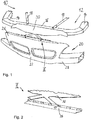
- a vehicle 10 illustrated with its base body 12 which is particularly formed with two aligned in the vehicle longitudinal direction or main direction, substantially parallel longitudinal members 14 and a connecting these, front cross member 16.
- the cross member 16 is additionally stiffened to the longitudinal members 14 with obliquely oriented corner struts 18, so that a largely torsionally rigid base body 12 is formed with the components 14, 16 and 18.
- a plurality of outer body panels 20 are externally mounted, of which in this case in particular a front apron 22 is shown.
- the front apron 22 extends substantially in the vertical direction over the entire front of the vehicle 10 below a bonnet 24.
- the front apron 22 is formed in its upper part by a radiator cowl 26 and in its lower part by a bumper fascia 28.
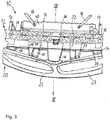
- a buckling element 32 is arranged.
- the buckling element 32 as a whole is integrally formed with the front apron 22 and therefore also integrally with the bumper cover 28 in a cost-saving manner in a manufacturing process.
- This buckling element 32 is arranged as a substantially flat plate with a trained therein, transverse to the direction of travel, arranged approximately centrally Knickkante 34 designed.
- the bending edge 34 is formed over the entire width extent of the Knickelements 32 and the radiator cowl 26 as an outer body part 20.
- the buckling element 32 is at least one support element 36 on the cross member 16, which in the present case designed in one piece with the buckling element 32 and is screwed to the cross member 16.
- the cross member 16 is in turn held with at least one holding element 38 on the two longitudinal members 14, in particular screwed, which are further connected to a second cross member 40.
- the two base braces 12, which stabilize the base body 12 are screwed on. So designed, occurring with the bending edge 34 in an impact energy impact can also be transferred to zones of the base body 12, which are remote from a point of impact on the vehicle 10.
- the buckling element 32 at the bending edge 34 alternately sections from above a bead 42 and from below a bead 44 as a groove-shaped depression on which particularly clearly in 4 and 5 are recognizable. Furthermore, in the substantially flat plate of the creasing element 32 with a ground plane 46 at least one compared to the base plane 46 in the vertical direction elevated, area or portion 48 is formed. With the at least one raised, flat portion 48, the buckling element 32 is adjusted as needed in its area moments of inertia. In the present embodiment, nine such sections 48 are formed, which are arranged offset at the bending edge 34. Alternatively, in other variants of the solution according to the invention not shown, a different arrangement of the sections 48 is possible as required.
- the buckling element 32 can bend in the case of an external, front-acting force 50, as occurs in an impact, predetermined, in the present case selectively bend at the bending edge 34 upwards.
- a maximum possible kink deflection is in particular by means of the beads 42 and 44 with their width and depth extensions and by means of the at least one portion 48th determined with its width and height extension.
- Such a maximum possible buckling deflection is further defined so that the hood 24 is not touched by the buckling element 32 at maximum deflection. For this purpose, a corresponding clearance is created at a distance 52 between the buckling element 32 and the bonnet 24.
- the front apron 22 is initially displaced in the direction of the vehicle interior due to the force 50, as a result of which the buckling element 32 is bent upward at the bent edge 34.
- an impact energy occurring upon impact is absorbed by conversion into deformation energy and heat without causing damage to the vehicle 10.
- the cross member 16 remains at least virtually unchanged in its shape, which is made possible by means of the support element 36 and thus achieved a correspondingly adapted Auflagerung the Knickelements 32 on the cross member 16 ( Fig. 5 ).
- the impact energy of the vehicle 10 impacting on an object or a person is significantly reduced by means of the biting element 32 according to the invention.
Landscapes
- Engineering & Computer Science (AREA)
- Mechanical Engineering (AREA)
- Chemical & Material Sciences (AREA)
- Combustion & Propulsion (AREA)
- Transportation (AREA)
- Body Structure For Vehicles (AREA)
Description
- Die Erfindung betrifft ein Fahrzeug, insbesondere einen Personenkraftwagen oder einen Lastkraftwagen, mit einer Grundkarosserie zum Abstützen mindestens eines Außenkarosserieteils.
- Aus der
EP 2 540 577 A1 ist bereits ein Fahrzeug mit einer Grundkarosserie zum Abstützen eines Außenkarosserieteils bekannt, bei dem das Außenkarosserieteil an der Grundkarosserie mit mindestens einem Element gehalten ist, das bei einer äußeren Krafteinwirkung knickbar ist. - Karosserien heutiger Personenkraftwagen und Lastkraftwagen sind in der Regel abschnittsweise mit einer Grundkarosserie und daran angebrachten Außenkarosserieteilen gestaltet. Die Grundkarosserie bildet eine Art inneren Stützrahmen, an dem dann außen jene Karosserieteile angebracht sind, die teilweise oder ganz die Außenhaut der Karosserie bilden. So sind bei heutigen Personenkraftwagen z.B. am in Fahrtrichtung nach vorne gerichteten Ende eine Kühlerverkleidung und eine Stossfängerverkleidung vorgesehen, die innen an einem vorderen Querträger bzw. einer Vorderwand befestigt sind. Die Stossfängerverkleidung bildet den unteren Teil der Anordnung, während die Kühlerverkleidung darüber angeordnet ist und an ihrem oberen Ende mit dem Querträger fest verschraubt ist. Um insbesondere im Falle eines Fußgängeraufpralls Energie absorbieren zu können, muss die Front des Fahrzeugs aber vergleichsweise weich gestaltet sein. Dazu werden derzeit vergleichsweise aufwändige Vorkehrungen an der Grundkarosserie vorgenommen.
- Gemäß der Erfindung ist ein Fahrzeug mit den Merkmalen des Anspruchs 1 bereitgestellt. Mit einem erfindungsgemäßen Knickelement ist die an Außenkarosserieteilen erforderliche Nachgiebigkeit gezielt in eine Schnittstelle bzw. einen Bereich zwischen Außenkarosserieteil und Grundkarosserie gelegt. In diesem Bereich ist ein gezielt nachgiebiges Knickelement vorgesehen, welches bei einem Aufprall knickt und damit Energie absorbiert. Der Querschnitt des Knickelements ist dazu an vorbestimmten Abschnitten mit angepassten Flächenträgheitsmomenten gestaltet. Ferner sind die Auflagerung und die Einspannung des Knickelements entsprechend angepasst.
- Unter Knicken wird dabei der Verlust der Stabilität des Knickelements bis hin zum schlagartigen und gewaltsamen Versagen verstanden. Das Knickelement ist dazu vorzugsweise mit mindestens einem geraden bzw. leicht gekrümmten Stab oder Balken gestaltet. Dieses Knickelement ist so platziert, dass die Aufprallenergie in das Knickelement unter Wirkung von Druckkräften eingebracht wird, deren Wirkungslinie in der Stabachse liegt, und/oder unter Wirkung von Biegemomenten. Der Verlust der Stabilität äußert sich in mit der Belastung rasch wachsenden Formänderungen des Knickelements ab einer bestimmten Belastung (Knicklast), und zwar mit einem seitlichen Ausweichen der Stabachse oder Balkenachse (Biegeknicken) oder einem Verdrehen des Stab- bzw. Balkenquerschnitts (Drillknicken) oder einem seitlichen Ausweichen der Stabachse oder Balkenachse und einem Verdrehen des Stab- bzw. Balkenquerschnitts (Biegedrillknicken, früher auch als Kippen bezeichnet).
- Dabei ist das erfindungsgemäße Knickelement mit einer länglichen Knickkante gestaltet. Es ergibt sich somit ein flächiges Knickelement, welches bei einem Aufprall gezielt entlang der Knickkante verformt wird. Es kann so Aufprallenergie auch in Zonen der Karosserie übertragen werden, die vom Aufprallpunkt entfernt liegen.
- Die Knickkante ist vorzugsweise quer zur Längsachse des Fahrzeugs ausgerichtet. Eine solche Knickkante ist insbesondere im Hinblick auf einen Frontalaufprall, vor allem bei einem Fußgängeraufprall von vorne, von Vorteil.
- Die Knickkante erstreckt sich ferner über die gesamte Breitenerstreckung des Außenkarosserieteils. Derartige Knickkanten erbringen ihre Knickwirkung über einen weiten bzw. großen Bereich der Außenkarosserie.
- Das Außenkarosserieteil umfasst eine Kühlerverkleidung. An der Kühlerverkleidung kann ferner vorteilhaft zugleich eine Stoßfängerverkleidung insbesondere einstückig gehalten sein.
- Das erfindungsgemäße Knickelement ist dabei zwischen dem oberen Randbereich der Kühlerverkleidung und einem vorderen Querträger der Grundkarosserie angeordnet. Das dortige Knickelement entwickelt seine Wirkung am oberen Rand der Kühlerverkleidung und ist dort insbesondere bei einem Fußgängeraufprall hilfreich. Ferner hat das Knickelement unter der dortigen Motorhaube ausreichend Freiraum für seine Knickauslenkung.
- Für eine kostengünstig herstellbare, bauraumsparende und zugleich wirkungsvolle Anbringung ist das Knickelement gemäß der Erfindung einstückig mit dem Außenkarosserieteil ausgebildet. Mit derartigen Anordnungen kann die Teilezahl verringert und es können für das Knickelement vorteilhaft Herstellungsverfahren wie Kunststoffspritzen oder Blechpressen verwendet werden, wie sie auch für die Außenkarosserieteile und/oder die Grundkarosserie genutzt werden.
- Nachfolgend wird ein Ausführungsbeispiel der erfindungsgemäßen Lösung anhand der beigefügten, schematischen Zeichnungen näher erläutert. Es zeigt:
- Fig. 1
- eine perspektivische Draufsicht auf Außenkarosserieteile einer Kühlerverkleidung und einer Stoßfängerverkleidung mit zugehöriger Grundkarosserie eines Personenkraftwagens gemäß dem Stand der Technik,
- Fig. 2
- das Detail II in
Fig. 1 , - Fig. 3
- eine perspektivische Draufsicht auf Außenkarosserieteile einer Kühlerverkleidung und einer Stoßfängerverkleidung mit zugehöriger Grundkarosserie eines Personenkraftwagens gemäß der Erfindung,
- Fig. 4
- den Längsschnitt IV - IV gemäß
Fig. 3 und - Fig. 5
- die Ansicht gemäß
Fig. 4 unter Krafteinwirkung. - In den
Fig. 1 bis 5 ist je ein Fahrzeug 10 mit seiner Grundkarosserie 12 veranschaulicht, die insbesondere mit zwei in Fahrzeuglängsrichtung bzw. Hauptfahrtrichtung ausgerichteten, im Wesentlichen parallelen Längsträgern 14 sowie einem diese verbindenden, vorderen Querträger 16 gebildet ist. Der Querträger 16 ist zu den Längsträgern 14 hin mit schräg ausgerichteten Eckstreben 18 zusätzlich versteift, so dass mit den Bauteilen 14, 16 und 18 eine weitgehend verwindungssteife Grundkarosserie 12 gebildet ist. - An der Grundkarosserie 12 sind außenseitig mehrere Außenkarosserieteile 20 angebracht, wobei von diesen vorliegend insbesondere eine Frontschürze 22 dargestellt ist. Die Frontschürze 22 erstreckt sich im Wesentlichen in vertikaler Richtung über die gesamte Front des Fahrzeugs 10 unterhalb einer Motorhaube 24. Dabei ist die Frontschürze 22 in ihrem oberen Teil von einer Kühlerverkleidung 26 und in ihrem unteren Teil von einer Stoßfängerverkleidung 28 gebildet.
- Am oberen Rand der Kühlerverkleidung 26 ist diese in horizontaler Richtung an dem Querträger 16 abgestützt. Dazu ist bei dem Beispiel gemäß dem Stand der Technik der
Fig. 1 und 2 eine starres Stützelement 30 zwischen der Kühlerverkleidung 26 und dem Querträger 16 ortsfest eingeschraubt. - Bei der erfindungsgemäßen Gestaltung entsprechend den
Fig. 3 bis 5 ist am oberen Rand der Kühlerverkleidung 26 über deren gesamte Breite ein Knickelement 32 angeordnet. Dabei ist das Knickelement 32 insgesamt einstückig mit der Frontschürze 22 und demzufolge auch einstückig mit der Stoßfängerverkleidung 28 besonders kostensparend in einem Herstellungsverfahren geformt. - Dieses Knickelement 32 ist als eine im Wesentlichen flache Platte mit einer darin ausgebildeten, quer zur Fahrtrichtung ausgerichteten, in etwa mittig angeordneten Knickkante 34 gestaltet. Die Knickkante 34 ist dabei über die gesamte Breitenerstreckung des Knickelements 32 und der Kühlerverkleidung 26 als Außenkarosserieteil 20 ausgebildet. Damit ist eine Knickwirkung und eine daraus resultierende Nachgiebigkeit der Außenkarosserie über einen weiten Bereich erreicht.
- Ferner liegt das Knickelement 32 mit zumindest einem Auflageelement 36 am Querträger 16 auf, das vorliegend einstückig mit dem Knickelement 32 gestaltet und am Querträger 16 angeschraubt ist. Der Querträger 16 ist wiederum mit zumindest jeweils einem Halteelement 38 an den beiden Längsträgern 14 gehalten, insbesondere geschraubt, die ferner mit einem zweiten Querträger 40 verbunden sind. An diesem zweiten Querträger 40 sind vorliegend die beiden die Grundkarosserie 12 stabilisierenden Eckstreben 18 angeschraubt. Derart gestaltet, kann mit der Knickkante 34 bei einem Aufprall auftretende Aufprallenergie auch in Zonen der Grundkarosserie 12 übertragen werden, die von einem Aufprallpunkt am Fahrzeug 10 entfernt liegen.
- Im Detail weist das Knickelement 32 an der Knickkante 34 abwechselnd abschnittsweise von oben eine Sicke 42 und von unten eine Sicke 44 als rinnenförmige Vertiefung auf, die besonders deutlich in
Fig. 4 und 5 erkennbar sind. Ferner ist in der im Wesentlichen flachen Platte des Knickelements 32 mit einer Grundebene 46 mindestens ein im Vergleich zur Grundebene 46 in vertikaler Richtung erhöhter, flächiger Bereich bzw. Abschnitt 48 ausgebildet. Mit dem mindestens einen erhöhten, flächigen Abschnitt 48 ist das Knickelement 32 in seinen Flächenträgheitsmomenten bedarfsgerecht angepasst. In vorliegendem Ausführungsbeispiel sind neun solcher Abschnitte 48 ausgeformt, die an der Knickkante 34 versetzt angeordnet sind. Alternativ ist in weiter nicht dargestellten Varianten der erfindungsgemäßen Lösung je nach Bedarf auch eine andere Anordnung der Abschnitte 48 möglich. - Derart gestaltet, kann sich das Knickelement 32 bei einer äußeren, von vorne wirkenden Kraft 50, wie sie bei einem Aufprall auftritt, vorbestimmt verformen, vorliegend gezielt an der Knickkante 34 nach oben knicken. Eine maximal mögliche Knickauslenkung ist dabei insbesondere mittels der Sicken 42 und 44 mit deren Breiten- und Tiefenerstreckungen sowie mittels des mindestens einen Abschnitts 48 mit dessen Breiten- und Höhenerstreckung festgelegt. Die derartige maximal mögliche Knickauslenkung ist ferner so definiert, dass die Motorhaube 24 vom Knickelement 32 bei maximaler Auslenkung nicht berührt wird. Dazu ist mit einem Abstand 52 zwischen dem Knickelement 32 und der Motorhaube 24 ein entsprechender Freiraum geschaffen.
- Bei einem Aufprall wird zunächst aufgrund der Kraft 50 die Frontschürze 22 in Richtung Fahrzeuginnenraum verschoben, wodurch das Knickelement 32 an der Knickkante 34 nach oben geknickt wird. Damit wird eine beim Aufprall auftretende Aufprallenergie durch Umwandlung in Verformungsenergie und Wärme absorbiert, ohne Schäden am Fahrzeug 10 zu verursachen. Der Querträger 16 bleibt dabei in seiner Form zumindest nahezu unverändert, was mittels des Auflageelements 36 und einer damit erzielten entsprechend angepassten Auflagerung des Knickelements 32 am Querträger 16 ermöglicht wird (
Fig. 5 ). - Darüber hinaus wird mittels des erfindungsgemäßen Knickelements 32 vor allem auch die beim Aufprall des Fahrzeugs 10 auf einen Gegenstand oder eine Person wirkende Aufprallenergie erheblich reduziert. Damit wird der Gegenstand oder die Person, wie insbesondere ein Fußgänger, beim Aufprall besonders gut vor Beschädigung oder Verletzung geschützt.
-
- 10
- Fahrzeug
- 12
- Grundkarosserie
- 14
- Längsträger
- 16
- vorderer Querträger
- 18
- Eckstrebe
- 20
- Außenkarosserieteil
- 22
- Frontschürze
- 24
- Motorhaube
- 26
- Kühlerverkleidung
- 28
- Stoßfängerverkleidung
- 30
- Stützelement
- 32
- Knickelement
- 34
- Knickkante
- 36
- Auflageelement
- 38
- Halteelement
- 40
- Querträger
- 42
- Sicke
- 44
- Sicke
- 46
- Grundebene
- 48
- erhöhter, flächiger Abschnitt
- 50
- Kraft
- 52
- Abstand
Claims (2)
- Fahrzeug (10), insbesondere Personenkraftwagen oder Lastkraftwagen, mit einer Grundkarosserie (12) zum Abstützen einer Frontschürze (22), die sich im Wesentlichen in vertikaler Richtung über die gesamte Front des Fahrzeugs unterhalb einer Motorhaube (24) erstreckt, wobei die Frontschürze (22) in ihrem oberen Teil von einer Kühlerverkleidung (26) und in ihrem unteren Teil von einer Stoßfängerverkleidung (28) gebildet ist, wobei am oberen Rand der Kühlerverkleidung (26) über deren gesamte Breite ein Knickelement (32) angeordnet ist, das insgesamt einstückig mit der Stoßfängerverkleidung ausgebildet ist, wobei das Knickelement (32) mit zumindest einem Auflageelement (36) auf einem Querträger (16) aufliegt, das einstückig mit dem Knickelement (32) gestaltet und am Querträger (16) angeschraubt ist, und wobei das Knickelement (32) bei einer definierten äußeren Krafteinwirkung (50) an einer Knickkante (34) nach oben knickbar und damit vorbestimmt verformbar ist, wobei die Motorhaube (24) vom dem Knickelement (32) aufgrund eines Abstands (52) zwischen dem Knickelement (32) und der Motorhaube (24) nicht berührt wird und bei einem Aufprall zunächst aufgrund einer Kraft (50) die Frontschürze (22) in Richtung Fahrzeuginnenraum verschoben wird und damit die Aufprallenergie absorbiert wird, ohne Schäden am dem Fahrzeug (10) zu verursachen.
- Fahrzeug nach Anspruch 1, bei dem die Knickkante (34) sich im Wesentlichen über die gesamte Breitenerstreckung der Frontschürze (22) erstreckt.
Applications Claiming Priority (2)
| Application Number | Priority Date | Filing Date | Title |
|---|---|---|---|
| DE102013208981.3A DE102013208981A1 (de) | 2013-05-15 | 2013-05-15 | Fahrzeug mit einer Grundkarosserie und einem Außenkarosserieteil |
| PCT/EP2014/058720 WO2014183991A1 (de) | 2013-05-15 | 2014-04-29 | Fahrzeug mit einem knickelement zwischen der grundkarosserie und einem aussenkarosserieteil |
Publications (2)
| Publication Number | Publication Date |
|---|---|
| EP2996908A1 EP2996908A1 (de) | 2016-03-23 |
| EP2996908B1 true EP2996908B1 (de) | 2019-01-16 |
Family
ID=50588724
Family Applications (1)
| Application Number | Title | Priority Date | Filing Date |
|---|---|---|---|
| EP14719799.0A Active EP2996908B1 (de) | 2013-05-15 | 2014-04-29 | Fahrzeug mit einem knickelement zwischen der grundkarosserie und einem aussenkarosserieteil |
Country Status (3)
| Country | Link |
|---|---|
| EP (1) | EP2996908B1 (de) |
| DE (1) | DE102013208981A1 (de) |
| WO (1) | WO2014183991A1 (de) |
Families Citing this family (4)
| Publication number | Priority date | Publication date | Assignee | Title |
|---|---|---|---|---|
| FR3059957A1 (fr) * | 2016-12-13 | 2018-06-15 | Valeo Systemes Thermiques | Structure de face avant de vehicule automobile |
| DE102021202608A1 (de) | 2021-03-18 | 2022-09-22 | Volkswagen Aktiengesellschaft | Stützstruktur für eine Außenverkleidung des Frontbereichs eines Kraftfahrzeugs und Frontend-Modul für ein Kraftfahrzeug |
| FR3122155B1 (fr) * | 2021-04-22 | 2025-06-27 | Psa Automobiles Sa | Armature pour le maintien d’un pare-chocs d’un vehicule automobile comprenant une zone de pliage |
| FR3136209B1 (fr) * | 2022-06-07 | 2024-04-19 | Psa Automobiles Sa | Armature de pare-chocs adaptée au choc d’une tête, pour une façade avant de véhicule |
Family Cites Families (7)
| Publication number | Priority date | Publication date | Assignee | Title |
|---|---|---|---|---|
| DE102005030419A1 (de) * | 2005-06-30 | 2007-01-04 | Daimlerchrysler Ag | Kraftfahrzeug mit einer Unterschutzeinrichtung |
| JP4434104B2 (ja) * | 2005-08-23 | 2010-03-17 | トヨタ自動車株式会社 | 車両用バンパ構造 |
| US20070138815A1 (en) * | 2005-12-21 | 2007-06-21 | Kojima Press Industry Co., Ltd. | Pedestrian protection apparatus for vehicle |
| EP1992525B1 (de) * | 2007-05-14 | 2013-06-26 | Tarmetec OÜ | Die Montage - Haltewinkel für frontales Schutzsystem |
| EP2045146B1 (de) * | 2007-10-03 | 2010-04-07 | Ford Global Technologies, LLC | Fußgängersichere Motorhaubenverriegelungsstruktur für ein Kraftfahrzeug |
| FR2941418B1 (fr) * | 2009-01-23 | 2015-05-15 | Renault Sas | Vehicule automobile comportant un pare choc avant qui presente une partie centrale s'etendant jusqu'au capot dudit vehicule |
| EP2540577B1 (de) * | 2010-02-26 | 2014-07-02 | Toyota Jidosha Kabushiki Kaisha | Fahrzeugfrontabschnittsstruktur |
-
2013
- 2013-05-15 DE DE102013208981.3A patent/DE102013208981A1/de not_active Withdrawn
-
2014
- 2014-04-29 WO PCT/EP2014/058720 patent/WO2014183991A1/de not_active Ceased
- 2014-04-29 EP EP14719799.0A patent/EP2996908B1/de active Active
Non-Patent Citations (1)
| Title |
|---|
| None * |
Also Published As
| Publication number | Publication date |
|---|---|
| EP2996908A1 (de) | 2016-03-23 |
| WO2014183991A1 (de) | 2014-11-20 |
| DE102013208981A1 (de) | 2014-11-20 |
Similar Documents
| Publication | Publication Date | Title |
|---|---|---|
| DE102008039972A1 (de) | Frontstruktur eines Kraftfahrzeugs | |
| EP1871646B1 (de) | Kraftwagenbug | |
| EP1451041A1 (de) | Frontstruktur eines kraftfahrzeuges | |
| DE3151861A1 (de) | "seitenschutz fuer kraftwagen" | |
| EP2996908B1 (de) | Fahrzeug mit einem knickelement zwischen der grundkarosserie und einem aussenkarosserieteil | |
| DE102005018348A1 (de) | Stoßfängeranordnung | |
| DE102011004197A1 (de) | Stoßfänger für Kraftfahrzeuge mit integriertem Fußgängerschutzsystem | |
| DE102006029921A1 (de) | Fahrzeug mit einem Scheibenquerträger für eine Windschutzscheibe | |
| DE102009036652A1 (de) | Unterfahrschutz für ein Nutzfahrzeug | |
| DE102013107179B4 (de) | Stoßabsorptionsvorrichtung für ein Kraftfahrzeug | |
| DE102013106297A1 (de) | Karosserieanordnung mit einer Schutzanordnung für sicherheitsrelevante Teile im Kraftfahrzeugbereich | |
| DE102019209975A1 (de) | Stoßfängersystem für ein Kraftfahrzeug | |
| DE102013011189C5 (de) | Kraftwagenbug eines Personenkraftwagens | |
| DE102011113473A1 (de) | Stoßfängerquerträger | |
| EP1600338B1 (de) | Kraftfahrzeug mit einem Energie absorbierenden Deformationselement | |
| DE10232799B4 (de) | Vorbaustruktur an Kraftfahrzeugen | |
| DE102015004416A1 (de) | Frontpartie für ein Kraftfahrzeug | |
| DE102009035775A1 (de) | Kraftfahrzeug mit einem Deformationsbauteil | |
| DE202016103281U1 (de) | Windschutzscheibenkragstütze für Fussgängerschutz | |
| EP1516787A1 (de) | Anordnung einer Frontklappe an einem Fahrzeug | |
| DE102009004884A1 (de) | Aufpralldämpfendes Bauelement | |
| DE202013002033U1 (de) | Frontpartie für ein Kraftfahrzeug | |
| DE102007026032A1 (de) | Stoßfänger für Kraftfahrzeuge | |
| DE102015007121B4 (de) | Frontendträger für einen Personenkraftwagen | |
| DE102010054867A1 (de) | Querträger für einen Personenkraftwagen |
Legal Events
| Date | Code | Title | Description |
|---|---|---|---|
| PUAI | Public reference made under article 153(3) epc to a published international application that has entered the european phase |
Free format text: ORIGINAL CODE: 0009012 |
|
| 17P | Request for examination filed |
Effective date: 20151005 |
|
| AK | Designated contracting states |
Kind code of ref document: A1 Designated state(s): AL AT BE BG CH CY CZ DE DK EE ES FI FR GB GR HR HU IE IS IT LI LT LU LV MC MK MT NL NO PL PT RO RS SE SI SK SM TR |
|
| AX | Request for extension of the european patent |
Extension state: BA ME |
|
| DAX | Request for extension of the european patent (deleted) | ||
| STAA | Information on the status of an ep patent application or granted ep patent |
Free format text: STATUS: EXAMINATION IS IN PROGRESS |
|
| 17Q | First examination report despatched |
Effective date: 20180131 |
|
| GRAP | Despatch of communication of intention to grant a patent |
Free format text: ORIGINAL CODE: EPIDOSNIGR1 |
|
| STAA | Information on the status of an ep patent application or granted ep patent |
Free format text: STATUS: GRANT OF PATENT IS INTENDED |
|
| INTG | Intention to grant announced |
Effective date: 20180810 |
|
| GRAS | Grant fee paid |
Free format text: ORIGINAL CODE: EPIDOSNIGR3 |
|
| GRAA | (expected) grant |
Free format text: ORIGINAL CODE: 0009210 |
|
| STAA | Information on the status of an ep patent application or granted ep patent |
Free format text: STATUS: THE PATENT HAS BEEN GRANTED |
|
| AK | Designated contracting states |
Kind code of ref document: B1 Designated state(s): AL AT BE BG CH CY CZ DE DK EE ES FI FR GB GR HR HU IE IS IT LI LT LU LV MC MK MT NL NO PL PT RO RS SE SI SK SM TR |
|
| REG | Reference to a national code |
Ref country code: GB Ref legal event code: FG4D Free format text: NOT ENGLISH |
|
| REG | Reference to a national code |
Ref country code: CH Ref legal event code: EP |
|
| REG | Reference to a national code |
Ref country code: IE Ref legal event code: FG4D Free format text: LANGUAGE OF EP DOCUMENT: GERMAN |
|
| REG | Reference to a national code |
Ref country code: DE Ref legal event code: R096 Ref document number: 502014010659 Country of ref document: DE |
|
| REG | Reference to a national code |
Ref country code: AT Ref legal event code: REF Ref document number: 1089479 Country of ref document: AT Kind code of ref document: T Effective date: 20190215 |
|
| REG | Reference to a national code |
Ref country code: NL Ref legal event code: MP Effective date: 20190116 |
|
| REG | Reference to a national code |
Ref country code: LT Ref legal event code: MG4D |
|
| PG25 | Lapsed in a contracting state [announced via postgrant information from national office to epo] |
Ref country code: NL Free format text: LAPSE BECAUSE OF FAILURE TO SUBMIT A TRANSLATION OF THE DESCRIPTION OR TO PAY THE FEE WITHIN THE PRESCRIBED TIME-LIMIT Effective date: 20190116 |
|
| PG25 | Lapsed in a contracting state [announced via postgrant information from national office to epo] |
Ref country code: PT Free format text: LAPSE BECAUSE OF FAILURE TO SUBMIT A TRANSLATION OF THE DESCRIPTION OR TO PAY THE FEE WITHIN THE PRESCRIBED TIME-LIMIT Effective date: 20190516 Ref country code: LT Free format text: LAPSE BECAUSE OF FAILURE TO SUBMIT A TRANSLATION OF THE DESCRIPTION OR TO PAY THE FEE WITHIN THE PRESCRIBED TIME-LIMIT Effective date: 20190116 Ref country code: ES Free format text: LAPSE BECAUSE OF FAILURE TO SUBMIT A TRANSLATION OF THE DESCRIPTION OR TO PAY THE FEE WITHIN THE PRESCRIBED TIME-LIMIT Effective date: 20190116 Ref country code: NO Free format text: LAPSE BECAUSE OF FAILURE TO SUBMIT A TRANSLATION OF THE DESCRIPTION OR TO PAY THE FEE WITHIN THE PRESCRIBED TIME-LIMIT Effective date: 20190416 Ref country code: PL Free format text: LAPSE BECAUSE OF FAILURE TO SUBMIT A TRANSLATION OF THE DESCRIPTION OR TO PAY THE FEE WITHIN THE PRESCRIBED TIME-LIMIT Effective date: 20190116 Ref country code: SE Free format text: LAPSE BECAUSE OF FAILURE TO SUBMIT A TRANSLATION OF THE DESCRIPTION OR TO PAY THE FEE WITHIN THE PRESCRIBED TIME-LIMIT Effective date: 20190116 Ref country code: FI Free format text: LAPSE BECAUSE OF FAILURE TO SUBMIT A TRANSLATION OF THE DESCRIPTION OR TO PAY THE FEE WITHIN THE PRESCRIBED TIME-LIMIT Effective date: 20190116 |
|
| PG25 | Lapsed in a contracting state [announced via postgrant information from national office to epo] |
Ref country code: GR Free format text: LAPSE BECAUSE OF FAILURE TO SUBMIT A TRANSLATION OF THE DESCRIPTION OR TO PAY THE FEE WITHIN THE PRESCRIBED TIME-LIMIT Effective date: 20190417 Ref country code: IS Free format text: LAPSE BECAUSE OF FAILURE TO SUBMIT A TRANSLATION OF THE DESCRIPTION OR TO PAY THE FEE WITHIN THE PRESCRIBED TIME-LIMIT Effective date: 20190516 Ref country code: BG Free format text: LAPSE BECAUSE OF FAILURE TO SUBMIT A TRANSLATION OF THE DESCRIPTION OR TO PAY THE FEE WITHIN THE PRESCRIBED TIME-LIMIT Effective date: 20190416 Ref country code: RS Free format text: LAPSE BECAUSE OF FAILURE TO SUBMIT A TRANSLATION OF THE DESCRIPTION OR TO PAY THE FEE WITHIN THE PRESCRIBED TIME-LIMIT Effective date: 20190116 Ref country code: LV Free format text: LAPSE BECAUSE OF FAILURE TO SUBMIT A TRANSLATION OF THE DESCRIPTION OR TO PAY THE FEE WITHIN THE PRESCRIBED TIME-LIMIT Effective date: 20190116 Ref country code: HR Free format text: LAPSE BECAUSE OF FAILURE TO SUBMIT A TRANSLATION OF THE DESCRIPTION OR TO PAY THE FEE WITHIN THE PRESCRIBED TIME-LIMIT Effective date: 20190116 |
|
| REG | Reference to a national code |
Ref country code: DE Ref legal event code: R097 Ref document number: 502014010659 Country of ref document: DE |
|
| PG25 | Lapsed in a contracting state [announced via postgrant information from national office to epo] |
Ref country code: SK Free format text: LAPSE BECAUSE OF FAILURE TO SUBMIT A TRANSLATION OF THE DESCRIPTION OR TO PAY THE FEE WITHIN THE PRESCRIBED TIME-LIMIT Effective date: 20190116 Ref country code: RO Free format text: LAPSE BECAUSE OF FAILURE TO SUBMIT A TRANSLATION OF THE DESCRIPTION OR TO PAY THE FEE WITHIN THE PRESCRIBED TIME-LIMIT Effective date: 20190116 Ref country code: CZ Free format text: LAPSE BECAUSE OF FAILURE TO SUBMIT A TRANSLATION OF THE DESCRIPTION OR TO PAY THE FEE WITHIN THE PRESCRIBED TIME-LIMIT Effective date: 20190116 Ref country code: AL Free format text: LAPSE BECAUSE OF FAILURE TO SUBMIT A TRANSLATION OF THE DESCRIPTION OR TO PAY THE FEE WITHIN THE PRESCRIBED TIME-LIMIT Effective date: 20190116 Ref country code: DK Free format text: LAPSE BECAUSE OF FAILURE TO SUBMIT A TRANSLATION OF THE DESCRIPTION OR TO PAY THE FEE WITHIN THE PRESCRIBED TIME-LIMIT Effective date: 20190116 Ref country code: EE Free format text: LAPSE BECAUSE OF FAILURE TO SUBMIT A TRANSLATION OF THE DESCRIPTION OR TO PAY THE FEE WITHIN THE PRESCRIBED TIME-LIMIT Effective date: 20190116 |
|
| PLBE | No opposition filed within time limit |
Free format text: ORIGINAL CODE: 0009261 |
|
| STAA | Information on the status of an ep patent application or granted ep patent |
Free format text: STATUS: NO OPPOSITION FILED WITHIN TIME LIMIT |
|
| PG25 | Lapsed in a contracting state [announced via postgrant information from national office to epo] |
Ref country code: SM Free format text: LAPSE BECAUSE OF FAILURE TO SUBMIT A TRANSLATION OF THE DESCRIPTION OR TO PAY THE FEE WITHIN THE PRESCRIBED TIME-LIMIT Effective date: 20190116 |
|
| REG | Reference to a national code |
Ref country code: CH Ref legal event code: PL |
|
| REG | Reference to a national code |
Ref country code: BE Ref legal event code: MM Effective date: 20190430 |
|
| 26N | No opposition filed |
Effective date: 20191017 |
|
| PG25 | Lapsed in a contracting state [announced via postgrant information from national office to epo] |
Ref country code: MC Free format text: LAPSE BECAUSE OF FAILURE TO SUBMIT A TRANSLATION OF THE DESCRIPTION OR TO PAY THE FEE WITHIN THE PRESCRIBED TIME-LIMIT Effective date: 20190116 Ref country code: LU Free format text: LAPSE BECAUSE OF NON-PAYMENT OF DUE FEES Effective date: 20190429 |
|
| PG25 | Lapsed in a contracting state [announced via postgrant information from national office to epo] |
Ref country code: CH Free format text: LAPSE BECAUSE OF NON-PAYMENT OF DUE FEES Effective date: 20190430 Ref country code: LI Free format text: LAPSE BECAUSE OF NON-PAYMENT OF DUE FEES Effective date: 20190430 |
|
| PG25 | Lapsed in a contracting state [announced via postgrant information from national office to epo] |
Ref country code: BE Free format text: LAPSE BECAUSE OF NON-PAYMENT OF DUE FEES Effective date: 20190430 Ref country code: SI Free format text: LAPSE BECAUSE OF FAILURE TO SUBMIT A TRANSLATION OF THE DESCRIPTION OR TO PAY THE FEE WITHIN THE PRESCRIBED TIME-LIMIT Effective date: 20190116 |
|
| PG25 | Lapsed in a contracting state [announced via postgrant information from national office to epo] |
Ref country code: TR Free format text: LAPSE BECAUSE OF FAILURE TO SUBMIT A TRANSLATION OF THE DESCRIPTION OR TO PAY THE FEE WITHIN THE PRESCRIBED TIME-LIMIT Effective date: 20190116 |
|
| PG25 | Lapsed in a contracting state [announced via postgrant information from national office to epo] |
Ref country code: IE Free format text: LAPSE BECAUSE OF NON-PAYMENT OF DUE FEES Effective date: 20190429 |
|
| REG | Reference to a national code |
Ref country code: AT Ref legal event code: MM01 Ref document number: 1089479 Country of ref document: AT Kind code of ref document: T Effective date: 20190429 |
|
| PG25 | Lapsed in a contracting state [announced via postgrant information from national office to epo] |
Ref country code: AT Free format text: LAPSE BECAUSE OF NON-PAYMENT OF DUE FEES Effective date: 20190429 |
|
| PG25 | Lapsed in a contracting state [announced via postgrant information from national office to epo] |
Ref country code: CY Free format text: LAPSE BECAUSE OF FAILURE TO SUBMIT A TRANSLATION OF THE DESCRIPTION OR TO PAY THE FEE WITHIN THE PRESCRIBED TIME-LIMIT Effective date: 20190116 |
|
| PG25 | Lapsed in a contracting state [announced via postgrant information from national office to epo] |
Ref country code: MT Free format text: LAPSE BECAUSE OF FAILURE TO SUBMIT A TRANSLATION OF THE DESCRIPTION OR TO PAY THE FEE WITHIN THE PRESCRIBED TIME-LIMIT Effective date: 20190116 Ref country code: HU Free format text: LAPSE BECAUSE OF FAILURE TO SUBMIT A TRANSLATION OF THE DESCRIPTION OR TO PAY THE FEE WITHIN THE PRESCRIBED TIME-LIMIT; INVALID AB INITIO Effective date: 20140429 |
|
| PG25 | Lapsed in a contracting state [announced via postgrant information from national office to epo] |
Ref country code: MK Free format text: LAPSE BECAUSE OF FAILURE TO SUBMIT A TRANSLATION OF THE DESCRIPTION OR TO PAY THE FEE WITHIN THE PRESCRIBED TIME-LIMIT Effective date: 20190116 |
|
| P01 | Opt-out of the competence of the unified patent court (upc) registered |
Effective date: 20230502 |
|
| PGFP | Annual fee paid to national office [announced via postgrant information from national office to epo] |
Ref country code: DE Payment date: 20250408 Year of fee payment: 12 |
|
| PGFP | Annual fee paid to national office [announced via postgrant information from national office to epo] |
Ref country code: GB Payment date: 20250423 Year of fee payment: 12 |
|
| PGFP | Annual fee paid to national office [announced via postgrant information from national office to epo] |
Ref country code: IT Payment date: 20250430 Year of fee payment: 12 |
|
| PGFP | Annual fee paid to national office [announced via postgrant information from national office to epo] |
Ref country code: FR Payment date: 20250422 Year of fee payment: 12 |