EP1731339B1 - Double fan ventilation assembly for vehicles - Google Patents
Double fan ventilation assembly for vehicles Download PDFInfo
- Publication number
- EP1731339B1 EP1731339B1 EP06113929A EP06113929A EP1731339B1 EP 1731339 B1 EP1731339 B1 EP 1731339B1 EP 06113929 A EP06113929 A EP 06113929A EP 06113929 A EP06113929 A EP 06113929A EP 1731339 B1 EP1731339 B1 EP 1731339B1
- Authority
- EP
- European Patent Office
- Prior art keywords
- ventilation assembly
- conveying section
- centrifugal
- ventilator
- conveying
- Prior art date
- Legal status (The legal status is an assumption and is not a legal conclusion. Google has not performed a legal analysis and makes no representation as to the accuracy of the status listed.)
- Not-in-force
Links
- 238000009423 ventilation Methods 0.000 title claims abstract description 23
- 230000000712 assembly Effects 0.000 description 3
- 238000000429 assembly Methods 0.000 description 3
- 239000000463 material Substances 0.000 description 2
- 238000004378 air conditioning Methods 0.000 description 1
- 230000000694 effects Effects 0.000 description 1
- 238000000605 extraction Methods 0.000 description 1
- 238000010438 heat treatment Methods 0.000 description 1
- 238000012423 maintenance Methods 0.000 description 1
- 239000002991 molded plastic Substances 0.000 description 1
- 239000004033 plastic Substances 0.000 description 1
Images

Classifications
-
- B—PERFORMING OPERATIONS; TRANSPORTING
- B60—VEHICLES IN GENERAL
- B60H—ARRANGEMENTS OF HEATING, COOLING, VENTILATING OR OTHER AIR-TREATING DEVICES SPECIALLY ADAPTED FOR PASSENGER OR GOODS SPACES OF VEHICLES
- B60H1/00—Heating, cooling or ventilating [HVAC] devices
- B60H1/00457—Ventilation unit, e.g. combined with a radiator
- B60H1/00471—The ventilator being of the radial type, i.e. with radial expulsion of the air
-
- B—PERFORMING OPERATIONS; TRANSPORTING
- B60—VEHICLES IN GENERAL
- B60H—ARRANGEMENTS OF HEATING, COOLING, VENTILATING OR OTHER AIR-TREATING DEVICES SPECIALLY ADAPTED FOR PASSENGER OR GOODS SPACES OF VEHICLES
- B60H1/00—Heating, cooling or ventilating [HVAC] devices
- B60H1/00507—Details, e.g. mounting arrangements, desaeration devices
- B60H1/00514—Details of air conditioning housings
- B60H1/00521—Mounting or fastening of components in housings, e.g. heat exchangers, fans, electronic regulators
-
- F—MECHANICAL ENGINEERING; LIGHTING; HEATING; WEAPONS; BLASTING
- F04—POSITIVE - DISPLACEMENT MACHINES FOR LIQUIDS; PUMPS FOR LIQUIDS OR ELASTIC FLUIDS
- F04D—NON-POSITIVE-DISPLACEMENT PUMPS
- F04D17/00—Radial-flow pumps, e.g. centrifugal pumps; Helico-centrifugal pumps
- F04D17/08—Centrifugal pumps
- F04D17/16—Centrifugal pumps for displacing without appreciable compression
-
- F—MECHANICAL ENGINEERING; LIGHTING; HEATING; WEAPONS; BLASTING
- F04—POSITIVE - DISPLACEMENT MACHINES FOR LIQUIDS; PUMPS FOR LIQUIDS OR ELASTIC FLUIDS
- F04D—NON-POSITIVE-DISPLACEMENT PUMPS
- F04D25/00—Pumping installations or systems
- F04D25/16—Combinations of two or more pumps ; Producing two or more separate gas flows
- F04D25/166—Combinations of two or more pumps ; Producing two or more separate gas flows using fans
-
- F—MECHANICAL ENGINEERING; LIGHTING; HEATING; WEAPONS; BLASTING
- F04—POSITIVE - DISPLACEMENT MACHINES FOR LIQUIDS; PUMPS FOR LIQUIDS OR ELASTIC FLUIDS
- F04D—NON-POSITIVE-DISPLACEMENT PUMPS
- F04D29/00—Details, component parts, or accessories
- F04D29/60—Mounting; Assembling; Disassembling
- F04D29/601—Mounting; Assembling; Disassembling specially adapted for elastic fluid pumps
-
- B—PERFORMING OPERATIONS; TRANSPORTING
- B60—VEHICLES IN GENERAL
- B60H—ARRANGEMENTS OF HEATING, COOLING, VENTILATING OR OTHER AIR-TREATING DEVICES SPECIALLY ADAPTED FOR PASSENGER OR GOODS SPACES OF VEHICLES
- B60H1/00—Heating, cooling or ventilating [HVAC] devices
- B60H1/00507—Details, e.g. mounting arrangements, desaeration devices
- B60H2001/00628—Adaption for left or right hand drive
Definitions
- the present invention relates to a double fan ventilation assembly for vehicles. More specifically, the invention relates to a ventilation assembly for vehicles with a centrifugal ventilator including an electric motor that actuates in rotation two mutually coaxial centrifugal fans positioned at opposite sides relative to the motor.
- a double fan ventilation assembly has higher efficiency, can operate at a lower rotational velocity and consequently is quieter.
- each fan is housed in a respective chamber with an intake opening and a delivery opening and this makes it difficult to extract the fan.
- Document US 2710573 which is considered as the closest prior art, discloses such an assembly.
- the object of the present invention is to provide a ventilation assembly for vehicles with double fan, in which it is possible to remove the assembly comprising the electric motor and the two fans in simple, rapid fashion.
- said object is achieved by a ventilation assembly for vehicles having the characteristics set out in the claims.
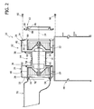
- FIGS. 1 through 4 are schematic front sections illustrating the sequence of disassembly of the centrifugal fan in a ventilation assembly according to the present invention.
- the number 10 designates a ventilation assembly for vehicles intended to be incorporated in a heating and/or air conditioning assembly for vehicles.
- the ventilation assembly 10 is to be mounted inside the vehicle dashboard. Usually, the ventilation assembly is positioned in a central area of the vehicle, between the steering column and the glove compartment located in front of the forward passenger seat.
- the ventilation assembly 10 comprises a case 12 made of plastic material wherein is housed a centrifugal ventilator 14.
- the centrifugal ventilator 14 comprises an electric motor 16 having a shaft 18 able to rotate around an axis 19. The two ends of the shaft 18 project from opposite parts of the motor 16. On a first end of the shaft 18 is keyed a first centrifugal fan 20. A second centrifugal fan, identical to the first, is keyed on the opposite end of the shaft 18.
- the case 12 of the ventilation assembly 10 comprises two air conveying sections 24, 26, each of which defines a chamber 28, 30 within which is housed a respective centrifugal fan 20, 22.
- Each of the two sections 24, 26 constitutes the stator of a centrifugal ventilator.
- Each section 24, 26 has an outer front wall 32, 34, an inner front wall 36, 38 and a circumferential wall 40, 42.
- the two inner front walls 36, 38 are distanced from each other along the axis 19.
- Each conveying section 24 has an opening 44, 46 in the outer front wall 32, 34 for the entry of the air flow.
- Each conveying section 24, 26 also has an opening for the exit of the air flow (not shown) formed in the circumferential wall 40, 42.
- the outlets of the two conveying sections 24, 26 lead to a treatment box 48 wherein the air flow is heated or cooled passing through a heater or an evaporator.
- the ventilation assembly 10 comprises two air intake boxes 50, 52 connected to the respective conveying sections 24, 26.
- Each air intake box 50, 52 comprises an inlet for the entry of the air coming from the exterior, an inlet for the entry of the air coming from the interior of the passenger compartment (recirculation) and a valve element (not shown) which enables selectively to close one or the other of the inlets.
- Each air intake box 50, 52 also has an outlet 54, 56 which communicates with the inlet 44, 46 of the respective conveying section 24, 26.
- Each fan 20, 22 has a front inlet for the entry of the air flow facing the corresponding inlet 44, 46 of the respective conveying section 24, 26.
- Each centrifugal fan 20, 22 has a plurality of fins positioned along a cylindrical surface, which, by effect of the rotation of the fan, generate a radial air flow which is collected and conveyed by the walls of the respective conveying sections 24, 26.
- the centrifugal ventilator 14 comprises a support 58 preferably made of injection-moulded plastic material, having a cylindrical seat 60 within which is inserted and fastened the electric motor 16.
- the support 58 has two radial closure walls 62, 64.
- Each radial closure wall 62, 64 has a respective annular rib 66, 68 projecting in the axial direction.
- the annular ribs 66, 68 are situated at the end of the respective radial closure wall 62, 64.
- the annular rib 68 is positioned at a greater distance from the axis 19 than the distance from the axis of the annular rib 66.
- the inner front walls 36, 38 of the conveying sections 24, 26 are provided with respective openings 70, 72.
- the inner front walls 36, 38 have, at the openings 70, 72, respective annular grooves 74, 76.
- the annular groove 74 has its own concavity oriented towards the exterior of the conveying section 24 whilst the annular groove 76 has its own concavity oriented towards the exterior in the conveying section 26.
- the distance of the groove 74 relative to the axis 19 is equal to the distance of the groove 66 relative to the same axis 19.
- the distance of the annular groove 76 relative to the axis 19 is equal to the distance of the rib 68 from the axis 19.
- the diameter of the opening 70 is greater than the outer diameter of the centrifugal fan 20 and the diameter of the opening 72 is greater than the outer diameter of the closing wall 62.
- the outer front wall 32 of the conveying section 24 has, at the opening 44, an annular groove 78 with concavity oriented towards the interior of the conveying section 24.
- the outer front edge of the centrifugal fan 20 extends to the interior of the annular groove 78.
- the outer front wall 34 of the conveying section 26 has an opening 80 with a greater diameter than the outer diameter of the closing wall 74.
- a removable annular element 82 is fastened to the outer front wall 34.
- the annular element 82 has an annular groove 84 with concavity oriented towards the interior of the conveying section 26.
- the front edge of the fan 22 is inserted in the annular groove 84.
- the annular element 82 has an outer rib 86 whereto is connected the air intake box 52.
- the annular element could be incorporated in the air intake box 52. In this case, the front end of the air intake box 52 would have the groove 84 and would be fastened directly on the outer front wall 34 of the conveying section 26.
- the two fans 20, 22 are housed within the respective conveying sections 24, 26.
- the air intake boxes 50, 52 are connected and fastened to the respective conveying sections 24, 26.
- the closing walls 62, 64 of the support 58 close the openings 70, 72 of the inner front walls 36, 38.
- Figure 1 shows the condition in which, after the removal of the screws 88, the air intake box 54 is moved away from the conveying section 26.
- the annular element 82 is removed. Naturally, this operation is not necessary if the annular element 82 is incorporated in the air intake box 52.
- the annular element 82 if it is an autonomous component, can be fastened in snap-in fashion or by means of screws to the front wall 34 of the conveying section 26.
- the reference number 90 schematically designates the screws that fasten the annular element 82 to the conveying section 26.
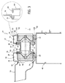
- the centrifugal ventilator 14 After the removal of the annular element 82, as shown in Figure 2, the centrifugal ventilator 14 is disassembled.
- the ventilator 14 can be fastened to the conveying section 26 by means of screws designated with the number 92 in Figure 3. After the removal of said screws (which can be accessed through the opening 80) the ventilator 14 can be extracted in the direction of its own axis 19.
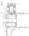
- FIG. 4 shows the ventilation assembly after the extraction of the centrifugal ventilator 14. It is readily apparent that in the solution according to the present invention the set comprising: motor support 58, electric motor 16 and centrifugal fans 20, 22 is extracted.
- the disassembly in the axial direction of the centrifugal ventilator described above enables to replace the centrifugal ventilator acting through the opening in which the glove compartment is mounted.
- the solution according to the present invention enables to assemble and disassemble the ventilator assembly in relatively simple and rapid fashion, minimising the number of components which need to be disassembled to access the ventilator.
- the ventilator may be removed from the right side of the assembly, as shown in the figures, or from the left side. Disassembling the ventilator from the left side is advantageous in particular in vehicles with right-hand drive.
Landscapes
- Engineering & Computer Science (AREA)
- Mechanical Engineering (AREA)
- General Engineering & Computer Science (AREA)
- Physics & Mathematics (AREA)
- Thermal Sciences (AREA)
- Structures Of Non-Positive Displacement Pumps (AREA)
- Air-Conditioning For Vehicles (AREA)
- Motor Or Generator Cooling System (AREA)
Priority Applications (1)
| Application Number | Priority Date | Filing Date | Title |
|---|---|---|---|
| PL06113929T PL1731339T3 (pl) | 2005-06-10 | 2006-05-15 | Zespół wentylacyjny z podwójnym wentylatorem do pojazdów |
Applications Claiming Priority (1)
| Application Number | Priority Date | Filing Date | Title |
|---|---|---|---|
| IT000405A ITTO20050405A1 (it) | 2005-06-10 | 2005-06-10 | Gruppo di ventilazione a doppia ventola per veicoli |
Publications (2)
| Publication Number | Publication Date |
|---|---|
| EP1731339A1 EP1731339A1 (en) | 2006-12-13 |
| EP1731339B1 true EP1731339B1 (en) | 2008-01-02 |
Family
ID=36874771
Family Applications (1)
| Application Number | Title | Priority Date | Filing Date |
|---|---|---|---|
| EP06113929A Not-in-force EP1731339B1 (en) | 2005-06-10 | 2006-05-15 | Double fan ventilation assembly for vehicles |
Country Status (9)
| Country | Link |
|---|---|
| EP (1) | EP1731339B1 (pt) |
| KR (1) | KR101230113B1 (pt) |
| CN (1) | CN1876415B (pt) |
| AT (1) | ATE382494T1 (pt) |
| BR (1) | BRPI0602416A (pt) |
| DE (1) | DE602006000387T2 (pt) |
| ES (1) | ES2297810T3 (pt) |
| IT (1) | ITTO20050405A1 (pt) |
| PL (1) | PL1731339T3 (pt) |
Cited By (1)
| Publication number | Priority date | Publication date | Assignee | Title |
|---|---|---|---|---|
| EP2138334A1 (en) | 2008-06-25 | 2009-12-30 | Calsonic Kansei Corporation | Air conditioning apparatus for use in a vehicle, tool and method for extraction of a component with respect to such an apparatus. |
Families Citing this family (8)
| Publication number | Priority date | Publication date | Assignee | Title |
|---|---|---|---|---|
| FR2895316B1 (fr) | 2005-12-22 | 2010-08-20 | Valeo Systemes Thermiques | Dispositif de chauffage, ventilation et/ou climatisation de vehicule comprenant un groupe moto-ventilateur demontable |
| JP4325668B2 (ja) * | 2006-12-25 | 2009-09-02 | トヨタ自動車株式会社 | 車両用空調装置 |
| FR2915134B1 (fr) * | 2007-04-23 | 2016-05-13 | Valeo Systemes Thermiques Branche Thermique Habitacle | Dispositif de ventilation,en particulier pour une installation de chauffage ou de climatisation d'un vehicule automobile |
| JP5304719B2 (ja) * | 2010-04-26 | 2013-10-02 | 株式会社デンソー | 車両用空調装置の送風ユニット |
| TWI493111B (zh) * | 2010-11-29 | 2015-07-21 | Sunonwealth Electr Mach Ind Co | 串接式馬達及具有該馬達之風扇 |
| US20140234092A1 (en) * | 2013-02-19 | 2014-08-21 | Ford Global Technologies, Llc | Dual fan coaxial flow blower housing assembly |
| CN104791270A (zh) * | 2015-03-01 | 2015-07-22 | 张宏松 | 一种纸管打腊机干燥风扇 |
| KR101995440B1 (ko) * | 2018-07-30 | 2019-07-02 | 뉴모텍(주) | 듀얼 팬 모터 |
Family Cites Families (5)
| Publication number | Priority date | Publication date | Assignee | Title |
|---|---|---|---|---|
| US2710573A (en) * | 1951-04-30 | 1955-06-14 | Trade Wind Motorfans Inc | Air handling apparatus |
| DE8914525U1 (pt) * | 1989-12-09 | 1990-01-18 | Sueddeutsche Kuehlerfabrik Julius Fr. Behr Gmbh & Co Kg, 7000 Stuttgart, De | |
| JP3758286B2 (ja) * | 1996-06-26 | 2006-03-22 | 株式会社デンソー | 送風ユニット |
| US6896478B2 (en) * | 2002-12-16 | 2005-05-24 | Visteon Global Technologies, Inc. | Dual fan blower with axial expansion |
| DE20308886U1 (de) * | 2003-06-05 | 2004-10-14 | Ebm-Papst Mulfingen Gmbh & Co. Kg | Doppel-Gebläseanordnung |
-
2005
- 2005-06-10 IT IT000405A patent/ITTO20050405A1/it unknown
-
2006
- 2006-05-15 ES ES06113929T patent/ES2297810T3/es active Active
- 2006-05-15 EP EP06113929A patent/EP1731339B1/en not_active Not-in-force
- 2006-05-15 AT AT06113929T patent/ATE382494T1/de not_active IP Right Cessation
- 2006-05-15 DE DE602006000387T patent/DE602006000387T2/de active Active
- 2006-05-15 PL PL06113929T patent/PL1731339T3/pl unknown
- 2006-06-08 KR KR1020060051416A patent/KR101230113B1/ko not_active IP Right Cessation
- 2006-06-09 BR BRPI0602416-5A patent/BRPI0602416A/pt not_active IP Right Cessation
- 2006-06-12 CN CN2006100917548A patent/CN1876415B/zh not_active Expired - Fee Related
Cited By (2)
| Publication number | Priority date | Publication date | Assignee | Title |
|---|---|---|---|---|
| EP2138334A1 (en) | 2008-06-25 | 2009-12-30 | Calsonic Kansei Corporation | Air conditioning apparatus for use in a vehicle, tool and method for extraction of a component with respect to such an apparatus. |
| JP2010006187A (ja) * | 2008-06-25 | 2010-01-14 | Calsonic Kansei Corp | 車両用空調装置および作業方法 |
Also Published As
| Publication number | Publication date |
|---|---|
| KR20060128700A (ko) | 2006-12-14 |
| DE602006000387D1 (de) | 2008-02-14 |
| CN1876415A (zh) | 2006-12-13 |
| DE602006000387T2 (de) | 2009-01-22 |
| ES2297810T3 (es) | 2008-05-01 |
| BRPI0602416A (pt) | 2007-02-21 |
| ITTO20050405A1 (it) | 2006-12-11 |
| CN1876415B (zh) | 2012-07-04 |
| ATE382494T1 (de) | 2008-01-15 |
| EP1731339A1 (en) | 2006-12-13 |
| KR101230113B1 (ko) | 2013-02-05 |
| PL1731339T3 (pl) | 2008-06-30 |
Similar Documents
| Publication | Publication Date | Title |
|---|---|---|
| EP1731339B1 (en) | Double fan ventilation assembly for vehicles | |
| US10421336B2 (en) | Suction pulser intended for a heating, ventilation and/or air-conditioning device of a motor vehicle | |
| US6789999B2 (en) | Center console dual centrifugal fan blower | |
| CN101509496B (zh) | 电动鼓风机 | |
| EP2325497A2 (en) | Open-hub centrifugal blower assembly | |
| CN109424566B (zh) | 用于车辆用空调装置的离心送风机 | |
| US9140270B2 (en) | Centrifugal fan assembly | |
| EP1769952B1 (en) | Ventilation assembly for a vehicle | |
| KR20120139727A (ko) | 원심 송풍기 조립체 | |
| JP4431130B2 (ja) | 空気入口アッセンブリ | |
| EP3335918B1 (en) | Air blowing device | |
| KR101222512B1 (ko) | 차량용 공조장치 | |
| US6206633B1 (en) | Case assembling structure of blower unit | |
| CN106739939B (zh) | 电机支撑单元和相应机动车辆加热、通风和/或空调装置 | |
| US20180105012A1 (en) | Air conditioner for vehicle | |
| WO2018180980A1 (ja) | 車両空調用送風装置 | |
| US10137756B2 (en) | Rotary door for ventilation apparatus and ventilation apparatus having the rotary door | |
| JP4950502B2 (ja) | 送風ユニット | |
| US5873779A (en) | Casting for a heating or air conditioning apparatus for a vehicle | |
| JP2018001820A (ja) | 送風ユニット | |
| US9989066B2 (en) | Low power and low noise fan-scroll with multiple split incoming air-streams | |
| RU2453967C2 (ru) | Электровентиляторный агрегат улучшенного охлаждения | |
| JP6909069B2 (ja) | 車両用空調装置の送風機 | |
| KR101276112B1 (ko) | 차량용 공조장치 | |
| JP5180696B2 (ja) | 車両用空調装置 |
Legal Events
| Date | Code | Title | Description |
|---|---|---|---|
| PUAI | Public reference made under article 153(3) epc to a published international application that has entered the european phase |
Free format text: ORIGINAL CODE: 0009012 |
|
| AK | Designated contracting states |
Kind code of ref document: A1 Designated state(s): AT BE BG CH CY CZ DE DK EE ES FI FR GB GR HU IE IS IT LI LT LU LV MC NL PL PT RO SE SI SK TR |
|
| AX | Request for extension of the european patent |
Extension state: AL BA HR MK YU |
|
| 17P | Request for examination filed |
Effective date: 20070523 |
|
| GRAP | Despatch of communication of intention to grant a patent |
Free format text: ORIGINAL CODE: EPIDOSNIGR1 |
|
| AKX | Designation fees paid |
Designated state(s): AT BE BG CH CY CZ DE DK EE ES FI FR GB GR HU IE IS IT LI LT LU LV MC NL PL PT RO SE SI SK TR |
|
| GRAS | Grant fee paid |
Free format text: ORIGINAL CODE: EPIDOSNIGR3 |
|
| GRAA | (expected) grant |
Free format text: ORIGINAL CODE: 0009210 |
|
| AK | Designated contracting states |
Kind code of ref document: B1 Designated state(s): AT BE BG CH CY CZ DE DK EE ES FI FR GB GR HU IE IS IT LI LT LU LV MC NL PL PT RO SE SI SK TR |
|
| REG | Reference to a national code |
Ref country code: GB Ref legal event code: FG4D |
|
| REG | Reference to a national code |
Ref country code: IE Ref legal event code: FG4D |
|
| REG | Reference to a national code |
Ref country code: CH Ref legal event code: EP |
|
| REF | Corresponds to: |
Ref document number: 602006000387 Country of ref document: DE Date of ref document: 20080214 Kind code of ref document: P |
|
| REG | Reference to a national code |
Ref country code: ES Ref legal event code: FG2A Ref document number: 2297810 Country of ref document: ES Kind code of ref document: T3 |
|
| PG25 | Lapsed in a contracting state [announced via postgrant information from national office to epo] |
Ref country code: SI Free format text: LAPSE BECAUSE OF FAILURE TO SUBMIT A TRANSLATION OF THE DESCRIPTION OR TO PAY THE FEE WITHIN THE PRESCRIBED TIME-LIMIT Effective date: 20080102 Ref country code: NL Free format text: LAPSE BECAUSE OF FAILURE TO SUBMIT A TRANSLATION OF THE DESCRIPTION OR TO PAY THE FEE WITHIN THE PRESCRIBED TIME-LIMIT Effective date: 20080102 |
|
| REG | Reference to a national code |
Ref country code: PL Ref legal event code: T3 |
|
| NLV1 | Nl: lapsed or annulled due to failure to fulfill the requirements of art. 29p and 29m of the patents act | ||
| ET | Fr: translation filed | ||
| PG25 | Lapsed in a contracting state [announced via postgrant information from national office to epo] |
Ref country code: FI Free format text: LAPSE BECAUSE OF FAILURE TO SUBMIT A TRANSLATION OF THE DESCRIPTION OR TO PAY THE FEE WITHIN THE PRESCRIBED TIME-LIMIT Effective date: 20080102 Ref country code: LT Free format text: LAPSE BECAUSE OF FAILURE TO SUBMIT A TRANSLATION OF THE DESCRIPTION OR TO PAY THE FEE WITHIN THE PRESCRIBED TIME-LIMIT Effective date: 20080102 Ref country code: CH Free format text: LAPSE BECAUSE OF FAILURE TO SUBMIT A TRANSLATION OF THE DESCRIPTION OR TO PAY THE FEE WITHIN THE PRESCRIBED TIME-LIMIT Effective date: 20080102 Ref country code: LI Free format text: LAPSE BECAUSE OF FAILURE TO SUBMIT A TRANSLATION OF THE DESCRIPTION OR TO PAY THE FEE WITHIN THE PRESCRIBED TIME-LIMIT Effective date: 20080102 Ref country code: IS Free format text: LAPSE BECAUSE OF FAILURE TO SUBMIT A TRANSLATION OF THE DESCRIPTION OR TO PAY THE FEE WITHIN THE PRESCRIBED TIME-LIMIT Effective date: 20080502 |
|
| REG | Reference to a national code |
Ref country code: CH Ref legal event code: PL |
|
| PG25 | Lapsed in a contracting state [announced via postgrant information from national office to epo] |
Ref country code: BG Free format text: LAPSE BECAUSE OF FAILURE TO SUBMIT A TRANSLATION OF THE DESCRIPTION OR TO PAY THE FEE WITHIN THE PRESCRIBED TIME-LIMIT Effective date: 20080402 Ref country code: AT Free format text: LAPSE BECAUSE OF FAILURE TO SUBMIT A TRANSLATION OF THE DESCRIPTION OR TO PAY THE FEE WITHIN THE PRESCRIBED TIME-LIMIT Effective date: 20080102 |
|
| PG25 | Lapsed in a contracting state [announced via postgrant information from national office to epo] |
Ref country code: LV Free format text: LAPSE BECAUSE OF FAILURE TO SUBMIT A TRANSLATION OF THE DESCRIPTION OR TO PAY THE FEE WITHIN THE PRESCRIBED TIME-LIMIT Effective date: 20080102 Ref country code: BE Free format text: LAPSE BECAUSE OF FAILURE TO SUBMIT A TRANSLATION OF THE DESCRIPTION OR TO PAY THE FEE WITHIN THE PRESCRIBED TIME-LIMIT Effective date: 20080102 Ref country code: PT Free format text: LAPSE BECAUSE OF FAILURE TO SUBMIT A TRANSLATION OF THE DESCRIPTION OR TO PAY THE FEE WITHIN THE PRESCRIBED TIME-LIMIT Effective date: 20080602 |
|
| PG25 | Lapsed in a contracting state [announced via postgrant information from national office to epo] |
Ref country code: DK Free format text: LAPSE BECAUSE OF FAILURE TO SUBMIT A TRANSLATION OF THE DESCRIPTION OR TO PAY THE FEE WITHIN THE PRESCRIBED TIME-LIMIT Effective date: 20080102 Ref country code: CZ Free format text: LAPSE BECAUSE OF FAILURE TO SUBMIT A TRANSLATION OF THE DESCRIPTION OR TO PAY THE FEE WITHIN THE PRESCRIBED TIME-LIMIT Effective date: 20080102 Ref country code: SK Free format text: LAPSE BECAUSE OF FAILURE TO SUBMIT A TRANSLATION OF THE DESCRIPTION OR TO PAY THE FEE WITHIN THE PRESCRIBED TIME-LIMIT Effective date: 20080102 Ref country code: SE Free format text: LAPSE BECAUSE OF FAILURE TO SUBMIT A TRANSLATION OF THE DESCRIPTION OR TO PAY THE FEE WITHIN THE PRESCRIBED TIME-LIMIT Effective date: 20080402 |
|
| PLBE | No opposition filed within time limit |
Free format text: ORIGINAL CODE: 0009261 |
|
| STAA | Information on the status of an ep patent application or granted ep patent |
Free format text: STATUS: NO OPPOSITION FILED WITHIN TIME LIMIT |
|
| PG25 | Lapsed in a contracting state [announced via postgrant information from national office to epo] |
Ref country code: RO Free format text: LAPSE BECAUSE OF FAILURE TO SUBMIT A TRANSLATION OF THE DESCRIPTION OR TO PAY THE FEE WITHIN THE PRESCRIBED TIME-LIMIT Effective date: 20080102 |
|
| 26N | No opposition filed |
Effective date: 20081003 |
|
| PG25 | Lapsed in a contracting state [announced via postgrant information from national office to epo] |
Ref country code: MC Free format text: LAPSE BECAUSE OF NON-PAYMENT OF DUE FEES Effective date: 20080531 |
|
| PG25 | Lapsed in a contracting state [announced via postgrant information from national office to epo] |
Ref country code: EE Free format text: LAPSE BECAUSE OF FAILURE TO SUBMIT A TRANSLATION OF THE DESCRIPTION OR TO PAY THE FEE WITHIN THE PRESCRIBED TIME-LIMIT Effective date: 20080102 |
|
| PG25 | Lapsed in a contracting state [announced via postgrant information from national office to epo] |
Ref country code: IE Free format text: LAPSE BECAUSE OF NON-PAYMENT OF DUE FEES Effective date: 20080515 |
|
| PG25 | Lapsed in a contracting state [announced via postgrant information from national office to epo] |
Ref country code: CY Free format text: LAPSE BECAUSE OF FAILURE TO SUBMIT A TRANSLATION OF THE DESCRIPTION OR TO PAY THE FEE WITHIN THE PRESCRIBED TIME-LIMIT Effective date: 20080102 |
|
| PG25 | Lapsed in a contracting state [announced via postgrant information from national office to epo] |
Ref country code: IT Free format text: LAPSE BECAUSE OF FAILURE TO SUBMIT A TRANSLATION OF THE DESCRIPTION OR TO PAY THE FEE WITHIN THE PRESCRIBED TIME-LIMIT Effective date: 20080102 |
|
| PG25 | Lapsed in a contracting state [announced via postgrant information from national office to epo] |
Ref country code: HU Free format text: LAPSE BECAUSE OF FAILURE TO SUBMIT A TRANSLATION OF THE DESCRIPTION OR TO PAY THE FEE WITHIN THE PRESCRIBED TIME-LIMIT Effective date: 20080703 Ref country code: LU Free format text: LAPSE BECAUSE OF NON-PAYMENT OF DUE FEES Effective date: 20080515 |
|
| PG25 | Lapsed in a contracting state [announced via postgrant information from national office to epo] |
Ref country code: GR Free format text: LAPSE BECAUSE OF FAILURE TO SUBMIT A TRANSLATION OF THE DESCRIPTION OR TO PAY THE FEE WITHIN THE PRESCRIBED TIME-LIMIT Effective date: 20080403 |
|
| PGFP | Annual fee paid to national office [announced via postgrant information from national office to epo] |
Ref country code: ES Payment date: 20120518 Year of fee payment: 7 |
|
| PGFP | Annual fee paid to national office [announced via postgrant information from national office to epo] |
Ref country code: GB Payment date: 20130521 Year of fee payment: 8 |
|
| PGFP | Annual fee paid to national office [announced via postgrant information from national office to epo] |
Ref country code: TR Payment date: 20130425 Year of fee payment: 8 Ref country code: FR Payment date: 20130620 Year of fee payment: 8 Ref country code: PL Payment date: 20130409 Year of fee payment: 8 |
|
| PGFP | Annual fee paid to national office [announced via postgrant information from national office to epo] |
Ref country code: DE Payment date: 20130731 Year of fee payment: 8 |
|
| REG | Reference to a national code |
Ref country code: DE Ref legal event code: R119 Ref document number: 602006000387 Country of ref document: DE |
|
| GBPC | Gb: european patent ceased through non-payment of renewal fee |
Effective date: 20140515 |
|
| REG | Reference to a national code |
Ref country code: DE Ref legal event code: R119 Ref document number: 602006000387 Country of ref document: DE Effective date: 20141202 |
|
| REG | Reference to a national code |
Ref country code: FR Ref legal event code: ST Effective date: 20150130 |
|
| PG25 | Lapsed in a contracting state [announced via postgrant information from national office to epo] |
Ref country code: DE Free format text: LAPSE BECAUSE OF NON-PAYMENT OF DUE FEES Effective date: 20141202 |
|
| PG25 | Lapsed in a contracting state [announced via postgrant information from national office to epo] |
Ref country code: GB Free format text: LAPSE BECAUSE OF NON-PAYMENT OF DUE FEES Effective date: 20140515 Ref country code: FR Free format text: LAPSE BECAUSE OF NON-PAYMENT OF DUE FEES Effective date: 20140602 |
|
| REG | Reference to a national code |
Ref country code: ES Ref legal event code: FD2A Effective date: 20150729 |
|
| PG25 | Lapsed in a contracting state [announced via postgrant information from national office to epo] |
Ref country code: PL Free format text: LAPSE BECAUSE OF NON-PAYMENT OF DUE FEES Effective date: 20140515 |
|
| REG | Reference to a national code |
Ref country code: PL Ref legal event code: LAPE |
|
| PG25 | Lapsed in a contracting state [announced via postgrant information from national office to epo] |
Ref country code: ES Free format text: LAPSE BECAUSE OF NON-PAYMENT OF DUE FEES Effective date: 20140516 |
|
| PG25 | Lapsed in a contracting state [announced via postgrant information from national office to epo] |
Ref country code: TR Free format text: LAPSE BECAUSE OF NON-PAYMENT OF DUE FEES Effective date: 20140515 |