EP1730080B1 - Elektrodenanordnung für eine elektrochemische behandlung von flüssigkeiten mit einer geringen leitfähigkeit - Google Patents
Elektrodenanordnung für eine elektrochemische behandlung von flüssigkeiten mit einer geringen leitfähigkeit Download PDFInfo
- Publication number
- EP1730080B1 EP1730080B1 EP05736207A EP05736207A EP1730080B1 EP 1730080 B1 EP1730080 B1 EP 1730080B1 EP 05736207 A EP05736207 A EP 05736207A EP 05736207 A EP05736207 A EP 05736207A EP 1730080 B1 EP1730080 B1 EP 1730080B1
- Authority
- EP
- European Patent Office
- Prior art keywords
- electrodes
- electrode assembly
- solid electrolyte
- pressure
- polymeric solid
- Prior art date
- Legal status (The legal status is an assumption and is not a legal conclusion. Google has not performed a legal analysis and makes no representation as to the accuracy of the status listed.)
- Expired - Lifetime
Links
Images


Classifications
-
- C—CHEMISTRY; METALLURGY
- C02—TREATMENT OF WATER, WASTE WATER, SEWAGE, OR SLUDGE
- C02F—TREATMENT OF WATER, WASTE WATER, SEWAGE, OR SLUDGE
- C02F1/00—Treatment of water, waste water, or sewage
- C02F1/46—Treatment of water, waste water, or sewage by electrochemical methods
- C02F1/461—Treatment of water, waste water, or sewage by electrochemical methods by electrolysis
- C02F1/46104—Devices therefor; Their operating or servicing
- C02F1/46109—Electrodes
-
- C—CHEMISTRY; METALLURGY
- C25—ELECTROLYTIC OR ELECTROPHORETIC PROCESSES; APPARATUS THEREFOR
- C25B—ELECTROLYTIC OR ELECTROPHORETIC PROCESSES FOR THE PRODUCTION OF COMPOUNDS OR NON-METALS; APPARATUS THEREFOR
- C25B11/00—Electrodes; Manufacture thereof not otherwise provided for
- C25B11/02—Electrodes; Manufacture thereof not otherwise provided for characterised by shape or form
- C25B11/036—Bipolar electrodes
-
- C—CHEMISTRY; METALLURGY
- C25—ELECTROLYTIC OR ELECTROPHORETIC PROCESSES; APPARATUS THEREFOR
- C25B—ELECTROLYTIC OR ELECTROPHORETIC PROCESSES FOR THE PRODUCTION OF COMPOUNDS OR NON-METALS; APPARATUS THEREFOR
- C25B9/00—Cells or assemblies of cells; Constructional parts of cells; Assemblies of constructional parts, e.g. electrode-diaphragm assemblies; Process-related cell features
- C25B9/01—Electrolytic cells characterised by shape or form
-
- C—CHEMISTRY; METALLURGY
- C25—ELECTROLYTIC OR ELECTROPHORETIC PROCESSES; APPARATUS THEREFOR
- C25B—ELECTROLYTIC OR ELECTROPHORETIC PROCESSES FOR THE PRODUCTION OF COMPOUNDS OR NON-METALS; APPARATUS THEREFOR
- C25B9/00—Cells or assemblies of cells; Constructional parts of cells; Assemblies of constructional parts, e.g. electrode-diaphragm assemblies; Process-related cell features
- C25B9/60—Constructional parts of cells
- C25B9/65—Means for supplying current; Electrode connections; Electric inter-cell connections
-
- C—CHEMISTRY; METALLURGY
- C25—ELECTROLYTIC OR ELECTROPHORETIC PROCESSES; APPARATUS THEREFOR
- C25B—ELECTROLYTIC OR ELECTROPHORETIC PROCESSES FOR THE PRODUCTION OF COMPOUNDS OR NON-METALS; APPARATUS THEREFOR
- C25B9/00—Cells or assemblies of cells; Constructional parts of cells; Assemblies of constructional parts, e.g. electrode-diaphragm assemblies; Process-related cell features
- C25B9/70—Assemblies comprising two or more cells
- C25B9/73—Assemblies comprising two or more cells of the filter-press type
- C25B9/75—Assemblies comprising two or more cells of the filter-press type having bipolar electrodes
-
- C—CHEMISTRY; METALLURGY
- C25—ELECTROLYTIC OR ELECTROPHORETIC PROCESSES; APPARATUS THEREFOR
- C25B—ELECTROLYTIC OR ELECTROPHORETIC PROCESSES FOR THE PRODUCTION OF COMPOUNDS OR NON-METALS; APPARATUS THEREFOR
- C25B9/00—Cells or assemblies of cells; Constructional parts of cells; Assemblies of constructional parts, e.g. electrode-diaphragm assemblies; Process-related cell features
- C25B9/70—Assemblies comprising two or more cells
- C25B9/73—Assemblies comprising two or more cells of the filter-press type
- C25B9/77—Assemblies comprising two or more cells of the filter-press type having diaphragms
-
- C—CHEMISTRY; METALLURGY
- C02—TREATMENT OF WATER, WASTE WATER, SEWAGE, OR SLUDGE
- C02F—TREATMENT OF WATER, WASTE WATER, SEWAGE, OR SLUDGE
- C02F1/00—Treatment of water, waste water, or sewage
- C02F1/46—Treatment of water, waste water, or sewage by electrochemical methods
- C02F1/461—Treatment of water, waste water, or sewage by electrochemical methods by electrolysis
- C02F1/467—Treatment of water, waste water, or sewage by electrochemical methods by electrolysis by electrochemical disinfection; by electrooxydation or by electroreduction
- C02F1/4672—Treatment of water, waste water, or sewage by electrochemical methods by electrolysis by electrochemical disinfection; by electrooxydation or by electroreduction by electrooxydation
-
- C—CHEMISTRY; METALLURGY
- C02—TREATMENT OF WATER, WASTE WATER, SEWAGE, OR SLUDGE
- C02F—TREATMENT OF WATER, WASTE WATER, SEWAGE, OR SLUDGE
- C02F1/00—Treatment of water, waste water, or sewage
- C02F1/46—Treatment of water, waste water, or sewage by electrochemical methods
- C02F1/461—Treatment of water, waste water, or sewage by electrochemical methods by electrolysis
- C02F1/46104—Devices therefor; Their operating or servicing
- C02F1/46109—Electrodes
- C02F2001/46133—Electrodes characterised by the material
- C02F2001/46138—Electrodes comprising a substrate and a coating
-
- C—CHEMISTRY; METALLURGY
- C02—TREATMENT OF WATER, WASTE WATER, SEWAGE, OR SLUDGE
- C02F—TREATMENT OF WATER, WASTE WATER, SEWAGE, OR SLUDGE
- C02F2103/00—Nature of the water, waste water, sewage or sludge to be treated
- C02F2103/02—Non-contaminated water, e.g. for industrial water supply
- C02F2103/04—Non-contaminated water, e.g. for industrial water supply for obtaining ultra-pure water
-
- C—CHEMISTRY; METALLURGY
- C02—TREATMENT OF WATER, WASTE WATER, SEWAGE, OR SLUDGE
- C02F—TREATMENT OF WATER, WASTE WATER, SEWAGE, OR SLUDGE
- C02F2201/00—Apparatus for treatment of water, waste water or sewage
- C02F2201/46—Apparatus for electrochemical processes
- C02F2201/461—Electrolysis apparatus
- C02F2201/46105—Details relating to the electrolytic devices
- C02F2201/46195—Cells containing solid electrolyte
Definitions
- the invention relates to an electrode assembly for an electrochemical treatment of liquids with a low conductivity, with electrodes, between which a polymer solid electrolyte is arranged, which are pressed against each other by means of a pressure device and which are formed so that the arrangement can be flowed through by the liquid.
- a main field of application for such an electrode arrangement consists in water systems in which pure water or ultrapure water in particular are to be made germ-free and algae-free.
- the water system can consist of pipelines, catch basins, open bathrooms, etc.
- Electrode arrangements of the type mentioned above are used in particular for the disinfection of rainwater, the disinfection of Reinsfinrasser circuits in the semiconductor and pharmaceutical industries, the elimination of organic loads in rinsing waters, the treatment of water for the food industry and cosmetics industry and for use in all types of industrial cooling water circuits to prevent algae growth or growth of bacteria or to break down in high contaminations.
- oxidizing agents can be produced which oxidize and thus kill germs or inactivate them.
- the electrochemical generation of oxidants has the advantage that an adaptation to the particular application is possible in principle.
- oxidizing agents when a water system is already impoverished or biologically contaminated and is to be cleaned and disinfected.
- the water system can be kept permanently in the disinfected and cleaned state, which only requires temporary and only a small need for oxidants.
- a varying demand for oxidants also arises when a water system is burdened by an accident involving a high rate of organic cargo. The same applies to the filling of a tank, where initially a high oxidant production is required to accomplish the initial disinfection, while subsequently only small amounts of oxidant are sufficient to maintain the disinfected state.
- electrochemical processes are suitable to meet the different requirements for the production of oxidants. Because the oxidant production can be controlled by the supply of electricity.
- the electrical potential of one electrode is brought very close to the other electrode, wherein between the surface of the polymer solid electrolyte and the immediately adjacent Electrode is a water film, which is thus exposed to high current densities.
- the Fischer cells were originally constructed with lead oxide electrodes.
- the use of a lead oxide anode has the further disadvantage that the electrode decomposes in water if it is not kept at a protection potential.
- the use of an electrode assembly with a lead oxide anode is therefore possible only in continuous operation, so that eliminates the option to use the appropriate cell only when needed.
- an electrochemical ozone generator in the form of a small portable device having a tubular housing with an open front end.
- a extending over the cross section of the tubular housing cathode is fixed, on which a solid electrolyte membrane and an anode rest.
- the anode is contacted with a contact pin which communicates with the positive pole of a battery, which in turn is supported at the other end of the housing via a compression spring.
- the pressure force between the electrodes via the support to housing parts is effected.
- the present invention has for its object, an electrode assembly of the type mentioned in such a way that it allows an effective construction of a corresponding electrolytic cell and still easy to build and handle.
- an electrode assembly of the type mentioned in the invention is characterized in that the pressure device is formed by a clamping device, which is supported directly on the electrodes so that a pressing force is exerted by the tension directly on the electrodes themselves.
- the electrode assembly according to the invention thus requires for the pressure of the electrodes against the polymeric solid electrolyte used between the electrodes no special housing arrangement with elaborate pressure plates, sondem only a pressure device, which is directly connected to the electrodes and relates the pressure force from the rather relatively low mechanical stability of the electrodes ,
- the invention is based on the finding that an effective electrode arrangement-in contrast to the idea of the expert world that has existed for decades-can also be realized without a very high contact force of the electrodes against the polymer solid electrolyte.
- an expanded metal grid as the carrier material of an electrode, which is coated, for example, with a doped diamond layer.
- a plastic screw can be inserted through until the head of the plastic screw rests against the electrode.
- the clamping of the two electrodes in the direction of the polymer solid electrolyte can then be carried out by screwing a nut on the bolt, which protrudes through the two electrodes and the intermediate solid electrolyte.
- the polymeric solid electrolyte preferably in the form of a membrane, also has flow openings. It is also possible to ensure the flow through the gap between the electrodes in that the polymeric solid electrolyte is arranged in spaced-apart strips in the space between the electrodes. In a further development of this idea, the polymeric solid electrolyte can also be arranged in area pieces spaced apart on all sides in the intermediate space, so that through-flow of the intermediate space in different directions is ensured.
- the polymeric solid electrolyte can be inserted in the form of a membrane between the electrodes.
- the polymeric solid electrolyte it will be expedient for the polymeric solid electrolyte to be applied to one of the electrodes as a surface layer.
- the electrode arrangement according to the invention requires no complicated contact pressure generation, it is readily possible to construct a stack with the electrode arrangement, which enables an effective electrolysis device also for higher flow rates. Since the pressure device is supported on the electrodes themselves, it is readily possible to arrange numerous electrodes with a arranged between them polymeric solid electrolyte to a stack. It is particularly expedient if the electrodes are provided with the aid of over their common surface protruding contact lugs for electrical contacting. In this case, the contact lugs of the anodes in the stack on the one hand and the cathodes in the stack on the other hand be aligned with each other to facilitate a common contact, for example, by a through inserted through openings of the contact lugs contact rod.
- the electrode arrangement according to the invention also allows, in a surprisingly simple manner, the departure from the usual flat electrodes.
- the strip can be attached around the two electrodes in each case in the form of a figure eight, wherein the looping takes place with a certain bias to ensure intimate contact.
- the pressing of the two electrodes against the strip portions of the polymer solid electrolyte located between the electrodes can be effected for example by means of a wire-shaped material wound around the electrodes with ends twisted together to produce the pressure.
- the wire-shaped material may preferably be an insulating material or be applied to the electrodes via an insulating layer.
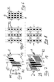
- a first electrode 1 serves as a cathode, while the second electrode 2 acts as an anode. Both electrodes 1, 2 are formed flat with a rectangular cross-section and have the same surface shape. Between the two electrodes 1, 2 there is a polymeric solid electrolyte 3 in the form of a membrane 31, the area of which corresponds to the surface of the electrodes 1, 2.
- the membrane 31 is provided in its four corner regions, each with a through opening 4.
- the membrane has, for example, a thickness between 0.4 and 0.8 mm.
- the electrodes 1, 2 are provided outside the rectangular surface of the expanded metal mesh 11, 21, each with a protruding from the surface contact lug 5, 6. Both contact lugs have a passage opening 7, 8.
- FIG. 2 illustrates that the electrodes 1, 2 formed from the expanded metal lattices 11, 21 are pressed against one another by means of a tensioning device 9, in each case with a solid electrolyte 3 therebetween, wherein the tensioning device 9 extends over four electrode assemblies 1, 2, 3 assembled into a stack ,
- the bracing is done by means of nuts 10 which are clamped on the threaded bolt 9 against the electrodes 1, 2.
- FIG. 3 illustrates in a perspective view that the electrodes 1, 2 are each connected to different poles of the supply voltages.
- the electrodes 1, 2 are formed in the embodiment shown in Figures 1 to 3 with a support in the form of an expanded metal mesh 11, 21 and coated with a doped diamond layer. It is also possible to apply differently sized supply voltages to the electrodes 1, 2.
- FIG. 4 shows a modified embodiment in which the electrodes 1, 2 are formed with metal plates 12, 22 which are coated with a doped diamond layer.
- the electrodes have passage openings 41 in their corner regions, through which threaded bolts 9 can be pushed in the manner described with reference to FIGS. 2 and 3.
- the polymeric electrolyte 3 is formed in this embodiment by vertically standing, parallel spaced strip 32.
- the top view of FIG. 5 illustrates that the electrode arrangements in the stack formed can be traversed perpendicularly to the drawing plane due to the strips 32.
- the stack arrangement shown in Figure 6 consists of four identical electrodes 1, which are separated from each other by a solid electrolyte 3, here in the form of strips 32.
- the contacting takes place here with different polarities only at the two outer electrodes 1, whereby the middle electrodes occupy correspondingly stepped potentials.
- Such an arrangement, in which the central electrodes act both as an anode (to one side) and as a cathode, is also referred to as a bipolar arrangement.
- the exemplary embodiment illustrated in FIG. 7 differs from the exemplary embodiment according to FIG. 4 only in that it uses as carrier of the electrodes 1, 2 with metallic plates 13, 23 which are provided with horizontal slit-shaped passage openings 42, which pass through the electrodes 1, 2 allow. Accordingly, the arrows in Figure 8 show that in addition to the vertical flow (perpendicular to the plane), a flow through the electrode assemblies in the stacking direction is possible.
- the polymeric solid electrolyte 3 is applied in the form of circular surface sections 33 to the surface of the second electrode 2, which faces the first electrode 1.
- the polymeric electrolyte 3 is thus laminated directly onto the electrode 2.
- the plan view of a multiple electrode arrangement in FIG. 10 shows that the gap between the electrodes 1, 2 can be flowed through horizontally and vertically, since the surface sections 33 are spaced from one another on all sides, resulting in flow-through regions in the gaps.
- FIG. 11 illustrates in an enlarged schematic representation the contacting of the electrodes 1, 2 with the aid of the contact lugs 5, 6 and the passage openings 7, 8 located therein.
- the contact lugs 5, 6 of the respectively identically polarized electrodes 1, 2 are aligned with one another (in FIG. 11 shows contact lugs 5, 6 only for the two rear electrodes 1, 2 of the stack).
- the contact lugs 5 of the first electrodes 1 can be contacted to one another by a contact pin (not shown) inserted through the mutually aligned through openings 7, and therefore together with a pole of the supply voltage connectable.
- the contacting of the other electrodes 2 takes place via the contact lugs 6 and the passage openings 8 situated therein which are aligned with one another.
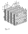
- FIG 12 illustrates the structure of a treatment cell 100, wherein for the sake of clarity, only the An oden 2 of the electrode assemblies are shown, which are contacted via their mutually aligned contact lugs 5.
- the cell 100 has a housing 101 having an inlet opening 102 for the water to be purified.
- the water to be purified flows in the housing 101 from the bottom up into the region of the electrodes 2 and exits from the region of the electrodes 2 laterally to leave the housing 101 in a purified form via the outlet openings 103.
- ventilation slots 104 In the upper part of the housing 101 there are ventilation slots 104.
- Figure 13 shows a different arrangement of the electrodes 1, 2, which are formed in this embodiment as rod-shaped electrodes 14, 24.
- the solid electrolyte 3 which in the form of a long strip 34 meandering form the shape of an "eight", around the electrodes 1, 2 is wound with a bias, so that the strip 34, the electrodes 1, 2nd already pulling against each other.
- the pressing of the electrodes against each other or against the lying between them portions of the solid electrolyte 3 is effected by two placed around the electrodes 1, 2 loops 91 of a wire-shaped insulating material, which are contractible by means of twisted ends, so the electrodes 1, 2 against each other to draw.
- the contacting of the electrodes 1, 2 takes place at the front ends with contact pieces 51, 61.
- Such a configuration of the electrode arrangement is particularly suitable for water purification in pipe systems.
Landscapes
- Chemical & Material Sciences (AREA)
- Engineering & Computer Science (AREA)
- Chemical Kinetics & Catalysis (AREA)
- Electrochemistry (AREA)
- Organic Chemistry (AREA)
- Materials Engineering (AREA)
- Metallurgy (AREA)
- Life Sciences & Earth Sciences (AREA)
- General Chemical & Material Sciences (AREA)
- Hydrology & Water Resources (AREA)
- Environmental & Geological Engineering (AREA)
- Water Supply & Treatment (AREA)
- Electrodes For Compound Or Non-Metal Manufacture (AREA)
- Water Treatment By Electricity Or Magnetism (AREA)
- Battery Electrode And Active Subsutance (AREA)
- Electroplating Methods And Accessories (AREA)
Applications Claiming Priority (2)
| Application Number | Priority Date | Filing Date | Title |
|---|---|---|---|
| DE102004015680A DE102004015680A1 (de) | 2004-03-26 | 2004-03-26 | Elektrodenanordnung für eine elektrochemische Behandlung von Flüssigkeiten mit einer geringen Leitfähigkeit |
| PCT/DE2005/000556 WO2005095282A1 (de) | 2004-03-26 | 2005-03-24 | Elektrodenanordnung für eine elektrochemische behandlung von flüssigkeiten mit einer geringen leitfähigkeit |
Publications (2)
| Publication Number | Publication Date |
|---|---|
| EP1730080A1 EP1730080A1 (de) | 2006-12-13 |
| EP1730080B1 true EP1730080B1 (de) | 2008-01-16 |
Family
ID=34965869
Family Applications (1)
| Application Number | Title | Priority Date | Filing Date |
|---|---|---|---|
| EP05736207A Expired - Lifetime EP1730080B1 (de) | 2004-03-26 | 2005-03-24 | Elektrodenanordnung für eine elektrochemische behandlung von flüssigkeiten mit einer geringen leitfähigkeit |
Country Status (8)
| Country | Link |
|---|---|
| US (1) | US7704353B2 (https=) |
| EP (1) | EP1730080B1 (https=) |
| JP (1) | JP2007530250A (https=) |
| AT (1) | ATE384026T1 (https=) |
| CA (1) | CA2560910A1 (https=) |
| DE (2) | DE102004015680A1 (https=) |
| ES (1) | ES2301008T3 (https=) |
| WO (1) | WO2005095282A1 (https=) |
Cited By (6)
| Publication number | Priority date | Publication date | Assignee | Title |
|---|---|---|---|---|
| DE102012020495A1 (de) | 2012-10-13 | 2014-04-17 | Peter Weißbach | Elektrolysezelle und Einrichtung zur Zerlegung von Wasser |
| DE102014002450A1 (de) | 2014-02-25 | 2015-08-27 | Areva Gmbh | Verfahren zum oxidativen Abbau von stickstoffhaltigen Verbindungen in Abwässern |
| DE102014203372A1 (de) | 2014-02-25 | 2015-08-27 | Condias Gmbh | Elektrodenanordnung für eine elektrochemische Behandlung einer Flüssigkeit |
| DE102014203376A1 (de) | 2014-02-25 | 2015-08-27 | Condias Gmbh | Verfahren zum Herstellen von ozonisiertem Wasser |
| DE102015122486A1 (de) | 2015-12-22 | 2017-06-22 | Coulomb Water Technology GmbH | Elektrodenanordnung für eine Elektrolysezelle |
| WO2022135731A1 (en) | 2020-12-24 | 2022-06-30 | Framatome Gmbh | Mineralization of organic compounds with boron-doped-diamond electrode during radionuclides stripping process |
Families Citing this family (35)
| Publication number | Priority date | Publication date | Assignee | Title |
|---|---|---|---|---|
| DE202005003720U1 (de) * | 2005-03-04 | 2006-07-13 | Condias Gmbh | System zur Desinfektion von Flüssigkeiten mit einer geringen Leitfähigkeit |
| DE102006038557A1 (de) * | 2006-08-17 | 2008-04-17 | Eilenburger Elektrolyse- Und Umwelttechnik Gmbh | Verfahren und Vorrichtung zur oxidativen elektrochemischen Behandlung wässriger Lösungen |
| GB0622483D0 (en) * | 2006-11-10 | 2006-12-20 | Element Six Ltd | Electrochemical apparatus having a forced flow arrangement |
| GB0622482D0 (en) | 2006-11-10 | 2006-12-20 | Element Six Ltd | Diamond electrode |
| JP4460590B2 (ja) * | 2007-06-22 | 2010-05-12 | ペルメレック電極株式会社 | 導電性ダイヤモンド電極構造体及びフッ素含有物質の電解合成方法 |
| DE102007042171A1 (de) | 2007-09-05 | 2009-03-12 | Eilenburger Elektrolyse- Und Umwelttechnik Gmbh | Elektrolysezelle mit hoher Stromkapazität zur Herstellung eines Ozon-Sauerstoffgemisches |
| US20100101010A1 (en) * | 2008-10-24 | 2010-04-29 | Watkins Manufacturing Corporation | Chlorinator for portable spas |
| DE102009005011A1 (de) | 2009-01-17 | 2010-07-22 | Eilenburger Elektrolyse- Und Umwelttechnik Gmbh | Verfahren und Vorrichtung zur elektrochemischen Desinfektion von Trink- und Brauchwasser mit hohen Härtegehalten |
| US8266736B2 (en) * | 2009-07-16 | 2012-09-18 | Watkins Manufacturing Corporation | Drop-in chlorinator for portable spas |
| DE102009039290A1 (de) | 2009-08-31 | 2011-03-03 | Eilenburger Elektrolyse- Und Umwelttechnik Gmbh | Verfahren und Vorrichtung zur Herstellung von Ozon und/oder zum oxidativen Abbau von Wasserinhaltsstoffen in natürlichen, elektrisch leitenden Wässern |
| JP5113891B2 (ja) * | 2010-04-30 | 2013-01-09 | アクアエコス株式会社 | オゾン水製造装置、オゾン水製造方法、殺菌方法及び廃水・廃液処理方法 |
| JP5113892B2 (ja) * | 2010-04-30 | 2013-01-09 | アクアエコス株式会社 | 膜−電極接合体、これを用いる電解セル、オゾン水製造装置、オゾン水製造方法、殺菌方法及び廃水・廃液処理方法 |
| CN103328690B (zh) | 2010-12-03 | 2016-08-31 | 电解臭氧有限公司 | 用于臭氧生成的电解池 |
| EP2646373A1 (de) | 2010-12-03 | 2013-10-09 | Brita GmbH | Elektrolysezelle zum erzeugen von ozon zur behandlung einer flüssigkeit |
| EP2697730A4 (en) | 2011-04-15 | 2015-04-15 | Advanced Diamond Technologies Inc | ELECTROCHEMICAL SYSTEM AND METHOD FOR PROPORTION OF OXIDIZERS AT HIGH CURRENT DENSITY |
| US9440866B2 (en) | 2011-06-06 | 2016-09-13 | Axine Water Technologies | Efficient treatment of wastewater using electrochemical cell |
| DE102012011314A1 (de) | 2012-06-06 | 2013-12-12 | Manfred Völker | Elektrochemischer Ozonerzeuger undWasserstoff-Generator |
| AU2013351879C1 (en) | 2012-12-02 | 2019-08-08 | Axine Water Technologies Inc. | Method for imparting filtering capability in electrolytic cell for wastewater treatment |
| KR102128134B1 (ko) | 2012-12-03 | 2020-06-30 | 악신 워터 테크놀로지스 아이엔씨. | 전기화학 전지를 이용하는 효율적인 폐수 처리 |
| US9222178B2 (en) | 2013-01-22 | 2015-12-29 | GTA, Inc. | Electrolyzer |
| US8808512B2 (en) | 2013-01-22 | 2014-08-19 | GTA, Inc. | Electrolyzer apparatus and method of making it |
| US11085122B2 (en) | 2014-06-26 | 2021-08-10 | Vapor Technologies, Inc. | Diamond coated electrodes for electrochemical processing and applications thereof |
| US10239772B2 (en) | 2015-05-28 | 2019-03-26 | Advanced Diamond Technologies, Inc. | Recycling loop method for preparation of high concentration ozone |
| US10696570B2 (en) | 2016-01-15 | 2020-06-30 | Axine Water Technologies Inc. | Electrochemical cell for wastewater treatment with increased removal rates of pollutants |
| EP3529397A4 (en) | 2016-10-20 | 2020-06-24 | Advanced Diamond Technologies, Inc. | OZONE GENERATORS, METHOD FOR PRODUCING OZONE GENERATORS AND METHOD FOR PRODUCING OZONE |
| EP3434650A1 (de) | 2017-07-24 | 2019-01-30 | Geberit International AG | Elektrodenanordnung |
| WO2020252242A1 (en) | 2019-06-12 | 2020-12-17 | Phosphorus Free Water Solutions, Llc | Removal of materials from water |
| US12351492B2 (en) | 2019-06-12 | 2025-07-08 | Nuquatic, Llc | Removal of materials from water |
| US12012661B2 (en) | 2020-06-27 | 2024-06-18 | Aquamox Inc. | Electrolytic generators |
| CN111646607A (zh) * | 2020-07-07 | 2020-09-11 | 上海博丹环境工程技术股份有限公司 | 一种可适用于低盐条件的有机废水电化学氧化处理的方法以及系统 |
| DE102020133770A1 (de) | 2020-12-16 | 2022-06-23 | Forschungszentrum Jülich GmbH | Anordnung elektrochemischer Zellen |
| US11401181B1 (en) | 2021-03-02 | 2022-08-02 | Phosphorus Free Water Solutions, Llc | Galvanic process for treating aqueous compositions |
| AU2024252894A1 (en) | 2023-04-05 | 2025-11-06 | Nuquatic, Llc | Treatment of aqueous composition with metal component |
| WO2024211729A1 (en) | 2023-04-05 | 2024-10-10 | Nuquatic, Llc | Removal of fluoro alkyl compounds from water using galvanic cell |
| DE102023123611A1 (de) * | 2023-09-01 | 2025-03-06 | Schneider Gmbh & Co. Kg | Elektrodenanordnung für eine elektro-chemische Behandlung von Flüssigkeiten |
Family Cites Families (14)
| Publication number | Priority date | Publication date | Assignee | Title |
|---|---|---|---|---|
| US4244802A (en) * | 1979-06-11 | 1981-01-13 | Diamond Shamrock Corporation | Monopolar membrane cell having metal laminate cell body |
| DE4227732C2 (de) * | 1992-08-21 | 1996-05-02 | Fischer Labor Und Verfahrenste | Elektrolysezelle, insbesondere zur Erzeugung von Ozon, mit einer den Anoden- und Kathodenraum voneinander trennenden Feststoffelektrolytmembran |
| US5972196A (en) * | 1995-06-07 | 1999-10-26 | Lynntech, Inc. | Electrochemical production of ozone and hydrogen peroxide |
| US5635039A (en) * | 1993-07-13 | 1997-06-03 | Lynntech, Inc. | Membrane with internal passages to permit fluid flow and an electrochemical cell containing the same |
| US5527436A (en) * | 1994-11-21 | 1996-06-18 | Arco Chemical Technology, L.P. | Akylene oxide production |
| DE29504323U1 (de) | 1995-03-17 | 1996-07-25 | Beyer, Wolfgang, 53359 Rheinbach | Elektrolysezelle zum Herstellen von Ozon bzw. Sauerstoff |
| US5876575A (en) * | 1995-09-05 | 1999-03-02 | Kump; Joseph A. | Method and apparatus for treatment of water |
| US5795450A (en) * | 1997-03-04 | 1998-08-18 | Shinko Pantec Co., Ltd. | Apparatus for producing hydrogen and oxygen |
| JPH11172482A (ja) | 1997-12-10 | 1999-06-29 | Shinko Plant Kensetsu Kk | オゾン水製造装置及びその装置によるオゾン水の製造方法 |
| WO2000034184A1 (en) * | 1998-12-07 | 2000-06-15 | The Electrosynthesis Company, Inc. | Electrolytic apparatus, methods for purification of aqueous solutions and synthesis of chemicals |
| DE10025167B4 (de) * | 2000-05-24 | 2004-08-19 | Dirk Schulze | Elektrode für die elektrolytische Erzeugung von Ozon und/oder Sauerstoff, diese enthaltende Elektrolysezelle sowie Verfahren zur Herstellung einer solchen Elektrode |
| US6860976B2 (en) * | 2000-06-20 | 2005-03-01 | Lynntech International, Ltd. | Electrochemical apparatus with retractable electrode |
| KR100644917B1 (ko) | 2000-12-12 | 2006-11-10 | 린텍 인터내셔날, 리미티드 | 철회 가능한 전극을 갖는 전기 화학 장치 |
| DE20318754U1 (de) | 2003-12-04 | 2004-02-19 | Schulze, Dirk | Elektrochemischer Ozonerzeuger |
-
2004
- 2004-03-26 DE DE102004015680A patent/DE102004015680A1/de not_active Withdrawn
-
2005
- 2005-03-24 US US10/599,267 patent/US7704353B2/en not_active Expired - Fee Related
- 2005-03-24 WO PCT/DE2005/000556 patent/WO2005095282A1/de not_active Ceased
- 2005-03-24 AT AT05736207T patent/ATE384026T1/de active
- 2005-03-24 DE DE502005002572T patent/DE502005002572D1/de not_active Expired - Lifetime
- 2005-03-24 ES ES05736207T patent/ES2301008T3/es not_active Expired - Lifetime
- 2005-03-24 JP JP2007504250A patent/JP2007530250A/ja active Pending
- 2005-03-24 CA CA002560910A patent/CA2560910A1/en not_active Abandoned
- 2005-03-24 EP EP05736207A patent/EP1730080B1/de not_active Expired - Lifetime
Cited By (9)
| Publication number | Priority date | Publication date | Assignee | Title |
|---|---|---|---|---|
| DE102012020495A1 (de) | 2012-10-13 | 2014-04-17 | Peter Weißbach | Elektrolysezelle und Einrichtung zur Zerlegung von Wasser |
| DE102014002450A1 (de) | 2014-02-25 | 2015-08-27 | Areva Gmbh | Verfahren zum oxidativen Abbau von stickstoffhaltigen Verbindungen in Abwässern |
| DE102014203372A1 (de) | 2014-02-25 | 2015-08-27 | Condias Gmbh | Elektrodenanordnung für eine elektrochemische Behandlung einer Flüssigkeit |
| DE102014203376A1 (de) | 2014-02-25 | 2015-08-27 | Condias Gmbh | Verfahren zum Herstellen von ozonisiertem Wasser |
| WO2015128075A1 (de) | 2014-02-25 | 2015-09-03 | Condias Gmbh | Verfahren und vorrichtung zur elektrolytischen herstellung von ozonisiertem wasser |
| WO2015127918A1 (de) | 2014-02-25 | 2015-09-03 | Condias Gmbh | Verfahren zum oxidativen abbau von stickstoffhaltigen verbindungen in abwässern |
| DE102014203376B4 (de) | 2014-02-25 | 2018-05-03 | Condias Gmbh | Verfahren und Elektrodenanordnung zum Herstellen von ozonisiertem Wasser |
| DE102015122486A1 (de) | 2015-12-22 | 2017-06-22 | Coulomb Water Technology GmbH | Elektrodenanordnung für eine Elektrolysezelle |
| WO2022135731A1 (en) | 2020-12-24 | 2022-06-30 | Framatome Gmbh | Mineralization of organic compounds with boron-doped-diamond electrode during radionuclides stripping process |
Also Published As
| Publication number | Publication date |
|---|---|
| JP2007530250A (ja) | 2007-11-01 |
| WO2005095282A1 (de) | 2005-10-13 |
| ATE384026T1 (de) | 2008-02-15 |
| EP1730080A1 (de) | 2006-12-13 |
| ES2301008T3 (es) | 2008-06-16 |
| US20070095655A1 (en) | 2007-05-03 |
| DE102004015680A1 (de) | 2005-11-03 |
| CA2560910A1 (en) | 2005-10-13 |
| US7704353B2 (en) | 2010-04-27 |
| DE502005002572D1 (de) | 2008-03-06 |
Similar Documents
| Publication | Publication Date | Title |
|---|---|---|
| EP1730080B1 (de) | Elektrodenanordnung für eine elektrochemische behandlung von flüssigkeiten mit einer geringen leitfähigkeit | |
| EP0762927A1 (de) | Einfach- und mehrfachelektrolysezellen sowie anordnungen davon zur entionisierung von wässrigen medien | |
| EP0561047A1 (de) | Elektrochemische Zellen zur Durchführung elektrochemischer Prozesse | |
| DE2442474A1 (de) | Vielplattenzelle zur entkeimung und entgiftung von fluessigkeiten mittels anodischer oxydation | |
| EP0182114A1 (de) | Elektrolyseapparat mit horizontal angeordneten Elektroden | |
| DE2821981A1 (de) | Elektrolysezelle mit mehreren aneinandergereihten elektrodenrahmen | |
| DE4003516C2 (de) | Elektrodenelement für elektrolytische Zwecke und dessen Verwendung | |
| DE2262173A1 (de) | Auseinandernehmbare bipolare elektrode | |
| WO2006092125A1 (de) | System zur desinfektion von flüssigkeiten mit einer geringen leitfähigkeit | |
| DE112018000798T5 (de) | Blattfeder-kompressionssystemauslegung | |
| EP2898115A2 (de) | Elektrolyseblock sowie zellrahmen, elektrodenbaugruppe und bausatz hierfür | |
| DE2538000B2 (de) | Bipolare Elektrodenkonstruktion für eine membranlose Elektrolysezelle | |
| DE10343766A1 (de) | Spannvorrichtung für einen Stapel aus einer Mehrzahl elektrochemischer Zellen und Verfahren zu deren Montage | |
| DE102012020495A1 (de) | Elektrolysezelle und Einrichtung zur Zerlegung von Wasser | |
| DE1596131A1 (de) | Elektrische Energiequelle | |
| DE19853458C2 (de) | Polymerelektrolytmembran-Elektrolysezellenmodul und Polymerelektrolytmembran-Elektrolysevorrichtung mit einem solchen Modul | |
| DE2440619C3 (de) | Wiederaufladbare Zink-Cholor-Zelle | |
| DE1517910A1 (de) | Elektrisches Geraet mit Kapazitivgruppen mit fluessigem,nicht leitendem Medium | |
| DE4000505C1 (https=) | ||
| DE102018206396A1 (de) | Elektrolysesystem für die CO2-Elektrolyse | |
| WO2010000355A1 (de) | Vorrichtung zum erzeugen eines sauerstoff-/wasserstoffgemisches | |
| DE1211595B (de) | Rahmen zum Zusammenbau einer Vielkammerzelle fuer die Elektrodialyse | |
| AT515926B1 (de) | Endrahmen für Durchflussbatterie | |
| AT527727B1 (de) | Elektrochemische Zelle | |
| EP2671974A1 (de) | Elektrochemischer Ozonerzeuger und Wasserstoff-Generator |
Legal Events
| Date | Code | Title | Description |
|---|---|---|---|
| PUAI | Public reference made under article 153(3) epc to a published international application that has entered the european phase |
Free format text: ORIGINAL CODE: 0009012 |
|
| 17P | Request for examination filed |
Effective date: 20061011 |
|
| AK | Designated contracting states |
Kind code of ref document: A1 Designated state(s): AT BE BG CH CY CZ DE DK EE ES FI FR GB GR HU IE IS IT LI LT LU MC NL PL PT RO SE SI SK TR |
|
| 17Q | First examination report despatched |
Effective date: 20070118 |
|
| RIN1 | Information on inventor provided before grant (corrected) |
Inventor name: MATTH E, THORSTEN Inventor name: FRYDA, MATTHIAS Inventor name: STADELMANN, MANUELA Inventor name: PETZER, HELMUT Inventor name: WUENSCHE, MAJA Inventor name: BLASCHKE, MANFRED Inventor name: KRAFT, ALEXANDER |
|
| DAX | Request for extension of the european patent (deleted) | ||
| GRAP | Despatch of communication of intention to grant a patent |
Free format text: ORIGINAL CODE: EPIDOSNIGR1 |
|
| GRAC | Information related to communication of intention to grant a patent modified |
Free format text: ORIGINAL CODE: EPIDOSCIGR1 |
|
| GRAS | Grant fee paid |
Free format text: ORIGINAL CODE: EPIDOSNIGR3 |
|
| GRAA | (expected) grant |
Free format text: ORIGINAL CODE: 0009210 |
|
| RIN1 | Information on inventor provided before grant (corrected) |
Inventor name: FRYDA, MATTHIAS Inventor name: KRAFT, ALEXANDER Inventor name: BLASCHKE, MANFRED Inventor name: PETZER, HELMUT Inventor name: STADELMANN, MANUELA Inventor name: WUENSCHE, MAJA Inventor name: MATTHEE, THORSTEN |
|
| AK | Designated contracting states |
Kind code of ref document: B1 Designated state(s): AT BE BG CH CY CZ DE DK EE ES FI FR GB GR HU IE IS IT LI LT LU MC NL PL PT RO SE SI SK TR |
|
| REG | Reference to a national code |
Ref country code: GB Ref legal event code: FG4D Free format text: NOT ENGLISH |
|
| REG | Reference to a national code |
Ref country code: CH Ref legal event code: EP |
|
| REG | Reference to a national code |
Ref country code: IE Ref legal event code: FG4D Free format text: LANGUAGE OF EP DOCUMENT: GERMAN |
|
| REF | Corresponds to: |
Ref document number: 502005002572 Country of ref document: DE Date of ref document: 20080306 Kind code of ref document: P |
|
| GBT | Gb: translation of ep patent filed (gb section 77(6)(a)/1977) |
Effective date: 20080420 |
|
| REG | Reference to a national code |
Ref country code: CH Ref legal event code: NV Representative=s name: BRAUNPAT BRAUN EDER AG |
|
| PG25 | Lapsed in a contracting state [announced via postgrant information from national office to epo] |
Ref country code: NL Free format text: LAPSE BECAUSE OF FAILURE TO SUBMIT A TRANSLATION OF THE DESCRIPTION OR TO PAY THE FEE WITHIN THE PRESCRIBED TIME-LIMIT Effective date: 20080116 |
|
| REG | Reference to a national code |
Ref country code: ES Ref legal event code: FG2A Ref document number: 2301008 Country of ref document: ES Kind code of ref document: T3 |
|
| NLV1 | Nl: lapsed or annulled due to failure to fulfill the requirements of art. 29p and 29m of the patents act | ||
| PG25 | Lapsed in a contracting state [announced via postgrant information from national office to epo] |
Ref country code: IS Free format text: LAPSE BECAUSE OF FAILURE TO SUBMIT A TRANSLATION OF THE DESCRIPTION OR TO PAY THE FEE WITHIN THE PRESCRIBED TIME-LIMIT Effective date: 20080516 Ref country code: LT Free format text: LAPSE BECAUSE OF FAILURE TO SUBMIT A TRANSLATION OF THE DESCRIPTION OR TO PAY THE FEE WITHIN THE PRESCRIBED TIME-LIMIT Effective date: 20080116 Ref country code: FI Free format text: LAPSE BECAUSE OF FAILURE TO SUBMIT A TRANSLATION OF THE DESCRIPTION OR TO PAY THE FEE WITHIN THE PRESCRIBED TIME-LIMIT Effective date: 20080116 |
|
| PG25 | Lapsed in a contracting state [announced via postgrant information from national office to epo] |
Ref country code: BG Free format text: LAPSE BECAUSE OF FAILURE TO SUBMIT A TRANSLATION OF THE DESCRIPTION OR TO PAY THE FEE WITHIN THE PRESCRIBED TIME-LIMIT Effective date: 20080416 |
|
| ET | Fr: translation filed | ||
| BERE | Be: lapsed |
Owner name: G.E.R.U.S. G.- FUR ELEKTROCHEMISCHES RECYCLING UM Effective date: 20080331 Owner name: CONDIAS G.M.B.H. Effective date: 20080331 |
|
| PG25 | Lapsed in a contracting state [announced via postgrant information from national office to epo] |
Ref country code: PT Free format text: LAPSE BECAUSE OF FAILURE TO SUBMIT A TRANSLATION OF THE DESCRIPTION OR TO PAY THE FEE WITHIN THE PRESCRIBED TIME-LIMIT Effective date: 20080616 Ref country code: PL Free format text: LAPSE BECAUSE OF FAILURE TO SUBMIT A TRANSLATION OF THE DESCRIPTION OR TO PAY THE FEE WITHIN THE PRESCRIBED TIME-LIMIT Effective date: 20080116 Ref country code: SI Free format text: LAPSE BECAUSE OF FAILURE TO SUBMIT A TRANSLATION OF THE DESCRIPTION OR TO PAY THE FEE WITHIN THE PRESCRIBED TIME-LIMIT Effective date: 20080116 |
|
| REG | Reference to a national code |
Ref country code: IE Ref legal event code: FD4D |
|
| PG25 | Lapsed in a contracting state [announced via postgrant information from national office to epo] |
Ref country code: CZ Free format text: LAPSE BECAUSE OF FAILURE TO SUBMIT A TRANSLATION OF THE DESCRIPTION OR TO PAY THE FEE WITHIN THE PRESCRIBED TIME-LIMIT Effective date: 20080116 Ref country code: SK Free format text: LAPSE BECAUSE OF FAILURE TO SUBMIT A TRANSLATION OF THE DESCRIPTION OR TO PAY THE FEE WITHIN THE PRESCRIBED TIME-LIMIT Effective date: 20080116 Ref country code: DK Free format text: LAPSE BECAUSE OF FAILURE TO SUBMIT A TRANSLATION OF THE DESCRIPTION OR TO PAY THE FEE WITHIN THE PRESCRIBED TIME-LIMIT Effective date: 20080116 Ref country code: SE Free format text: LAPSE BECAUSE OF FAILURE TO SUBMIT A TRANSLATION OF THE DESCRIPTION OR TO PAY THE FEE WITHIN THE PRESCRIBED TIME-LIMIT Effective date: 20080416 Ref country code: IE Free format text: LAPSE BECAUSE OF FAILURE TO SUBMIT A TRANSLATION OF THE DESCRIPTION OR TO PAY THE FEE WITHIN THE PRESCRIBED TIME-LIMIT Effective date: 20080116 Ref country code: MC Free format text: LAPSE BECAUSE OF NON-PAYMENT OF DUE FEES Effective date: 20080331 |
|
| PLBE | No opposition filed within time limit |
Free format text: ORIGINAL CODE: 0009261 |
|
| STAA | Information on the status of an ep patent application or granted ep patent |
Free format text: STATUS: NO OPPOSITION FILED WITHIN TIME LIMIT |
|
| PG25 | Lapsed in a contracting state [announced via postgrant information from national office to epo] |
Ref country code: RO Free format text: LAPSE BECAUSE OF FAILURE TO SUBMIT A TRANSLATION OF THE DESCRIPTION OR TO PAY THE FEE WITHIN THE PRESCRIBED TIME-LIMIT Effective date: 20080116 |
|
| 26N | No opposition filed |
Effective date: 20081017 |
|
| PG25 | Lapsed in a contracting state [announced via postgrant information from national office to epo] |
Ref country code: EE Free format text: LAPSE BECAUSE OF FAILURE TO SUBMIT A TRANSLATION OF THE DESCRIPTION OR TO PAY THE FEE WITHIN THE PRESCRIBED TIME-LIMIT Effective date: 20080116 |
|
| PG25 | Lapsed in a contracting state [announced via postgrant information from national office to epo] |
Ref country code: BE Free format text: LAPSE BECAUSE OF NON-PAYMENT OF DUE FEES Effective date: 20080331 |
|
| PG25 | Lapsed in a contracting state [announced via postgrant information from national office to epo] |
Ref country code: CY Free format text: LAPSE BECAUSE OF FAILURE TO SUBMIT A TRANSLATION OF THE DESCRIPTION OR TO PAY THE FEE WITHIN THE PRESCRIBED TIME-LIMIT Effective date: 20080116 |
|
| REG | Reference to a national code |
Ref country code: GB Ref legal event code: 732E Free format text: REGISTERED BETWEEN 20091015 AND 20091021 |
|
| REG | Reference to a national code |
Ref country code: CH Ref legal event code: PUEA Owner name: CONDIAS GMBH Free format text: CONDIAS GMBH#FRAUNHOFER STRASSE 1B#25524 ITZEHOE (DE) $ G.E.R.U.S. GESELLSCHAFT FUER ELEKTROCHEMISCHES RECYCLING UMWELT- UND#SOLARTECHNOLOGIE MBH OSTENDSTR. 1#12459 BERLIN (DE) -TRANSFER TO- CONDIAS GMBH#FRAUNHOFER STRASSE 1B#25524 ITZEHOE (DE) |
|
| REG | Reference to a national code |
Ref country code: FR Ref legal event code: TP |
|
| PG25 | Lapsed in a contracting state [announced via postgrant information from national office to epo] |
Ref country code: LU Free format text: LAPSE BECAUSE OF NON-PAYMENT OF DUE FEES Effective date: 20080324 Ref country code: HU Free format text: LAPSE BECAUSE OF FAILURE TO SUBMIT A TRANSLATION OF THE DESCRIPTION OR TO PAY THE FEE WITHIN THE PRESCRIBED TIME-LIMIT Effective date: 20080717 |
|
| PG25 | Lapsed in a contracting state [announced via postgrant information from national office to epo] |
Ref country code: TR Free format text: LAPSE BECAUSE OF FAILURE TO SUBMIT A TRANSLATION OF THE DESCRIPTION OR TO PAY THE FEE WITHIN THE PRESCRIBED TIME-LIMIT Effective date: 20080116 |
|
| PG25 | Lapsed in a contracting state [announced via postgrant information from national office to epo] |
Ref country code: GR Free format text: LAPSE BECAUSE OF FAILURE TO SUBMIT A TRANSLATION OF THE DESCRIPTION OR TO PAY THE FEE WITHIN THE PRESCRIBED TIME-LIMIT Effective date: 20080417 |
|
| REG | Reference to a national code |
Ref country code: ES Ref legal event code: PC2A Owner name: CONDIAS GMBH Effective date: 20110803 |
|
| PGFP | Annual fee paid to national office [announced via postgrant information from national office to epo] |
Ref country code: ES Payment date: 20140324 Year of fee payment: 10 Ref country code: AT Payment date: 20140320 Year of fee payment: 10 Ref country code: FR Payment date: 20140319 Year of fee payment: 10 |
|
| REG | Reference to a national code |
Ref country code: DE Ref legal event code: R082 Ref document number: 502005002572 Country of ref document: DE Representative=s name: GRAMM, LINS & PARTNER PATENT- UND RECHTSANWAEL, DE |
|
| REG | Reference to a national code |
Ref country code: AT Ref legal event code: MM01 Ref document number: 384026 Country of ref document: AT Kind code of ref document: T Effective date: 20150324 |
|
| REG | Reference to a national code |
Ref country code: FR Ref legal event code: ST Effective date: 20151130 |
|
| PG25 | Lapsed in a contracting state [announced via postgrant information from national office to epo] |
Ref country code: FR Free format text: LAPSE BECAUSE OF NON-PAYMENT OF DUE FEES Effective date: 20150331 Ref country code: AT Free format text: LAPSE BECAUSE OF NON-PAYMENT OF DUE FEES Effective date: 20150324 |
|
| REG | Reference to a national code |
Ref country code: ES Ref legal event code: FD2A Effective date: 20160527 |
|
| PG25 | Lapsed in a contracting state [announced via postgrant information from national office to epo] |
Ref country code: ES Free format text: LAPSE BECAUSE OF NON-PAYMENT OF DUE FEES Effective date: 20150325 |
|
| PGFP | Annual fee paid to national office [announced via postgrant information from national office to epo] |
Ref country code: CH Payment date: 20170327 Year of fee payment: 13 |
|
| PGFP | Annual fee paid to national office [announced via postgrant information from national office to epo] |
Ref country code: IT Payment date: 20170323 Year of fee payment: 13 |
|
| REG | Reference to a national code |
Ref country code: CH Ref legal event code: PCAR Free format text: NEW ADDRESS: HOLEESTRASSE 87, 4054 BASEL (CH) |
|
| REG | Reference to a national code |
Ref country code: CH Ref legal event code: PL |
|
| PG25 | Lapsed in a contracting state [announced via postgrant information from national office to epo] |
Ref country code: LI Free format text: LAPSE BECAUSE OF NON-PAYMENT OF DUE FEES Effective date: 20180331 Ref country code: IT Free format text: LAPSE BECAUSE OF NON-PAYMENT OF DUE FEES Effective date: 20180324 Ref country code: CH Free format text: LAPSE BECAUSE OF NON-PAYMENT OF DUE FEES Effective date: 20180331 |
|
| PGFP | Annual fee paid to national office [announced via postgrant information from national office to epo] |
Ref country code: DE Payment date: 20240325 Year of fee payment: 20 Ref country code: GB Payment date: 20240322 Year of fee payment: 20 |
|
| REG | Reference to a national code |
Ref country code: DE Ref legal event code: R071 Ref document number: 502005002572 Country of ref document: DE |
|
| REG | Reference to a national code |
Ref country code: GB Ref legal event code: PE20 Expiry date: 20250323 |
|
| PG25 | Lapsed in a contracting state [announced via postgrant information from national office to epo] |
Ref country code: GB Free format text: LAPSE BECAUSE OF EXPIRATION OF PROTECTION Effective date: 20250323 |