EP1729060A1 - Fahrzeugleuchte - Google Patents
Fahrzeugleuchte Download PDFInfo
- Publication number
- EP1729060A1 EP1729060A1 EP06114086A EP06114086A EP1729060A1 EP 1729060 A1 EP1729060 A1 EP 1729060A1 EP 06114086 A EP06114086 A EP 06114086A EP 06114086 A EP06114086 A EP 06114086A EP 1729060 A1 EP1729060 A1 EP 1729060A1
- Authority
- EP
- European Patent Office
- Prior art keywords
- ventilation
- housing
- vehicle lamp
- drainage
- vehicle
- Prior art date
- Legal status (The legal status is an assumption and is not a legal conclusion. Google has not performed a legal analysis and makes no representation as to the accuracy of the status listed.)
- Granted
Links
Images
Classifications
-
- F—MECHANICAL ENGINEERING; LIGHTING; HEATING; WEAPONS; BLASTING
- F21—LIGHTING
- F21S—NON-PORTABLE LIGHTING DEVICES; SYSTEMS THEREOF; VEHICLE LIGHTING DEVICES SPECIALLY ADAPTED FOR VEHICLE EXTERIORS
- F21S45/00—Arrangements within vehicle lighting devices specially adapted for vehicle exteriors, for purposes other than emission or distribution of light
- F21S45/30—Ventilation or drainage of lighting devices
- F21S45/33—Ventilation or drainage of lighting devices specially adapted for headlamps
Definitions
- the invention relates to a vehicle lamp with a housing, in which at least one lighting element is arranged, with a housing covering the lens, with a sealing element which is arranged between the vehicle body and the housing, with elements for fixing the vehicle lamp to the vehicle body and with at least two ventilation and / or drainage systems.
- the well-known vehicle lamp has on its side facing the body side three ventilation systems that should prevent by the connection of the air in the interior of the lamp with the outside air Staue the lens, especially at lower temperatures.
- the three ventilation openings are covered with differently shaped, integrally formed with the housing lids.
- a disadvantage of such a known vehicle lamp is that due to the almost arbitrary arrangement of the ventilation openings for the right and left lamp of a vehicle different housing must be made, which causes considerable costs in the development, tooling, production, storage and installation of the lamp housing, as must always be distinguished between so-called right and left cases. Furthermore, it is disadvantageous that the known vehicle lamp, although having a plurality of ventilation openings, but no measures were taken in the event that once dirt or water spray in the Vehicle light penetrates. so that this then remains in vehicle light due to the arrangement and design of the ventilation openings.
- a vehicle lamp according to the preamble of claim 1 in such a way that it has at least two ventilation and / or drainage systems and the housing for a right and a left vehicle lamp is identical.
- the object is achieved in conjunction with the features of the preamble of claim 1, characterized in that the at least two ventilation and / or drainage systems are arranged and formed in mirror image to a central axis of the vehicle lamp.
- Such an arrangement of the ventilation and / or drainage systems makes it possible to use an identical housing by simply turning the housing through 180 ° about the center of the central axis for right and left vehicle lights.
- the intermediate storage and assembly of the housing does not need to be distinguished between the individual sides of the vehicle. All these points contribute to the fact that the development and manufacturing costs of a vehicle lamp according to the invention are significantly reduced compared to a vehicle lamp known from the prior art.
- An embodiment of the invention is characterized in that the at least two ventilation and / or drainage systems are arranged and formed in mirror image to the horizontal central axis, wherein a ventilation and / or drainage system formed on an upper edge region of the housing seen in mounting position of the vehicle lamp is and wherein a ventilation and / or drainage system is formed on a seen in mounting position of the vehicle lamp lower edge region of the housing.
- a second embodiment of the invention is characterized in that the at least two ventilation and / or drainage system a ventilation and / or drainage system is formed on a seen in the mounting position of the vehicle lamp right edge side of the housing and wherein a ventilation and / or drainage system seen at a mounting position of the vehicle lamp left edge side Area of the housing is formed.
- a third embodiment of the invention is finally distinguished by the fact that the at least two ventilation and / or drainage systems are arranged and formed in mirror image to the diagonal center axis, wherein a ventilation and / or drainage system on an upper right or upper seen in the mounting position of the vehicle lamp formed on the left edge side region of the housing and wherein a ventilation and / or drainage system is formed on a seen in mounting position of the vehicle lamp lower left or lower right edge region of the housing.
- a so-called chimney effect is generated, in which ambient air penetrates through the lower ventilation and / or drainage system in the vehicle lamp and exits through the upper ventilation and / or drainage system, wherein aerosols and dirt particles are conveyed by the air flow with out of the vehicle lamp, which in particular prevents staining and fouling.
- At least one wall region of the ventilation and / or drainage system is formed by the wall of a fastening dome integrally formed with the housing, which offers the advantage that material is saved for the housing, as required areas of the housing for two functions Find use.
- At least one wall region of the ventilation and / or drainage system is formed by the wall of a web formed integrally with the housing, which also offers the advantage that material is saved for the housing, as required areas of the housing for two Functions find use.
- the web is designed in particular as a sealing web, which serves in conjunction with a sealing element for sealing between the vehicle lamp and the vehicle body.
- the wall regions of the housing forming the ventilation and / or drainage systems in the mounting position are each approximately funnel-shaped toward the edge region of the housing and the ventilation and / or drainage openings are respectively through, in relation to the total volume of the vehicle lamp. formed small openings.
- the small openings ensure that there is only a minimum risk that dirt and / or spray water can penetrate into the vehicle lamp and still a sufficient exchange of air can take place. Due to the funnel-shaped design of the wall, it is possible that possibly yet penetrated into the vehicle light dirt and / or spray automatically flows to the arranged at the lowest point of the vehicle lamp drainage opening and can escape through this from the vehicle lamp.
- the ventilation and / or drainage openings in each case one piece with the housing trained splash guard assigned, creating a kind of labyrinth is formed.
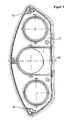
- FIG. 1 the rear view of a housing (10) of a left vehicle lamp is shown in the mounting position.
- a ventilation system (12) is formed, which is to prevent by the possibility of connecting the air in the interior of the vehicle lamp with the ambient air, the sowing of the lens, not shown.
- a drainage system (14) is formed, which makes it possible that unintentionally penetrated into the vehicle lamp dirt and / or spray water can flow out of this again.
- the drainage system (14) also serves as ventilation due to its construction. As can be easily seen from FIG.
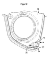
- the ventilation system (12) and the drainage system (14) are arranged and formed in mirror image to the horizontal central axis (16) of the vehicle lamp. This makes it possible to use the housing (10) for a right vehicle lamp, you just have to rotate the housing by 180 ° around the center of the central axis (16). Due to the mirror-image arrangement and design of the ventilation and drainage systems (12/14), only the design of the drainage system (14) is explained with reference to Figure 2, wherein Figure 2 shows an enlarged detail view of the lower third of the vehicle lamp shown in Figure 1.
- the at the lower outer region of the housing (10) arranged and trained drainage system (14) has a drainage opening (22) through which unintentionally penetrated dirt and / or spray can flow out of the vehicle light, on the other hand, but also an exchange of air take place inside the vehicle lamp and the environment can to prevent condensation of the lens, not shown.
- the drainage opening (22) is formed by the wall of a fastening dome (18) and a portion of the sealing web (20).
- the fastening dome (18) serves to allow the vehicle lamp to be fixed to the vehicle body by means of a screw, not shown.
- On the sealing web (20) a seal, not shown here, is placed, which is arranged between the vehicle lamp and the vehicle body.
Landscapes
- Engineering & Computer Science (AREA)
- General Engineering & Computer Science (AREA)
- Non-Portable Lighting Devices Or Systems Thereof (AREA)
- Arrangement Of Elements, Cooling, Sealing, Or The Like Of Lighting Devices (AREA)
- Glass Compositions (AREA)
- Inorganic Insulating Materials (AREA)
Abstract
Description
- Die Erfindung betrifft eine Fahrzeugleuchte mit einem Gehäuse, in welchem zumindest ein Beleuchtungselement angeordnet ist, mit einer das Gehäuse abdeckenden Lichtscheibe, mit einem Dichtungselement, welches zwischen der Fahrzeugkarosserie und dem Gehäuse angeordnet ist, mit Elementen zum Festsetzen der Fahrzeugleuchte an der Fahrzeugkarosserie und mit zumindest zwei Belüftungs- und/oder Entwässerungssystemen.
- Aus der
DE 199 44 288 A1 eine derartige Fahrzeugleuchte bekannt. Die bekannte Fahrzeugleuchte weist an ihrer zur Karosserie gewandten Gehäuseseite drei Belüftungssysteme auf, die durch die Verbindung der Luft im Leuchteninneren mit der Außenluft ein Betauen der Lichtscheibe insbesondere bei tieferen Temperaturen verhindern sollen. Es sind drei Belüftungssysteme angeordnet, um eine Zirkulation der Luft im Leuchteninneren zu ermöglichen, wobei ein Belüftungssystem oberhalb zumindest einer Lichtquelle angeordnet ist und zwei Belüftungssystems in einem unteren Bereich der Fahrzeugleuchte angeordnet sind. Um die Fahrzeugleuchte gegen das Eindringen von Schmutz- und/oder Spritzwasser zu schützen, sind die drei Belüftungsöffnungen mit unterschiedlich gestalteten, einstückig mit dem Gehäuse ausgebildeten Deckeln abgedeckt. Nachteilig an einer derart bekannten Fahrzeugleuchte ist es, dass aufgrund der nahezu willkürlichen Anordnung der Belüftungsöffnungen für die rechte und linke Leuchte eines Fahrzeuges unterschiedliche Gehäuse hergestellt werden müssen, was erhebliche Kosten bei der Entwicklung, Werkzeugerstellung, Herstellung, Lagerung und Montage der Leuchtengehäuse verursacht, da immer zwischen sogenannten rechten und linken Gehäusen unterschieden werden muss. Weiterhin ist es nachteilig, dass die bekannte Fahrzeugleuchte zwar eine Mehrzahl von Belüftungsöffnungen aufweist, jedoch keine Maßnahmen getroffen wurden für den Fall, dass doch einmal Schmutz- oder Spritzwasser in die Fahrzeugleuchte eindringt. so dass dieses dann aufgrund der Anordnung und Ausbildung der Belüftungsöffnungen in Fahrzeugleuchte verbleibt. - Es ist Aufgabe der vorliegenden Erfindung, eine Fahrzeugleuchte gemäß dem Oberbegriff des Anspruchs 1 derart auszubilden, dass sie zumindest zwei Belüftungs- und/oder Entwässerungssysteme aufweist und das Gehäuse für eine rechte und eine linke Fahrzeugleuchte identisch ausgebildet ist.
- Die Aufgabe wird in Verbindung mit den Merkmalen des Oberbegriffs des Anspruchs 1 dadurch gelöst, dass die zumindest zwei Belüftungs- und/oder Entwässerungssysteme spiegelbildlich zu einer Mittelachse der Fahrzeugleuchte angeordnet und ausgebildet sind. Eine derartige Anordnung der Belüftungs- und/oder Entwässerungssysteme ermöglicht es, dass durch einfache Drehung des Gehäuses um 180° um den Mittelpunkt der Mittelachse für rechte und linke Fahrzeugleuchten ein identisches Gehäuse Verwendung findet. Somit ist nur ein Gehäuse zu entwickeln, es wird nur ein Gehäusewerkzeug benötigt, beim Zwischenlagern und bei der Montage der Gehäuse braucht nicht zwischen den einzelnen Fahrzeugseiten unterscheiden zu werden. All diese Punkte tragen dazu bei, dass die Entwicklungs- und Herstellkosten einer erfindungsgemäßen Fahrzeugleuchte erheblich gegenüber einer aus dem Stand der Technik bekannten Fahrzeugleuchte vermindert werden.
- Eine Ausführungsform der Erfindung zeichnet sich dadurch aus, dass die zumindest zwei Belüftungs- und/oder Entwässerungssystems spiegelbildlich zu der horizontalen Mittelachse angeordnet und ausgebildet sind, wobei ein Belüftungs- und/oder Entwässerungssystem an einem in Anbaulage der Fahrzeugleuchte gesehen oberen randseitigen Bereich des Gehäuses ausgebildet ist und wobei ein Belüftungs- und/oder Entwässerungssystem an einem in Anbaulage der Fahrzeugleuchte gesehen unteren randseitigen Bereich des Gehäuses ausgebildet ist. Eine zweite Ausführungsform der Erfindung zeichnet sich dadurch aus, dass die zumindest zwei Belüftungs- und/oder Entwässerungssystems spiegelbildlich zu der vertikalen Mittelachse angeordnet und ausgebildet sind, wobei ein Belüftungs- und/oder Entwässerungssystem an einem in Anbaulage der Fahrzeugleuchte gesehen rechten randseitigen Bereich des Gehäuses ausgebildet ist und wobei ein Belüftungs- und/oder Entwässerungssystem an einem in Anbaulage der Fahrzeugleuchte gesehen linken randseitigen Bereich des Gehäuses ausgebildet ist.
Eine dritte Ausführungsform der Erfindung zeichnet sich schließlich dadurch aus, dass die zumindest zwei Belüftungs- und/oder Entwässerungssystems spiegelbildlich zu der diagonalen Mittelachse angeordnet und ausgebildet sind, wobei ein Belüftungs- und/oder Entwässerungssystem an einem in Anbaulage der Fahrzeugleuchte gesehen oberen rechten oder oberen linken randseitigen Bereich des Gehäuses ausgebildet ist und wobei ein Belüftungs- und/oder Entwässerungssystem an einem in Anbaulage der Fahrzeugleuchte gesehen unteren linken oder unteren rechten randseitigen Bereich des Gehäuses ausgebildet ist.
Durch eine Ausbildung der Fahrzeugleuchte gemäß der erstgenannten und/oder der drittgenannten Ausführungsform wird insbesondere ein sogenannter Kamineffekt erzeugt, bei dem Umgebungsluft durch das untere Belüftungs- und/oder Entwässerungssystem in die Fahrzeugleuchte eindringt und durch das obere Belüftungs- und/oder Entwässerungssystem wieder austritt, wobei Aerosole und Schmutzpartikelchen durch den Luftstrom mit aus der Fahrzeugleuchte befördert werden, was insbesondere ein Betauen und Verschmutzen verhindert. - Bei einer vorteilhaften Ausführungsform der Erfindung ist zumindest ein Wandungsbereich des Belüftungs- und/oder Entwässerungssystems durch die Wandung eines einstückig mit dem Gehäuses ausgebildeten Befestigungsdom gebildet, was den Vorteil bietet, dass Material für das Gehäuse eingespart wird, da benötigte Bereiche des Gehäuses für zwei Funktionen Verwendung finden.
- Bei einer vorteilhaften Ausgestaltung der Erfindung ist zumindest ein Wandungsbereich des Belüftungs- und/oder Entwässerungssystems durch die Wandung eines einstückig mit dem Gehäuse ausgebildeten Steg gebildet, was ebenfalls den Vorteil bietet, dass Material für das Gehäuse eingespart wird, da benötigte Bereiche des Gehäuses für zwei Funktionen Verwendung finden. Der Steg ist insbesondere als Dichtungssteg ausgebildet, der in Verbindung mit einem Dichtungselement zur Abdichtung zwischen Fahrzeugleuchte und Fahrzeugkarosserie dient.
- Bei einer vorteilhaften Ausführungsform der Erfindung laufen die die Belüftungs- und/oder Entwässerungssysteme bildenden Wandungsbereiche des Gehäuses in Anbaulage gesehen jeweils annähernd trichterförmig zum randseitigen Bereich des Gehäuses zu und die Belüftungs- und/oder Entwässerungsöffnungen sind jeweils durch, im Verhältnis zum Gesamtvolumen der Fahrzeugleuchte, kleine Öffnungen gebildet. Durch die kleinen Öffnungen wird gewährleistet, dass nur eine minimal Gefahr besteht, dass Schmutz- und/oder Spritzwasser in die Fahrzeugleuchte eindringen kann und trotzdem ein genügender Luftaustausch stattfinden kann. Durch die trichterförmige Ausbildung der Wandung wird es ermöglicht, dass evtl. doch in die Fahrzeugleuchte eingedrungenes Schmutz- und/oder Spritzwasser automatisch zu der an der tiefsten Stelle der Fahrzeugleuchte angeordnete Entwässerungsöffnung fließt und durch diese aus der Fahrzeugleuchte austreten kann.
- Um die Belüftungs- und/oder Entwässerungsöffnungen der Belüftungs- und/oder Entwässerungssysteme noch wirkungsvoller gegen das Eindringen von Schmutz- und/oder Spritzwasser zu schützen, ist bei einer vorteilhaften Ausführungsform der Erfindung den Belüftungs- und/oder Entwässerungsöffnungen jeweils eine einstückig mit dem Gehäuse ausgebildete Spritzschutzwand zugeordnet, wodurch eine Art Labyrinth gebildet wird.
- Eine vorteilhafte Ausgestaltung der Erfindung ist den Figuren zu entnehmen. Es zeigen
- Figur 1: eine rückwärtige Ansicht einer Fahrzeugleuchte und
- Figur 2: eine vergrößerte Detailansicht des unteren Drittels der in Figur 1 gezeigten Fahrzeugleuchte.
- In Figur 1 ist die rückwärtige Ansicht eines Gehäuses (10) einer linken Fahrzeugleuchte in Anbaulage gezeigt. In drei vertikal untereinander angeordneten kreisrunden Öffnungen sind hier nicht dargestellte Beleuchtungselemente angeordnet. Am oberen äußeren Bereich des Gehäuses (10) ist ein Belüftungssystem (12) ausgebildet, welches durch die Möglichkeit der Verbindung der Luft im Inneren der Fahrzeugleuchte mit der Umgebungsluft das Betauen der nicht dargestellten Lichtscheibe verhindern soll. Am unteren äußeren Bereich des Gehäuses (10) ist ein Entwässerungssystem (14) ausgebildet, welches es ermöglicht, dass ungewollt in die Fahrzeugleuchte eingedrungenes Schmutz- und/oder Spritzwasser wieder aus dieser herausfließen kann. Weiterhin dient das Entwässerungssystem (14) aufgrund seines Aufbaus ebenfalls als Belüftung. Wie Figur 1 leicht zu entnehmen ist, sind das Belüftungssystem (12) und das Entwässerungssystem (14) spiegelbildlich zu der horizontalen Mittelachse (16) der Fahrzeugleuchte angeordnet und ausgebildet. Dadurch ist es möglich, das Gehäuse (10) auch für eine rechte Fahrzeugleuchte zu nutzen, man muss lediglich das Gehäuse um 180° um den Mittelpunkt der Mittelachse (16) drehen. Aufgrund der spiegelbildlichen Anordnung und Ausbildung der Belüftungs- und Entwässerungssysteme (12/14) wird anhand Figur 2 nur die Ausbildung des Entwässerungssystems (14) erläutert, wobei Figur 2 eine vergrößerte Detailansicht des unteren Drittels der in Figur 1 gezeigten Fahrzeugleuchte zeigt. Das am unteren äußeren Bereich des Gehäuses (10) angeordnete und ausgebildete Entwässerungssystem (14) weist eine Entwässerungsöffnung (22) auf, durch die zum Einen ungewollt eingedrungenes Schmutz- und/oder Spritzwasser aus der Fahrzeugleuchte abfließen kann, zum Anderen aber auch ein Luftaustausch zwischen dem Inneren der Fahrzeugleuchte und der Umgebung stattfinden kann, um eine Betauung der nicht dargestellten Lichtscheibe zu verhindern. Die Entwässerungsöffnung (22) wird gebildet durch die Wandung eines Befestigungsdomes (18) und einem Teilbereich des Dichtungssteges (20). Der Befestigungsdom (18) dient dazu, dass die Fahrzeugleuchte mittels einer nicht dargestellten Schraube an der Fahrzeugkarosserie festgesetzt werden kann. Auf dem Dichtungssteg (20) ist eine hier nicht dargestellte Dichtung aufgesetzt, die zwischen der Fahrzeugleuchte und der Fahrzeugkarosserie angeordnet ist. Um zu Verhindern, dass Spritzwasser, beispielsweise durch die Fahrzeugreinigung mittels eines Hochdruckreinigers, durch die Entwässerungsöffnung (22) in die Fahrzeugleuchte eindringt, ist vor der Entwässerungsöffnung (22) eine einstückig mit dem Gehäuse (10) ausgebildete Spritzschutzwand (24) angeordnet, von der das Spritzwasser zurückgehalten wird.
-
- 10
- Gehäuse
- 12
- Belüftungssystem
- 14
- Entwässerungssystem
- 16
- Mittelachse
- 18
- Befestigungsdom
- 20
- Dichtungssteg
- 22
- Entwässerungsöffnung
- 24
- Spritzschutzwand
Claims (9)
- Fahrzeugleuchte mit einem Gehäuse (10), in welchem zumindest ein Beleuchtungselement angeordnet ist, mit einer das Gehäuse (10) abdeckenden Lichtscheibe, mit einem Dichtungselement, welches zwischen der Fahrzeugkarosserie und dem Gehäuse (10) angeordnet ist, mit Elementen zum Festsetzen der Fahrzeugleuchte an der Fahrzeugkarosserie und mit zumindest zwei Belüftungs- und/oder Entwässerungssystemen (12/14), dadurch gekennzeichnet, dass die zumindest zwei Belüftungs- und/oder Entwässerungssysteme (12/14) spiegelbildlich zu einer Mittelachse (16) der Fahrzeugleuchte angeordnet und ausgebildet sind.
- Fahrzeugleuchte nach Anspruch1, dadurch gekennzeichnet, dass die zumindest zwei Belüftungs- und/oder Entwässerungssysteme (12/14) spiegelbildlich zu der horizontalen Mittelachse (16) angeordnet und ausgebildet sind, wobei ein Belüftungs- und/oder Entwässerungssystem (12) an einem in Anbaulage der Fahrzeugleuchte gesehen oberen randseitigen Bereich des Gehäuses (10) ausgebildet ist und wobei ein Belüftungs- und/oder Entwässerungssystem (14) an einem in Anbaulage der Fahrzeugleuchte gesehen unteren randseitigen Bereich des Gehäuses (10) ausgebildet ist.
- Fahrzeugleuchte nach Anspruch1, dadurch gekennzeichnet, dass die zumindest zwei Belüftungs- und/oder Entwässerungssysteme (12/14) spiegelbildlich zu der vertikalen Mittelachse (16) angeordnet und ausgebildet sind, wobei ein Belüftungs- und/oder Entwässerungssystem (12) an einem in Anbaulage der Fahrzeugleuchte gesehen rechten randseitigen Bereich des Gehäuses (10) ausgebildet ist und wobei ein Belüftungs- und/oder Entwässerungssystem (14) an einem in Anbaulage der Fahrzeugleuchte gesehen linken randseitigen Bereich des Gehäuses (10) ausgebildet ist.
- Fahrzeugleuchte nach Anspruch1, dadurch gekennzeichnet, dass die zumindest zwei Belüftungs- und/oder Entwässerungssysteme (12/14) spiegelbildlich zu der diagonalen Mittelachse (16) angeordnet und ausgebildet sind, wobei ein Belüftungs- und/oder Entwässerungssystem (12) an einem in Anbaulage der Fahrzeugleuchte gesehen oberen rechten oder oberen linken randseitigen Bereich des Gehäuses (10) ausgebildet ist und wobei ein Belüftungs- und/oder Entwässerungssystem (14) an einem in Anbaulage der Fahrzeugleuchte gesehen unteren linken oder unteren rechten randseitigen Bereich des Gehäuses (10) ausgebildet ist.
- Fahrzeugleuchte nach einem der vorstehenden Ansprüche, dadurch gekennzeichnet, dass zumindest ein Wandungsbereich des Belüftungs- und/oder Entwässerungssystems (12/14) durch die Wandung eines einstückig mit dem Gehäuse (10) ausgebildeten Befestigungsdom (18) gebildet ist.
- Fahrzeugleuchte nach einem der vorstehenden Ansprüche, dadurch gekennzeichnet, dass zumindest ein Wandungsbereich des Belüftungs- und/oder Bewässerungssystems (12/14) durch die Wandung eines einstückig mit dem Gehäuse (10) ausgebildeten Steges gebildet ist.
- Fahrzeugleuchte nach Anspruch 6, dadurch gekennzeichnet, dass der Steg ein einstückig mit dem Gehäuse ausgebildeter Dichtungssteg (20) ist.
- Fahrzeugleuchte nach einem der vorstehenden Ansprüche, dadurch gekennzeichnet, dass die die Belüftungs- und/oder Entwässerungssysteme (12/14) bildenden Wandungsbereiche des Gehäuses (10) in Anbaulage gesehen jeweils annähernd trichterförmig zum randseitigen Bereich zulaufen und die Belüftungs- und/oder Entwässerungsöffnungen (22) jeweils durch, im Verhältnis zum Gesamtvolumen der Fahrzeugleuchte, kleine Öffnungen gebildet sind.
- Fahrzeugleuchte nach einem der vorstehenden Ansprüche, dadurch gekennzeichnet, dass den Belüftungs- und/oder Entwässerungsöffnungen (22) der Belüftungs- und/oder Entwässerungssysteme (12/14) jeweils eine einstückig mit dem Gehäuse (10) ausgebildete Spritzschutzwand (24) zugeordnet ist.
Applications Claiming Priority (1)
| Application Number | Priority Date | Filing Date | Title |
|---|---|---|---|
| DE102005025015A DE102005025015A1 (de) | 2005-05-30 | 2005-05-30 | Fahrzeugleuchte |
Publications (2)
| Publication Number | Publication Date |
|---|---|
| EP1729060A1 true EP1729060A1 (de) | 2006-12-06 |
| EP1729060B1 EP1729060B1 (de) | 2008-08-27 |
Family
ID=36754359
Family Applications (1)
| Application Number | Title | Priority Date | Filing Date |
|---|---|---|---|
| EP06114086A Expired - Lifetime EP1729060B1 (de) | 2005-05-30 | 2006-05-17 | Fahrzeugleuchte |
Country Status (3)
| Country | Link |
|---|---|
| EP (1) | EP1729060B1 (de) |
| AT (1) | ATE406544T1 (de) |
| DE (2) | DE102005025015A1 (de) |
Citations (4)
| Publication number | Priority date | Publication date | Assignee | Title |
|---|---|---|---|---|
| DE2610932A1 (de) * | 1976-03-16 | 1977-09-29 | Bosch Gmbh Robert | Scheinwerfer fuer kraftfahrzeuge |
| DE3424205A1 (de) * | 1984-06-30 | 1986-01-23 | Westfälische Metall Industrie KG Hueck & Co, 4780 Lippstadt | Fahrzeugleuchte |
| US4937710A (en) * | 1988-04-18 | 1990-06-26 | General Motors Corporation | Ventilation system for headlamp |
| DE19944288A1 (de) | 1998-09-18 | 2000-03-23 | Koito Mfg Co Ltd | Fahrzeugleuchte |
Family Cites Families (7)
| Publication number | Priority date | Publication date | Assignee | Title |
|---|---|---|---|---|
| DE3300383C2 (de) * | 1983-01-07 | 1987-02-19 | Hella KG Hueck & Co, 4780 Lippstadt | Fahrzeugleuchte |
| US5743631A (en) * | 1995-05-11 | 1998-04-28 | Bigham; James R. | Light bar heater |
| JP3122034B2 (ja) * | 1996-04-15 | 2001-01-09 | 株式会社小糸製作所 | 車輌用前照灯 |
| DE19841727A1 (de) * | 1998-09-12 | 2000-03-16 | Volkswagen Ag | Scheinwerfer oder Leuchte |
| JP2000243129A (ja) * | 1999-02-22 | 2000-09-08 | Honda Motor Co Ltd | 車両用灯火装置 |
| DE10135849A1 (de) * | 2001-07-23 | 2003-02-06 | Bayerische Motoren Werke Ag | Scheinwerfer für ein Kraftfahrzeug |
| DE10139818A1 (de) * | 2001-08-14 | 2003-02-27 | Opel Adam Ag | Scheinwerfer für ein Kraftfahrzeug |
-
2005
- 2005-05-30 DE DE102005025015A patent/DE102005025015A1/de not_active Withdrawn
-
2006
- 2006-05-17 EP EP06114086A patent/EP1729060B1/de not_active Expired - Lifetime
- 2006-05-17 DE DE502006001423T patent/DE502006001423D1/de not_active Expired - Lifetime
- 2006-05-17 AT AT06114086T patent/ATE406544T1/de active
Patent Citations (4)
| Publication number | Priority date | Publication date | Assignee | Title |
|---|---|---|---|---|
| DE2610932A1 (de) * | 1976-03-16 | 1977-09-29 | Bosch Gmbh Robert | Scheinwerfer fuer kraftfahrzeuge |
| DE3424205A1 (de) * | 1984-06-30 | 1986-01-23 | Westfälische Metall Industrie KG Hueck & Co, 4780 Lippstadt | Fahrzeugleuchte |
| US4937710A (en) * | 1988-04-18 | 1990-06-26 | General Motors Corporation | Ventilation system for headlamp |
| DE19944288A1 (de) | 1998-09-18 | 2000-03-23 | Koito Mfg Co Ltd | Fahrzeugleuchte |
Also Published As
| Publication number | Publication date |
|---|---|
| ATE406544T1 (de) | 2008-09-15 |
| DE502006001423D1 (de) | 2008-10-09 |
| DE102005025015A1 (de) | 2006-12-07 |
| EP1729060B1 (de) | 2008-08-27 |
Similar Documents
| Publication | Publication Date | Title |
|---|---|---|
| EP3853069B1 (de) | Lichtleitender kühlergrill für ein kraftfahrzeug | |
| DE19515040C2 (de) | Bullaugentür für eine von vorn beschickbare Trommelwaschmaschine | |
| DE102010010927B4 (de) | Schalldämpfungsblende für Entlüftungsventil | |
| DE69304829T2 (de) | Scheinwerfer für Kraftfahrzeuge mit verbessertem Ventilations- und Kühlsystem | |
| WO2008077667A2 (de) | Druckausgleichselement für ein gehäuse und kraftfahrzeug-elektrokomponente mit einem solchen druckausgleichselement | |
| DE102007008019B4 (de) | Luftauslass | |
| DE202006009355U1 (de) | Filterlüfter mit einer Schnellbefestigungseinrichtung | |
| EP3283353B1 (de) | Windlaufabdeckungsanordnung für ein kraftfahrzeug | |
| DE102008003931A1 (de) | Abdeckung für einen Luftfilter, insbesondere für ein Kraftfahrzeug | |
| DE3336003A1 (de) | Entlueftungseinrichtung fuer kraftfahrzeuge | |
| DE102014112535A1 (de) | Kraftfahrzeugklimaanlage mit lösbar verbundenem Filterdeckel | |
| EP2088015B1 (de) | Deckel-Gehäuse-Anordnung, insbesondere für einen Filter eines Fahrzeug-Beluftungsysteme | |
| DE3604615A1 (de) | Leuchte | |
| DE112019001740T5 (de) | Geruchsverschluss | |
| DE102005045292A1 (de) | Entwässerungsanordnung für einen Hohlraum einer Kraftwagenkarosserie | |
| EP1729060B1 (de) | Fahrzeugleuchte | |
| DE19838950A1 (de) | Beleuchtungseinrichtung für Fahrzeuge | |
| DE3300383A1 (de) | Fahrzeugleuchte | |
| DE102007044422B4 (de) | Wasserablauftülle | |
| DE202007012195U1 (de) | Dachfenster für Freizeitmobile | |
| DE10055152B4 (de) | Belüftungssystem einer Leuchte, insbesondere eines Scheinwerfers für Fahrzeuge | |
| DE2017093A1 (de) | Anordnung mit einem Außenrückblickspiegel für Fahrzeuge, insbesondere Kraftfahrzeuge | |
| DE69406452T2 (de) | Lampenzusammenbau mit ventilationsdurchlass | |
| DE69321373T2 (de) | Scheinwerfer mit einer verbesserten Belüftungsvorrichtung, insbesondere für Kraftfahrzeuge | |
| DE19825705B4 (de) | Geräuschminimiertes Fahrzeug-Außenspiegelgehäuse |
Legal Events
| Date | Code | Title | Description |
|---|---|---|---|
| PUAI | Public reference made under article 153(3) epc to a published international application that has entered the european phase |
Free format text: ORIGINAL CODE: 0009012 |
|
| AK | Designated contracting states |
Kind code of ref document: A1 Designated state(s): AT BE BG CH CY CZ DE DK EE ES FI FR GB GR HU IE IS IT LI LT LU LV MC NL PL PT RO SE SI SK TR |
|
| AX | Request for extension of the european patent |
Extension state: AL BA HR MK YU |
|
| 17P | Request for examination filed |
Effective date: 20070530 |
|
| 17Q | First examination report despatched |
Effective date: 20070704 |
|
| AKX | Designation fees paid |
Designated state(s): AT BE BG CH CY CZ DE DK EE ES FI FR GB GR HU IE IS IT LI LT LU LV MC NL PL PT RO SE SI SK TR |
|
| GRAP | Despatch of communication of intention to grant a patent |
Free format text: ORIGINAL CODE: EPIDOSNIGR1 |
|
| GRAS | Grant fee paid |
Free format text: ORIGINAL CODE: EPIDOSNIGR3 |
|
| GRAA | (expected) grant |
Free format text: ORIGINAL CODE: 0009210 |
|
| AK | Designated contracting states |
Kind code of ref document: B1 Designated state(s): AT BE BG CH CY CZ DE DK EE ES FI FR GB GR HU IE IS IT LI LT LU LV MC NL PL PT RO SE SI SK TR |
|
| REG | Reference to a national code |
Ref country code: GB Ref legal event code: FG4D Free format text: NOT ENGLISH |
|
| REG | Reference to a national code |
Ref country code: CH Ref legal event code: EP |
|
| REG | Reference to a national code |
Ref country code: IE Ref legal event code: FG4D Free format text: LANGUAGE OF EP DOCUMENT: GERMAN |
|
| REF | Corresponds to: |
Ref document number: 502006001423 Country of ref document: DE Date of ref document: 20081009 Kind code of ref document: P |
|
| PG25 | Lapsed in a contracting state [announced via postgrant information from national office to epo] |
Ref country code: IS Free format text: LAPSE BECAUSE OF FAILURE TO SUBMIT A TRANSLATION OF THE DESCRIPTION OR TO PAY THE FEE WITHIN THE PRESCRIBED TIME-LIMIT Effective date: 20081227 Ref country code: LT Free format text: LAPSE BECAUSE OF FAILURE TO SUBMIT A TRANSLATION OF THE DESCRIPTION OR TO PAY THE FEE WITHIN THE PRESCRIBED TIME-LIMIT Effective date: 20080827 Ref country code: NL Free format text: LAPSE BECAUSE OF FAILURE TO SUBMIT A TRANSLATION OF THE DESCRIPTION OR TO PAY THE FEE WITHIN THE PRESCRIBED TIME-LIMIT Effective date: 20080827 |
|
| PG25 | Lapsed in a contracting state [announced via postgrant information from national office to epo] |
Ref country code: LV Free format text: LAPSE BECAUSE OF FAILURE TO SUBMIT A TRANSLATION OF THE DESCRIPTION OR TO PAY THE FEE WITHIN THE PRESCRIBED TIME-LIMIT Effective date: 20080827 Ref country code: ES Free format text: LAPSE BECAUSE OF FAILURE TO SUBMIT A TRANSLATION OF THE DESCRIPTION OR TO PAY THE FEE WITHIN THE PRESCRIBED TIME-LIMIT Effective date: 20081208 Ref country code: FI Free format text: LAPSE BECAUSE OF FAILURE TO SUBMIT A TRANSLATION OF THE DESCRIPTION OR TO PAY THE FEE WITHIN THE PRESCRIBED TIME-LIMIT Effective date: 20080827 Ref country code: SI Free format text: LAPSE BECAUSE OF FAILURE TO SUBMIT A TRANSLATION OF THE DESCRIPTION OR TO PAY THE FEE WITHIN THE PRESCRIBED TIME-LIMIT Effective date: 20080827 |
|
| REG | Reference to a national code |
Ref country code: IE Ref legal event code: FD4D |
|
| PG25 | Lapsed in a contracting state [announced via postgrant information from national office to epo] |
Ref country code: IE Free format text: LAPSE BECAUSE OF FAILURE TO SUBMIT A TRANSLATION OF THE DESCRIPTION OR TO PAY THE FEE WITHIN THE PRESCRIBED TIME-LIMIT Effective date: 20080827 Ref country code: DK Free format text: LAPSE BECAUSE OF FAILURE TO SUBMIT A TRANSLATION OF THE DESCRIPTION OR TO PAY THE FEE WITHIN THE PRESCRIBED TIME-LIMIT Effective date: 20080827 Ref country code: BG Free format text: LAPSE BECAUSE OF FAILURE TO SUBMIT A TRANSLATION OF THE DESCRIPTION OR TO PAY THE FEE WITHIN THE PRESCRIBED TIME-LIMIT Effective date: 20081127 |
|
| PG25 | Lapsed in a contracting state [announced via postgrant information from national office to epo] |
Ref country code: CZ Free format text: LAPSE BECAUSE OF FAILURE TO SUBMIT A TRANSLATION OF THE DESCRIPTION OR TO PAY THE FEE WITHIN THE PRESCRIBED TIME-LIMIT Effective date: 20080827 Ref country code: PT Free format text: LAPSE BECAUSE OF FAILURE TO SUBMIT A TRANSLATION OF THE DESCRIPTION OR TO PAY THE FEE WITHIN THE PRESCRIBED TIME-LIMIT Effective date: 20090127 Ref country code: SK Free format text: LAPSE BECAUSE OF FAILURE TO SUBMIT A TRANSLATION OF THE DESCRIPTION OR TO PAY THE FEE WITHIN THE PRESCRIBED TIME-LIMIT Effective date: 20080827 Ref country code: RO Free format text: LAPSE BECAUSE OF FAILURE TO SUBMIT A TRANSLATION OF THE DESCRIPTION OR TO PAY THE FEE WITHIN THE PRESCRIBED TIME-LIMIT Effective date: 20080827 |
|
| PLBE | No opposition filed within time limit |
Free format text: ORIGINAL CODE: 0009261 |
|
| STAA | Information on the status of an ep patent application or granted ep patent |
Free format text: STATUS: NO OPPOSITION FILED WITHIN TIME LIMIT |
|
| PG25 | Lapsed in a contracting state [announced via postgrant information from national office to epo] |
Ref country code: EE Free format text: LAPSE BECAUSE OF FAILURE TO SUBMIT A TRANSLATION OF THE DESCRIPTION OR TO PAY THE FEE WITHIN THE PRESCRIBED TIME-LIMIT Effective date: 20080827 |
|
| 26N | No opposition filed |
Effective date: 20090528 |
|
| PG25 | Lapsed in a contracting state [announced via postgrant information from national office to epo] |
Ref country code: IT Free format text: LAPSE BECAUSE OF FAILURE TO SUBMIT A TRANSLATION OF THE DESCRIPTION OR TO PAY THE FEE WITHIN THE PRESCRIBED TIME-LIMIT Effective date: 20080827 |
|
| BERE | Be: lapsed |
Owner name: HELLA KGAA HUECK & CO. Effective date: 20090531 |
|
| PG25 | Lapsed in a contracting state [announced via postgrant information from national office to epo] |
Ref country code: MC Free format text: LAPSE BECAUSE OF NON-PAYMENT OF DUE FEES Effective date: 20090531 |
|
| PG25 | Lapsed in a contracting state [announced via postgrant information from national office to epo] |
Ref country code: SE Free format text: LAPSE BECAUSE OF FAILURE TO SUBMIT A TRANSLATION OF THE DESCRIPTION OR TO PAY THE FEE WITHIN THE PRESCRIBED TIME-LIMIT Effective date: 20081127 |
|
| PG25 | Lapsed in a contracting state [announced via postgrant information from national office to epo] |
Ref country code: PL Free format text: LAPSE BECAUSE OF FAILURE TO SUBMIT A TRANSLATION OF THE DESCRIPTION OR TO PAY THE FEE WITHIN THE PRESCRIBED TIME-LIMIT Effective date: 20080827 |
|
| PG25 | Lapsed in a contracting state [announced via postgrant information from national office to epo] |
Ref country code: BE Free format text: LAPSE BECAUSE OF NON-PAYMENT OF DUE FEES Effective date: 20090531 |
|
| PG25 | Lapsed in a contracting state [announced via postgrant information from national office to epo] |
Ref country code: GR Free format text: LAPSE BECAUSE OF FAILURE TO SUBMIT A TRANSLATION OF THE DESCRIPTION OR TO PAY THE FEE WITHIN THE PRESCRIBED TIME-LIMIT Effective date: 20081128 |
|
| REG | Reference to a national code |
Ref country code: CH Ref legal event code: PL |
|
| PG25 | Lapsed in a contracting state [announced via postgrant information from national office to epo] |
Ref country code: CH Free format text: LAPSE BECAUSE OF NON-PAYMENT OF DUE FEES Effective date: 20100531 Ref country code: LI Free format text: LAPSE BECAUSE OF NON-PAYMENT OF DUE FEES Effective date: 20100531 |
|
| PG25 | Lapsed in a contracting state [announced via postgrant information from national office to epo] |
Ref country code: LU Free format text: LAPSE BECAUSE OF NON-PAYMENT OF DUE FEES Effective date: 20090517 |
|
| PG25 | Lapsed in a contracting state [announced via postgrant information from national office to epo] |
Ref country code: HU Free format text: LAPSE BECAUSE OF FAILURE TO SUBMIT A TRANSLATION OF THE DESCRIPTION OR TO PAY THE FEE WITHIN THE PRESCRIBED TIME-LIMIT Effective date: 20090228 |
|
| PG25 | Lapsed in a contracting state [announced via postgrant information from national office to epo] |
Ref country code: TR Free format text: LAPSE BECAUSE OF FAILURE TO SUBMIT A TRANSLATION OF THE DESCRIPTION OR TO PAY THE FEE WITHIN THE PRESCRIBED TIME-LIMIT Effective date: 20080827 |
|
| PG25 | Lapsed in a contracting state [announced via postgrant information from national office to epo] |
Ref country code: CY Free format text: LAPSE BECAUSE OF FAILURE TO SUBMIT A TRANSLATION OF THE DESCRIPTION OR TO PAY THE FEE WITHIN THE PRESCRIBED TIME-LIMIT Effective date: 20080827 |
|
| PGFP | Annual fee paid to national office [announced via postgrant information from national office to epo] |
Ref country code: AT Payment date: 20120426 Year of fee payment: 7 |
|
| PGFP | Annual fee paid to national office [announced via postgrant information from national office to epo] |
Ref country code: DE Payment date: 20130515 Year of fee payment: 8 Ref country code: GB Payment date: 20130515 Year of fee payment: 8 |
|
| PGFP | Annual fee paid to national office [announced via postgrant information from national office to epo] |
Ref country code: FR Payment date: 20130531 Year of fee payment: 8 |
|
| REG | Reference to a national code |
Ref country code: DE Ref legal event code: R119 Ref document number: 502006001423 Country of ref document: DE |
|
| REG | Reference to a national code |
Ref country code: AT Ref legal event code: MM01 Ref document number: 406544 Country of ref document: AT Kind code of ref document: T Effective date: 20140517 |
|
| GBPC | Gb: european patent ceased through non-payment of renewal fee |
Effective date: 20140517 |
|
| REG | Reference to a national code |
Ref country code: DE Ref legal event code: R119 Ref document number: 502006001423 Country of ref document: DE Effective date: 20141202 |
|
| PG25 | Lapsed in a contracting state [announced via postgrant information from national office to epo] |
Ref country code: AT Free format text: LAPSE BECAUSE OF NON-PAYMENT OF DUE FEES Effective date: 20140517 |
|
| REG | Reference to a national code |
Ref country code: FR Ref legal event code: ST Effective date: 20150130 |
|
| PG25 | Lapsed in a contracting state [announced via postgrant information from national office to epo] |
Ref country code: DE Free format text: LAPSE BECAUSE OF NON-PAYMENT OF DUE FEES Effective date: 20141202 |
|
| PG25 | Lapsed in a contracting state [announced via postgrant information from national office to epo] |
Ref country code: GB Free format text: LAPSE BECAUSE OF NON-PAYMENT OF DUE FEES Effective date: 20140517 Ref country code: FR Free format text: LAPSE BECAUSE OF NON-PAYMENT OF DUE FEES Effective date: 20140602 |