EP1728993A2 - Ventilzeitensteuerung - Google Patents
Ventilzeitensteuerung Download PDFInfo
- Publication number
- EP1728993A2 EP1728993A2 EP06252793A EP06252793A EP1728993A2 EP 1728993 A2 EP1728993 A2 EP 1728993A2 EP 06252793 A EP06252793 A EP 06252793A EP 06252793 A EP06252793 A EP 06252793A EP 1728993 A2 EP1728993 A2 EP 1728993A2
- Authority
- EP
- European Patent Office
- Prior art keywords
- internal combustion
- combustion engine
- overlap
- driving
- timing
- Prior art date
- Legal status (The legal status is an assumption and is not a legal conclusion. Google has not performed a legal analysis and makes no representation as to the accuracy of the status listed.)
- Withdrawn
Links
- 238000002485 combustion reaction Methods 0.000 claims abstract description 48
- 239000000498 cooling water Substances 0.000 claims description 68
- 238000000034 method Methods 0.000 claims description 26
- 238000005259 measurement Methods 0.000 claims description 5
- 230000007246 mechanism Effects 0.000 abstract description 14
- 239000000446 fuel Substances 0.000 description 39
- 230000008569 process Effects 0.000 description 17
- 229930195733 hydrocarbon Natural products 0.000 description 15
- 150000002430 hydrocarbons Chemical class 0.000 description 15
- 239000004215 Carbon black (E152) Substances 0.000 description 11
- 239000003054 catalyst Substances 0.000 description 10
- 238000010792 warming Methods 0.000 description 10
- 230000007423 decrease Effects 0.000 description 7
- 230000003247 decreasing effect Effects 0.000 description 7
- 238000001704 evaporation Methods 0.000 description 6
- 230000008020 evaporation Effects 0.000 description 6
- 238000002347 injection Methods 0.000 description 6
- 239000007924 injection Substances 0.000 description 6
- 230000004044 response Effects 0.000 description 6
- XLYOFNOQVPJJNP-UHFFFAOYSA-N water Substances O XLYOFNOQVPJJNP-UHFFFAOYSA-N 0.000 description 5
- 208000021017 Weight Gain Diseases 0.000 description 4
- 238000010586 diagram Methods 0.000 description 4
- 230000004584 weight gain Effects 0.000 description 4
- 235000019786 weight gain Nutrition 0.000 description 4
- 230000001737 promoting effect Effects 0.000 description 3
- 238000006243 chemical reaction Methods 0.000 description 2
- 230000001934 delay Effects 0.000 description 2
- 230000000694 effects Effects 0.000 description 2
- 230000009467 reduction Effects 0.000 description 2
- 238000009834 vaporization Methods 0.000 description 2
- 230000008016 vaporization Effects 0.000 description 2
- 230000003213 activating effect Effects 0.000 description 1
- 230000004913 activation Effects 0.000 description 1
- 230000003197 catalytic effect Effects 0.000 description 1
- 230000008859 change Effects 0.000 description 1
- 230000003111 delayed effect Effects 0.000 description 1
- 239000010720 hydraulic oil Substances 0.000 description 1
- 239000000203 mixture Substances 0.000 description 1
- 238000012986 modification Methods 0.000 description 1
- 230000004048 modification Effects 0.000 description 1
- 230000000979 retarding effect Effects 0.000 description 1
Images




Classifications
-
- F—MECHANICAL ENGINEERING; LIGHTING; HEATING; WEAPONS; BLASTING
- F02—COMBUSTION ENGINES; HOT-GAS OR COMBUSTION-PRODUCT ENGINE PLANTS
- F02D—CONTROLLING COMBUSTION ENGINES
- F02D13/00—Controlling the engine output power by varying inlet or exhaust valve operating characteristics, e.g. timing
- F02D13/02—Controlling the engine output power by varying inlet or exhaust valve operating characteristics, e.g. timing during engine operation
-
- Y—GENERAL TAGGING OF NEW TECHNOLOGICAL DEVELOPMENTS; GENERAL TAGGING OF CROSS-SECTIONAL TECHNOLOGIES SPANNING OVER SEVERAL SECTIONS OF THE IPC; TECHNICAL SUBJECTS COVERED BY FORMER USPC CROSS-REFERENCE ART COLLECTIONS [XRACs] AND DIGESTS
- Y02—TECHNOLOGIES OR APPLICATIONS FOR MITIGATION OR ADAPTATION AGAINST CLIMATE CHANGE
- Y02T—CLIMATE CHANGE MITIGATION TECHNOLOGIES RELATED TO TRANSPORTATION
- Y02T10/00—Road transport of goods or passengers
- Y02T10/10—Internal combustion engine [ICE] based vehicles
- Y02T10/12—Improving ICE efficiencies
Definitions
- the present invention relates to valve timing control and particularly, but not exclusively, to an apparatus and method for controlling valve timing in an internal combustion engine in order to control an overlap period during which an intake valve and an exhaust valve are open, thereby to improve exhaust performance during cold driving and/or starting.
- the invention also relates to a vehicle.
- Internal combustion engines generally include a catalytic converter formed of a three way catalyst or the like in some point of an exhaust channel to reduce hydrocarbons, etc., in exhaust gas.
- the catalyst converters cannot sufficiently purify the hydrocarbons, etc., until the catalyst converter reaches an activating temperature, so that the efficiency of purifying hydrocarbons, etc., is reduced during a cold start.
- Japanese Unexamined Patent Application Publication No. 7-109934 discloses a technique for improving exhaust performance during a cold start by increasing the overlap period during the cold start by using a valve-timing control mechanism capable of controlling the overlap period.
- control mechanism checks to determine whether the combustion engine is in the cold start mode from the water temperature and the driving state directly after the engine is started, wherein when the control mechanism determines that the engine is in the cold start mode, the control mechanism switches the overlap period to a preset overlap period for the cold start which is longer than that for normal driving.
- the overlap period during an engine start depends on whether the water temperature at the engine start is lower than a predetermined temperature, or whether the engine is in the cold start mode. Accordingly, the same overlap period is set for temperatures lower than the predetermined temperature irrespective of the cooling water temperature, so that an excessively long overlap period may be set to decrease burning performance.
- a valve-timing control apparatus of an internal combustion engine comprising a valve timing controller that continuously and variably controls an overlap period of an intake valve and an exhaust valve of an internal combustion engine, a driving-state determination means for determining the driving state of the internal combustion engine and an overlap-period setting means for setting the overlap period with the valve timing controller, wherein the overlap-period setting means sets the overlap period during a start of the internal combustion engine on the basis of the determinations of the driving-state determination means which vary as the internal combustion engine starts.
- the overlap-period setting means repeatedly updates the overlap period calculated using the determinations of the driving-state determination means as parameters at predetermined intervals after the internal combustion engine starts until warming up of the internal combustion engine is achieved.
- the driving-state determination means measures cooling-water temperature and determines the driving state in dependence thereon.
- the lower the cooling-water temperature the longer the overlap-period is set by the overlap-period setting means.
- the overlap-period setting means may decrease the overlap period as the cooling water temperature increases.
- the driving-state determination means measures the temperature of the intake valve and determines the driving state in dependence thereon.
- the lower the intake valve temperature the longer the overlap-period setting means sets the overlap period.
- the overlap-period setting means may decrease the overlap-period as the intake valve temperature increases.
- the apparatus may comprise ignition-timing setting means for setting the ignition timing of the internal combustion engine on the basis of the determination of the driving-state determination means.
- the ignition-timing setting means may set the ignition timing during a cold start of the internal combustion engine on the basis of the measurements of the driving-state determination means at the engine startup.
- the ignition-timing setting means repeatedly updates the setting of the ignition timing based on the measurements of the driving-state determination means at predetermined intervals until the warming up of the internal combustion engine is achieved.
- the apparatus may comprise means for measuring an actual overlap period.
- the ignition-timing setting means may set the ignition timing of the internal combustion engine on the basis of the actual overlap period.
- a valve-timing control apparatus of an internal combustion engine comprising a valve timing controller that continuously and variably controls an overlap period of an intake valve and an exhaust valve of an internal combustion engine, a driving-state determination mechanism for determining the driving state of the internal combustion engine and an overlap-period setting apparatus for setting the overlap period with the valve timing controller, wherein the overlap-period setting apparatus sets the overlap period during the start of the internal combustion engine on the basis of the determinations of the driving-state determination mechanism which vary as the internal combustion engine starts.
- a method for controlling valve timing of an internal combustion engine comprising determining the driving state of the internal combustion engine and continuously and variably setting an overlap period of an intake valve and an exhaust valve of the internal combustion engine on the basis of the determination of the driving state which varies as the internal combustion engine starts.
- one of cooling-water temperature and intake valve temperature is the driving state that is determined.
- Embodiments of the invention provide a valve timing controller capable of continuously and variably controlling the overlap period of an intake valve and an exhaust valve of an internal combustion engine.
- a driving-state determination mechanism determines the driving state of the internal combustion engine and an overlap-period setting apparatus sets the overlap period with the valve timing controller.
- the overlap-period setting apparatus sets the overlap period during the start of the internal combustion engine on the basis of the determinations of the driving-state determination mechanism which vary as the internal combustion engine starts.
- Fig. 1 is a schematic diagram of a system incorporating the embodiments.
- Reference numeral 1 denotes an engine
- numeral 2 denotes an intake channel connected to an intake port 4 of the engine
- numeral 3 indicates an exhaust channel connected to an exhaust port 5 of the engine 1.
- a piston 19 is slidably disposed in a cylinder 23 of the engine 1.
- the piston 19 connects to a crankshaft (not shown) via a connecting rod 20.
- An intake valve 10 and an exhaust valve 11 are provided at openings of the intake port 4 and the exhaust port 5 adjacent to the cylinder 23, respectively.
- the intake valve 10 and the exhaust valve 11 are opened and closed in association with sliding of the piston 19.
- the exhaust valve 11 is actuated by an exhaust camshaft 13 rotating with a crankshaft (not shown).
- the intake valve 10 is actuated by an intake camshaft (not shown) in a manner similar to the exhaust valve 11.
- the intake camshaft includes a valve-timing controller (hereinafter, referred to as a VTC) 12 for variably controlling the timing of opening and closing the intake valve 10, i.e., valve timing.
- VTC valve-timing controller
- the VTC 12 may control at least the open timing of the intake valve 10, and uses a mechanism similar to known mechanisms such as a method for varying the relationship between the timing of opening and closing the intake valve and the angle of the crankshaft by rotating a cam pulley (not shown) provided at the end of the intake camshaft (not shown) to route a timing chain or the like.
- a twist angle the rotation angle at which the cam pulley is rotated around the intake camshaft from the initial state of the VTC 12 is referred to as "a twist angle”.
- the twist angle is set large in the direction in which the open timing of the intake valve 10 is advanced, and set small in the direction in which the open timing is retarded. In other words, the twist angle is set large to increase the overlap period.
- a spark plug 21 for sparking the fuel air mixture in the cylinder 23 is opposed to a combustion chamber 24.
- the intake channel 2 has an air flow meter 8 for measuring the amount of intake air, a throttle valve 7 for controlling the amount of intake air, a collector tank 6 for distributing the intake air into the cylinders of the engine 1, and a fuel injection valve 14 for injecting fuel toward the intake port 4 in sequence from the upper stream.
- the throttle valve 7 of this embodiment is what is called a computerized throttle whose opening and closing are controlled electronically, the invention is not so limited.
- the exhaust channel 3 has an air-fuel ratio sensor 9 for measuring the air fuel ratio of exhaust gas and an exhaust-gas purifying catalyst 22 for purifying exhaust gas in sequence from an upper stream.
- the measurements of the air flow meter 8 and the air-fuel ratio sensor 9 are read by a control unit 15.
- the control unit 15 also reads signals sensed and measured by a water temperature sensor 18 for measuring the temperature of cooling water as a driving-state determination mechanism, an accelerator position sensor 16 for detecting the position of an accelerator, and a crank angle sensor 17 that measures the crank angle for measuring the RPM of the engine 1.
- the control unit 15 calculates a required intake air amount, a target air-fuel ratio, etc. from the signals to thereby control the opening of the throttle valve 7 and a fuel injection quantity, to control the timing of ignition as an ignition-timing setting apparatus, and to set an overlap period and control the valve timing, to be described later, as an overlap-period setting apparatus.
- FIG. 2 illustrates a routine for controlling valve timing and ignition timing performed by the control unit 15.
- the control routine will be described in the order of steps.
- step S101 the control unit 15 reads a cooling-water temperature TWINT at the starting of the engine 1 from the signal of the water temperature sensor 18.
- step S102 the control unit 15 checks to determine whether the detected cooling-water temperature TWINT is lower than a predetermined temperature K.
- step S111 When the cooling-water temperature TWINT is higher than the predetermined temperature K, the process proceeds to step S111.
- the process proceeds to step S103, where a target VTC position is set as the initial value of a VTC twist angle.
- the predetermined temperature K is a preset temperature for determining if the engine 1 is in a cold start mode.
- the target VTC position VTCTRG is a VTC twist angle for enabling the intake valve 10 to open at a target crankshaft angle which is set by map searching or the like in response to the starting cooling-water temperature TWINT.
- the initial VTC position VTCINT indicates the initial position of the VTC 12, or a state in which the twist angle is zero.
- a temperature almost equal to a temperature at which warming up end is set.
- step S104 the present cooling-water temperature TWN is read.
- step S105 the control unit 15 checks to determine whether the read cooling-water temperature TWN is higher than the starting cooling-water temperature TWINT, or whether the cooling water temperature is increasing. When the present cooling-water temperature TWN is higher, the process proceeds to step S106 and step S107; otherwise the process returns to step S104.
- step S106 a twist angle VTC is calculated. Specifically, as shown in Fig. 3, the relationship between cooling water temperatures and twist angles is mapped, which is searched for the cooling-water temperature TWN read in step S104.
- the map shows that the twist angle is large when the cooling-water temperature TWN is low, and decreases gradually with an increase in temperature beyond a predetermined temperature. This is for the following reasons.
- the temperatures of the wall surface of the intake port 4 and the intake valve 10 also increase, thus facilitating evaporation of fuel in the intake port 4.
- the overlap period is decreased gradually with an increase in cooling-water temperature.
- step S 107 the twist angle calculated in step S 106 is set as a target VTC position VTCTRG.
- step S108 ignition timing is calculated. Specifically, the relationship between cooling-water temperature TWN and ignition timing is mapped, as shown in Fig. 4, and ignition timing is found by searching the map.
- the map is set in such a manner that the lower the cooling-water temperature TWN, the more the ignition timing is advanced. This is for the following reasons.
- the ignition timing is advanced to thereby ensure burning stability; at high temperatures at which burning stability is high, the ignition timing is retarded gradually to thereby increase exhaust temperature, thus improving the efficiency of conversion of the exhaust-gas purifying catalyst 22.
- step S 109 the ignition timing calculated in step S108 is set as target ignition timing ADV.
- step S 110 After a target twist angle VTGTRG and target ignition timing ADV have been set in steps S107 and S109, the process proceeds to step S 110, wherein it is determined whether the cooling-water temperature TWN has reached a predetermined temperature K1.
- the predetermined temperature K1 is set to a temperature at which engine warming up is regarded as having been completed.
- step S104 When the cooling-water temperature TWN is lower than the predetermined temperature K1, the process returns to step S104, and the steps S104 to S109 are repeated.
- step S111 the control of the twist angle and the ignition timing is switched to a control mode for normal driving.
- a VTC twist angle for cold start and an ignition timing responsive to the VTC twist angle are set.
- the VTC twist angle is gradually decreased as the cooling-water temperature increases, with which the ignition timing is also retarded gradually.
- the exhaust temperature is increased by the retard of the ignition timing, so that the exhaust-gas purifying catalyst 22 can be activated early.
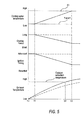
- Fig. 5 is a time chart for the cooling-water temperature, overlap period, ignition timing, and exhaust temperature.
- the solid lines graphically illustrate the control of the embodiment, while the broken lines graphically illustrate a control in which the overlap period and ignition timing set at engine starting are maintained until the end of warming up, as in the related art.
- the engine 1 is started at t0, and the initial value of the overlap period (VTC twist angle) is set on the basis of the cooling-water temperature TWINT at that time.
- VTC twist angle the initial value of the overlap period
- the temperature of the exhaust-gas purifying catalyst 22 rises faster than that by the control of the related art, so that the temperature of the exhaust-gas purifying catalyst 22 reaches an activation temperature at t2 before the end of the warming up.
- tail-pipe hydrocarbon emission can be reduced more than that by the control of the related art.
- This embodiment therefore offers the following advantages.
- the VTC 12 is capable of variably controlling the overlap period of the intake valve 10 and the exhaust valve 11 of the engine 1, the water temperature sensor 18 for measuring the cooling-water temperature of the engine 1, and the control unit 15 for setting the overlap period.
- the control unit 15 sets the overlap period at the start of the engine 1 on the basis of the cooling-water temperature at the start of the engine 1, so that an overlap period suitable for the condition of the engine 1 can be set. This prevents the overlap period from increasing unnecessarily to reduce burning performance while promoting the evaporation of fuel due to the backward flow of high-temperature burned gas into the intake port 4 at the end of the discharge stroke and reducing hydrocarbon emission due to the backward flow of the hydrocarbons generated at the end of the discharge stroke. As a result, the hydrocarbon emission at the start of the engine 1 can be reduced.
- the overlap period is set longer as the cooling-water temperature is lower, the backward flow of high-temperature burned gas increases as the temperatures of the wall surface of the intake port 4 and the intake valve 10 are lower, in which wall flow is likely to occur, thus promoting the evaporation of fuel.
- the overlap period during engine starting is set on the basis of the driving state at engine starting, e.g., the temperatures of the cooling water and the intake valve.
- FIG. 6 shows a control routine of this embodiment, which is different from that of the first embodiment in that the change of the ignition timing is set on the basis of an actual VTC twist angle (which is measured by a sensor).
- the control routine will be described in the order of steps.
- step S201 engine RPM N, accelerator position APO, cooling-water temperature TWN, and VTC twist angle VTCN (which is measured by a sensor) are read.
- step S202 it is determined whether the engine 1 is cranking. When it is determined that the engine 1 is cranking, the process proceeds to step S203; when it is not, the process proceeds to step S206.
- step S203 the cooling-water temperature TWN read in step S201 is set as a starting cooling-water temperature TWINT.
- step S204 the VTC twist angle for starting the engine 1 is controlled. Specifically, a target VTC twist angle is set to the initial state of the VTC 12, for example, a minimum retard angle VTCmin.
- step S205 the ignition timing for starting is controlled. Specifically, ignition timing ADV suitable for starting the engine 1 is calculated from the engine RPM N and the cooling-water temperature TWN.
- step S206 When it is determined in step S202 that the engine 1 is not cranking, or is autonomously rotating, it is determined in step S206 whether the accelerator position APO is at zero. When the accelerator position is at approximately zero, the process proceeds to step S207; when it is not approximately zero, the process proceeds to step S212.
- the determination may be made on the basis of the condition of the idle switch.
- step S207 it is determined whether the starting cooling-water temperature TWINT is lower than the predetermined temperature K.
- the predetermined temperature K is a temperature for determining whether the engine 1 is in cold start mode, as in the first embodiment.
- the predetermined temperature K is set in advance.
- step S208 When the starting cooling-water temperature TWINT is lower than the predetermined temperature K, the process proceeds to step S208. When it is not, the process proceeds to step S212.
- step S208 it is determined whether the cooling-water temperature TWN read in step S201 is lower than a predetermined temperature K1.
- the predetermined temperature K1 is set to a temperature close to the predetermined temperature K and higher than the predetermined temperature K.
- the process moves forward to step S209; when it is not, the process proceeds to step S212.
- a target VTC twist angle VTCTRG is set on the basis of the cooling-water temperature TWN. Specifically, a map in which target VTC twist angle VTCTRG is plotted against cooling-water temperature TWN, which is also used in the first embodiment as shown in Fig. 3, is produced in advance.
- This map is searched for the cooling-water temperature TWN read in step S201 to thereby find a target VTC twist angle VTCTRG.
- an ignition-timing correction value VTCADV is calculated from the present VTC twist angle VTCN. Specifically, a map in which ignition-timing correction is plotted against VTC twist angle VTCN is produced in advance. This map is searched for the present VTC twist angle to thereby find an ignition-timing correction value VTCADV.
- the map used herein is set in such a manner that the ignition-timing correction value VTCADV increases as the VTC twist angle increases, as shown in Fig. 7. This is because the overlap period increases with increase in the VTC twist angle to thereby increase the residual gas in the cylinder 23, reducing burning stability, so that the ignition timing needs to be advanced to ensure burning stability.
- step S211 ignition timing ADV is set using the ignition-timing correction value VTCADV obtained in step S210 and an ignition-timing basic value ADVb for cold start. Specifically, it is calculated by eq. (1).
- ADV ADVb + VTCADV ⁇ (1)
- the ignition-timing basic value ADVb indicates ignition timing at which exhaust temperature can be maximized while burning stability is maintained with the VTC 12 at the initial value. For example, it is set on the basis of the engine RPM N and the cooling-water temperature TWN.
- step S212 the control of the VTC 12 is switched to that for normal driving.
- the control for normal driving is a control in which a map on which a target VTC twist angle is set depending on the driving state of the engine 1, e.g., the engine RPM and engine load is produced in advance, and this map is searched for the present driving state.
- step S213 the control of the ignition timing ADV is switched to that for normal driving.
- the control for normal driving is a control in which a map on which ignition timing is set depending on the driving state of the engine 1, e.g., the engine RPM and engine load, is produced in advance, and this map is searched for the present driving state, like the map for controlling the VTC 12.
- the ignition timing ADV on the control map is ignition timing at which the output fuel efficiency is maximized while sufficient burning stability is provided.
- the ignition-timing correction value VTCADV is set on the basis of the present VTC twist angle VTCN, and the ignition timing is corrected on the basis of the correction value, as in steps S210 to S211. This configuration enables appropriate ignition timing to be set even if the control of the VTC 12 is delayed.
- an instruction signal is sent to the hydraulic control mechanism of the VTC 12 so as to achieve the target VTC twist angle calculated in the present control routine, and an ignition signal is sent according to the ignition timing ADV.
- the viscosity of the hydraulic oil is so high that the control response speed of the VTC 12 is low, so that the time after the target VTC twist angle VTCTRG is set until the actual VTC twist angle reaches the target value may be increased.
- the ignition timing ADV is set, e.g., on the basis of the target VTC twist angle VTCTRG, independently from the present VTC twist angle VTCN, the ignition timing is excessively advanced or retarded from the actual overlap period.
- control response delay for the case of changing the VTC twist angle with increase in cooling-water temperature can be almost ignored.
- long control response delay may be developed when the VTC twist angle is set to an angle according to the cooling-water temperature from the initial state directly after the start of control.
- control response delay may pose the problems that an increase in exhaust temperature delays and no burning stability can be provided.
- the burning stability reduced by increasing the VTC twist angle i.e., the overlap period can be corrected by minimum ignition timing correction.
- the ignition timing is corrected on the basis of the present VTC twist angle.
- appropriate ignition timing can be set even if the control response of the VTC 12 delays, thereby providing sufficient burning stability.
- the temperature of the intake valve 10 may be calculated from a measured cooling-water temperature with reference to the relationship between the cooling-water temperature and the temperature of the intake valve 10 which is obtained in advance, and the temperature of the intake valve 10 may be used in place of the cooling-water temperature TWINT.
- the output of the engine 1 changes.
- the changes can be offset by the control of throttle position by idling feedback control executed during idling.
- driving state is not intended to be limiting to physical “driving” of the vehicle and is used to refer to, inter alia, various engine operating conditions or parameters.
Landscapes
- Engineering & Computer Science (AREA)
- Chemical & Material Sciences (AREA)
- Combustion & Propulsion (AREA)
- Mechanical Engineering (AREA)
- General Engineering & Computer Science (AREA)
- Output Control And Ontrol Of Special Type Engine (AREA)
- Combined Controls Of Internal Combustion Engines (AREA)
- Electrical Control Of Ignition Timing (AREA)
- Electrical Control Of Air Or Fuel Supplied To Internal-Combustion Engine (AREA)
Applications Claiming Priority (1)
| Application Number | Priority Date | Filing Date | Title |
|---|---|---|---|
| JP2005156936A JP2006329144A (ja) | 2005-05-30 | 2005-05-30 | 内燃機関の可変動弁装置 |
Publications (1)
| Publication Number | Publication Date |
|---|---|
| EP1728993A2 true EP1728993A2 (de) | 2006-12-06 |
Family
ID=36922113
Family Applications (1)
| Application Number | Title | Priority Date | Filing Date |
|---|---|---|---|
| EP06252793A Withdrawn EP1728993A2 (de) | 2005-05-30 | 2006-05-30 | Ventilzeitensteuerung |
Country Status (3)
| Country | Link |
|---|---|
| US (1) | US7441520B2 (de) |
| EP (1) | EP1728993A2 (de) |
| JP (1) | JP2006329144A (de) |
Families Citing this family (6)
| Publication number | Priority date | Publication date | Assignee | Title |
|---|---|---|---|---|
| DE102007056216B4 (de) * | 2007-11-22 | 2016-02-04 | Robert Bosch Gmbh | Verfahren und Steuergerät zum beschleunigten Aufheizen eines Katalysators im Abgassystem eines aufgeladenen Verbrennungsmotors mit variabler Ventilsteuerung |
| JP2009214704A (ja) * | 2008-03-11 | 2009-09-24 | Nissan Motor Co Ltd | エンジンの始動制御装置 |
| US8352153B2 (en) * | 2009-02-13 | 2013-01-08 | Ford Global Technologies, Llc | Methods and systems for engine starting |
| WO2016166859A1 (ja) * | 2015-04-16 | 2016-10-20 | 日産自動車株式会社 | エンジン制御装置及びエンジン制御方法 |
| JP6369630B2 (ja) | 2015-04-20 | 2018-08-08 | 日産自動車株式会社 | エンジン制御装置及びエンジン制御方法 |
| US10156219B1 (en) * | 2017-11-27 | 2018-12-18 | GM Global Technology Operations LLC | Method for controlling spark timing in a cold start condition for an engine in a vehicle propulsion system and controller for executing the method |
Citations (2)
| Publication number | Priority date | Publication date | Assignee | Title |
|---|---|---|---|---|
| JPH07109934A (ja) | 1993-10-14 | 1995-04-25 | Nissan Motor Co Ltd | 内燃機関の可変動弁装置 |
| JP2005156936A (ja) | 2003-11-26 | 2005-06-16 | Matsushita Electric Ind Co Ltd | 周辺減光効果をもつ光量制限フィルタ及び光学装置 |
Family Cites Families (9)
| Publication number | Priority date | Publication date | Assignee | Title |
|---|---|---|---|---|
| US5293741A (en) * | 1992-01-31 | 1994-03-15 | Mazda Motor Corporation | Warming-up system for warming up an engine for an automotive vehicle |
| JPH06346764A (ja) * | 1993-06-04 | 1994-12-20 | Toyota Motor Corp | 内燃機関のバルブタイミング制御装置 |
| JP3119050B2 (ja) * | 1993-09-28 | 2000-12-18 | トヨタ自動車株式会社 | 内燃機関のバルブタイミング制御装置 |
| JPH08261026A (ja) * | 1995-03-27 | 1996-10-08 | Toyota Motor Corp | バルブタイミング制御装置付内燃機関 |
| JP3296259B2 (ja) * | 1997-08-22 | 2002-06-24 | トヨタ自動車株式会社 | 内燃機関の燃料噴射制御装置 |
| JP4020072B2 (ja) * | 1998-03-25 | 2007-12-12 | 株式会社デンソー | 内燃機関の制御装置 |
| US6761147B2 (en) * | 2000-10-18 | 2004-07-13 | Denso Corporation | Control apparatus and method for internal combustion engine |
| US6840235B2 (en) * | 2002-09-19 | 2005-01-11 | Nissan Motor Co., Ltd. | Internal exhaust gas recirculation amount estimation system of internal combustion engines |
| JP3979376B2 (ja) * | 2003-10-24 | 2007-09-19 | 日産自動車株式会社 | エンジンの制御装置 |
-
2005
- 2005-05-30 JP JP2005156936A patent/JP2006329144A/ja active Pending
-
2006
- 2006-05-26 US US11/442,047 patent/US7441520B2/en not_active Expired - Fee Related
- 2006-05-30 EP EP06252793A patent/EP1728993A2/de not_active Withdrawn
Patent Citations (2)
| Publication number | Priority date | Publication date | Assignee | Title |
|---|---|---|---|---|
| JPH07109934A (ja) | 1993-10-14 | 1995-04-25 | Nissan Motor Co Ltd | 内燃機関の可変動弁装置 |
| JP2005156936A (ja) | 2003-11-26 | 2005-06-16 | Matsushita Electric Ind Co Ltd | 周辺減光効果をもつ光量制限フィルタ及び光学装置 |
Also Published As
| Publication number | Publication date |
|---|---|
| US7441520B2 (en) | 2008-10-28 |
| JP2006329144A (ja) | 2006-12-07 |
| US20060266313A1 (en) | 2006-11-30 |
Similar Documents
| Publication | Publication Date | Title |
|---|---|---|
| US7418946B2 (en) | Engine start control apparatus and method | |
| JP5590151B2 (ja) | 内燃エンジンの始動制御方法及び始動制御装置 | |
| US7267104B2 (en) | Internal combustion engine start-up control | |
| US6691506B2 (en) | Device and method for controlling variable valve timing of internal combustion engine | |
| US6484676B2 (en) | Apparatus and method for controlling variable valve timing of internal combustion engine | |
| EP1921296A2 (de) | Timing-Steuervorrichtung für ein Motoreneinlassventil | |
| US7441520B2 (en) | Valve-timing control apparatus of internal combustion engine | |
| JP4254607B2 (ja) | エンジンの始動装置 | |
| CN100462532C (zh) | 用于内燃发动机的阀门特性控制装置 | |
| JP4270246B2 (ja) | エンジンの始動制御装置及び始動制御方法 | |
| JP2006125334A (ja) | 内燃機関の制御装置 | |
| JP5029059B2 (ja) | 内燃機関の制御システム | |
| JP4788632B2 (ja) | 内燃機関の制御システム | |
| JP4577178B2 (ja) | 多気筒エンジンの始動装置 | |
| JP4872654B2 (ja) | エンジンの制御方法及び制御装置 | |
| JP4872656B2 (ja) | エンジンの制御方法及び制御装置 | |
| JP2007278073A (ja) | エンジンの制御方法及び制御装置 | |
| JP4872655B2 (ja) | エンジンの制御方法及び制御装置 | |
| JP4872657B2 (ja) | エンジンの制御方法及び制御装置 | |
| JP2008274839A (ja) | 内燃機関の点火制御システム | |
| JP5067205B2 (ja) | 内燃機関の制御装置 | |
| JP2005325687A (ja) | 内燃機関の点火時期制御装置およびその点火時期制御方法 | |
| JP2008025537A (ja) | エンジンの制御方法及び制御装置 | |
| JP2001182592A (ja) | 内燃機関の排気浄化装置 | |
| JP2015059445A (ja) | 内燃機関の制御装置 |
Legal Events
| Date | Code | Title | Description |
|---|---|---|---|
| PUAI | Public reference made under article 153(3) epc to a published international application that has entered the european phase |
Free format text: ORIGINAL CODE: 0009012 |
|
| AK | Designated contracting states |
Kind code of ref document: A2 Designated state(s): AT BE BG CH CY CZ DE DK EE ES FI FR GB GR HU IE IS IT LI LT LU LV MC NL PL PT RO SE SI SK TR |
|
| AX | Request for extension of the european patent |
Extension state: AL BA HR MK YU |
|
| RIN1 | Information on inventor provided before grant (corrected) |
Inventor name: KUBO, KENGONISSAN MOTOR CO., LTD. Inventor name: ISHIKAWA, TSUYOSHIC/O INTELLECTUAL PROPERTY DEPT. |
|
| STAA | Information on the status of an ep patent application or granted ep patent |
Free format text: STATUS: THE APPLICATION IS DEEMED TO BE WITHDRAWN |
|
| 18D | Application deemed to be withdrawn |
Effective date: 20101201 |