EP1727613B1 - Procede de nettoyage de membranes de filtration, et installation pour la mise en oeuvre de ce procede. - Google Patents
Procede de nettoyage de membranes de filtration, et installation pour la mise en oeuvre de ce procede. Download PDFInfo
- Publication number
- EP1727613B1 EP1727613B1 EP05736520A EP05736520A EP1727613B1 EP 1727613 B1 EP1727613 B1 EP 1727613B1 EP 05736520 A EP05736520 A EP 05736520A EP 05736520 A EP05736520 A EP 05736520A EP 1727613 B1 EP1727613 B1 EP 1727613B1
- Authority
- EP
- European Patent Office
- Prior art keywords
- liquid
- compartment
- backwash
- membranes
- gas
- Prior art date
- Legal status (The legal status is an assumption and is not a legal conclusion. Google has not performed a legal analysis and makes no representation as to the accuracy of the status listed.)
- Not-in-force
Links
- 239000012528 membrane Substances 0.000 title claims abstract description 44
- 238000004140 cleaning Methods 0.000 title claims abstract description 10
- 238000000034 method Methods 0.000 title claims description 30
- 238000009434 installation Methods 0.000 title claims description 11
- 239000007788 liquid Substances 0.000 claims abstract description 44
- XLYOFNOQVPJJNP-UHFFFAOYSA-N water Substances O XLYOFNOQVPJJNP-UHFFFAOYSA-N 0.000 claims abstract description 43
- 238000001914 filtration Methods 0.000 claims abstract description 30
- 239000012141 concentrate Substances 0.000 claims abstract description 27
- 238000011001 backwashing Methods 0.000 claims abstract description 25
- 239000012466 permeate Substances 0.000 claims abstract description 19
- 239000000725 suspension Substances 0.000 claims abstract description 7
- 239000012535 impurity Substances 0.000 claims abstract description 5
- 150000001875 compounds Chemical class 0.000 claims abstract description 4
- 239000007789 gas Substances 0.000 claims description 31
- 239000012530 fluid Substances 0.000 claims description 10
- 239000000126 substance Substances 0.000 claims description 6
- 238000005406 washing Methods 0.000 claims description 4
- 230000002378 acidificating effect Effects 0.000 claims description 3
- 230000000717 retained effect Effects 0.000 claims description 3
- 239000007800 oxidant agent Substances 0.000 claims description 2
- 150000002978 peroxides Chemical class 0.000 claims description 2
- 238000000819 phase cycle Methods 0.000 claims 2
- 230000003190 augmentative effect Effects 0.000 claims 1
- 150000001805 chlorine compounds Chemical class 0.000 claims 1
- 239000000835 fiber Substances 0.000 claims 1
- 239000012510 hollow fiber Substances 0.000 abstract description 8
- 239000000463 material Substances 0.000 abstract description 5
- 239000000645 desinfectant Substances 0.000 abstract description 3
- 239000002253 acid Substances 0.000 abstract 1
- 239000000654 additive Substances 0.000 abstract 1
- 230000000996 additive effect Effects 0.000 abstract 1
- 239000003795 chemical substances by application Substances 0.000 abstract 1
- 230000002045 lasting effect Effects 0.000 abstract 1
- 230000003647 oxidation Effects 0.000 abstract 1
- 238000007254 oxidation reaction Methods 0.000 abstract 1
- 230000010349 pulsation Effects 0.000 description 31
- 238000010586 diagram Methods 0.000 description 11
- 238000002347 injection Methods 0.000 description 10
- 239000007924 injection Substances 0.000 description 10
- 239000012065 filter cake Substances 0.000 description 9
- 230000035699 permeability Effects 0.000 description 7
- 230000008569 process Effects 0.000 description 5
- 230000008929 regeneration Effects 0.000 description 5
- 238000011069 regeneration method Methods 0.000 description 5
- 239000007787 solid Substances 0.000 description 5
- 230000000052 comparative effect Effects 0.000 description 4
- WQYVRQLZKVEZGA-UHFFFAOYSA-N hypochlorite Chemical compound Cl[O-] WQYVRQLZKVEZGA-UHFFFAOYSA-N 0.000 description 4
- 238000004519 manufacturing process Methods 0.000 description 4
- 230000036961 partial effect Effects 0.000 description 3
- 230000009471 action Effects 0.000 description 2
- 230000007423 decrease Effects 0.000 description 2
- 230000005484 gravity Effects 0.000 description 2
- 239000002245 particle Substances 0.000 description 2
- 238000010926 purge Methods 0.000 description 2
- 230000002829 reductive effect Effects 0.000 description 2
- 239000000243 solution Substances 0.000 description 2
- 238000000108 ultra-filtration Methods 0.000 description 2
- ZAMOUSCENKQFHK-UHFFFAOYSA-N Chlorine atom Chemical compound [Cl] ZAMOUSCENKQFHK-UHFFFAOYSA-N 0.000 description 1
- 239000002671 adjuvant Substances 0.000 description 1
- 230000015572 biosynthetic process Effects 0.000 description 1
- 239000003153 chemical reaction reagent Substances 0.000 description 1
- 229910052801 chlorine Inorganic materials 0.000 description 1
- 239000000460 chlorine Substances 0.000 description 1
- 238000007796 conventional method Methods 0.000 description 1
- 230000003247 decreasing effect Effects 0.000 description 1
- OSVXSBDYLRYLIG-UHFFFAOYSA-N dioxidochlorine(.) Chemical compound O=Cl=O OSVXSBDYLRYLIG-UHFFFAOYSA-N 0.000 description 1
- 238000009826 distribution Methods 0.000 description 1
- 230000004907 flux Effects 0.000 description 1
- 230000000670 limiting effect Effects 0.000 description 1
- 230000014759 maintenance of location Effects 0.000 description 1
- 238000005374 membrane filtration Methods 0.000 description 1
- 238000001471 micro-filtration Methods 0.000 description 1
- 239000000203 mixture Substances 0.000 description 1
- 238000001728 nano-filtration Methods 0.000 description 1
- 230000001590 oxidative effect Effects 0.000 description 1
- 239000000047 product Substances 0.000 description 1
- 230000003134 recirculating effect Effects 0.000 description 1
- 238000004064 recycling Methods 0.000 description 1
- 238000011946 reduction process Methods 0.000 description 1
- 238000000926 separation method Methods 0.000 description 1
- 239000007858 starting material Substances 0.000 description 1
- 230000001052 transient effect Effects 0.000 description 1
- 230000007704 transition Effects 0.000 description 1
Images


Classifications
-
- B—PERFORMING OPERATIONS; TRANSPORTING
- B01—PHYSICAL OR CHEMICAL PROCESSES OR APPARATUS IN GENERAL
- B01D—SEPARATION
- B01D63/00—Apparatus in general for separation processes using semi-permeable membranes
- B01D63/02—Hollow fibre modules
- B01D63/021—Manufacturing thereof
- B01D63/022—Encapsulating hollow fibres
- B01D63/0221—Encapsulating hollow fibres using a mould
-
- B—PERFORMING OPERATIONS; TRANSPORTING
- B01—PHYSICAL OR CHEMICAL PROCESSES OR APPARATUS IN GENERAL
- B01D—SEPARATION
- B01D63/00—Apparatus in general for separation processes using semi-permeable membranes
- B01D63/02—Hollow fibre modules
-
- B—PERFORMING OPERATIONS; TRANSPORTING
- B01—PHYSICAL OR CHEMICAL PROCESSES OR APPARATUS IN GENERAL
- B01D—SEPARATION
- B01D65/00—Accessories or auxiliary operations, in general, for separation processes or apparatus using semi-permeable membranes
- B01D65/02—Membrane cleaning or sterilisation ; Membrane regeneration
-
- B—PERFORMING OPERATIONS; TRANSPORTING
- B01—PHYSICAL OR CHEMICAL PROCESSES OR APPARATUS IN GENERAL
- B01D—SEPARATION
- B01D65/00—Accessories or auxiliary operations, in general, for separation processes or apparatus using semi-permeable membranes
-
- B—PERFORMING OPERATIONS; TRANSPORTING
- B01—PHYSICAL OR CHEMICAL PROCESSES OR APPARATUS IN GENERAL
- B01D—SEPARATION
- B01D2321/00—Details relating to membrane cleaning, regeneration, sterilization or to the prevention of fouling
- B01D2321/04—Backflushing
-
- B—PERFORMING OPERATIONS; TRANSPORTING
- B01—PHYSICAL OR CHEMICAL PROCESSES OR APPARATUS IN GENERAL
- B01D—SEPARATION
- B01D2321/00—Details relating to membrane cleaning, regeneration, sterilization or to the prevention of fouling
- B01D2321/16—Use of chemical agents
- B01D2321/162—Use of acids
-
- B—PERFORMING OPERATIONS; TRANSPORTING
- B01—PHYSICAL OR CHEMICAL PROCESSES OR APPARATUS IN GENERAL
- B01D—SEPARATION
- B01D2321/00—Details relating to membrane cleaning, regeneration, sterilization or to the prevention of fouling
- B01D2321/16—Use of chemical agents
- B01D2321/164—Use of bases
-
- B—PERFORMING OPERATIONS; TRANSPORTING
- B01—PHYSICAL OR CHEMICAL PROCESSES OR APPARATUS IN GENERAL
- B01D—SEPARATION
- B01D2321/00—Details relating to membrane cleaning, regeneration, sterilization or to the prevention of fouling
- B01D2321/16—Use of chemical agents
- B01D2321/168—Use of other chemical agents
-
- B—PERFORMING OPERATIONS; TRANSPORTING
- B01—PHYSICAL OR CHEMICAL PROCESSES OR APPARATUS IN GENERAL
- B01D—SEPARATION
- B01D2321/00—Details relating to membrane cleaning, regeneration, sterilization or to the prevention of fouling
- B01D2321/18—Use of gases
- B01D2321/185—Aeration
-
- B—PERFORMING OPERATIONS; TRANSPORTING
- B01—PHYSICAL OR CHEMICAL PROCESSES OR APPARATUS IN GENERAL
- B01D—SEPARATION
- B01D2321/00—Details relating to membrane cleaning, regeneration, sterilization or to the prevention of fouling
- B01D2321/20—By influencing the flow
- B01D2321/2066—Pulsated flow
Definitions
- the invention relates to a method for cleaning hollow-skin filtration membranes with internal skin mounted inside a housing, with delimitation of a concentrated compartment where the suspended materials accumulate as well as on the membranes, and a permeate compartment collecting the filtered liquid.
- the filtration of liquids, in particular water, generates a cake composed of particles and fractions of solutes retained by the membrane.
- This filter cake can be the cause of clogging of the membrane, which is manifested by a constant permeate permeate transmembrane pressure increase, or by a permeate flow rate drop at constant transmembrane pressure.
- Clog reduction processes are employed to remove this filter cake. Counter permeation is generally carried out, with introduction of permeate in the opposite direction to the filtration direction applied in production, the filter cake thus being driven by the monophasic flow of liquid.
- These methods have a limited time efficiency, which can lead to the formation of a filter cake resistant to these bar turning processes.
- This situation leads to the implementation of other processes, known as chemical regeneration, which involve the use of expensive and polluting chemical reagents and which require time for carrying out these washes (additional operating cost).
- chemical regeneration which involve the use of expensive and polluting chemical reagents and which require time for carrying out these washes (additional operating cost).
- the production stoppages thus made and the losses of water generated require oversizing of the installation to ensure the nominal flow of production, resulting in additional investment costs.
- the object of the invention is, above all, to provide a method for cleaning filtration membranes which reduces the duration of the unclogging procedure and ensures an increase and duration of permeability gain, while remaining simple and economical to implement.
- the number of pulses during a backwash can be from 1 to 10.
- the duration of the pulsations can be from 2 to 60 seconds, just as the interval between two pulsations can itself last from 2 to 60 seconds. .
- the washing liquid is injected pulsed from the permeate compartment to the concentrated compartment while the flow of gas, especially air, is constant in the compartment concentrate.
- the gas may be pulsed into the concentrate compartment, while the circulation of liquid is constant in the concentrate.
- the rate of passage of the liquid inside the hollow fibers may be from 0.1 to 1 m 3 / m 2 .s (usually expressed as a speed in m / s), while the gas flow rate can be from 0 to 4 Nm 3 / m 2 .s (4 m / s).
- the emptying stage of the concentrate compartment may include the use of a gas flow to accelerate and improve the draining.
- the liquid to be filtered (production phase) is water, while the liquid used for the backwashing is filtered water; while the gas that is circulated is air.
- the filtered liquid injected during the backwash to the compartment concentrate through the membranes may be previously added with one of the following products: disinfecting agent, oxidizing agent, (for example hypochlorite, chlorine di-oxide, peroxides, etc. ), an acidic or even basic chemical compound.
- disinfecting agent for example hypochlorite, chlorine di-oxide, peroxides, etc.
- oxidizing agent for example hypochlorite, chlorine di-oxide, peroxides, etc.
- an acidic or even basic chemical compound for example hypochlorite, chlorine di-oxide, peroxides, etc.
- the backwash comprises at least one cycle of two phases, namely a phase with two fluids, liquid and gas, one of which is pulsed, and another phase with that of the fluids which is not pulsed.
- the number of cycles of two phases during the same backwashing can be between 1 and 10.
- the set M of membranes shown schematically on Fig.1 , is of tubular geometry, and is implemented in a casing C grouping a set of hollow fibers with internal skin.
- the casing C is equipped with two orifices E1, E2, respectively low and high, which can serve as outputs and / or inputs.
- the orifices E1, E2 are connected to the concentrated compartment formed by the interior space of the hollow fibers. Inside the housing, the space around the membranes, and between them, forms the permeate compartment which has an outlet A in the middle position relative to the height of the module. Alternatively, the output A may be axial with respect to the diameter of the module.
- the membranes M are used for the filtration of liquids, typically water, and the retent ion of particles or solutes of molecular weights higher than the cutoff threshold of the membranes under consideration.
- the installation comprises a feed pump 1 of the liquid to be filtered, the discharge of which is connected, via a supply valve 2, to the orifice E1.
- a drain connection between valve 2 and port E1 is provided with a drain valve 3.
- the pipe located downstream of the valve 3 opens into a discharge device 13.
- a head-up backwash rejection valve 4 is connected to the orifice E2 of the casing C.
- a duct downstream of the valve 4 opens into the device 13.
- a valve 5 is mounted on a pipe connecting a booster 6 of gas, in particular air, to the orifice E2.
- a backwash valve 7 is disposed on a pipe connecting the outlet of a backwash pump 8 to the orifice A.
- the suction of the pump 8 is connected to a reservoir 9 of filtered liquid.
- a pump 10 has its suction connected to a tank 11 containing an adjuvant, for example a disinfectant, oxidizing solution (for example, hypochlorite, di-oxide, etc.), or an acidic or even basic chemical compound.
- the delivery of the pump 10 is connected to a portion of pipe located between the valve 7 and the inlet A.
- a valve 12 for producing or recirculating the backwash is placed on a pipe located between the valve 7 and the orifice A.
- the valve 12 is connected downstream to a pipe that opens into the tank 9 of filtered water .
- An overflow 15 is provided for evacuation of treated water to use.
- the various valves of the installation are solenoid valves whose most control circuits have not been represented for simplification.
- filtration mode illustrated by Fig.2
- the pump 1 is in action and the valves 2 and 12 are open while all the other valves are closed.
- the liquid to be treated enters the orifice E1 and the filtered liquid (permeate) leaves through the orifice A to be directed towards the reservoir 9.
- the operation of cleaning by backwashing of the membrane M can be carried out with water with pulsation of air according to the steps of Figs. 3 to 6 .
- the lines in which a fluid flow takes place are represented by a thicker line, with an arrow indicating the direction of the flow.
- the scheme of Fig.3 . corresponds to a phase of gravity draining of the concentrate.
- Pump 1 ( Fig.1 ) is stopped, the valve 2 is closed while the valve 3 is open, the other valves are closed, the pumps 8 and 10 are stopped.
- the emptying phase of Fig.3 . lasts 5 to 60 seconds.
- this gravity drain can be assisted by gas injection, with opening of the valve 5 and admission of the gas through the orifice E2.
- Fig.4 corresponds to an injection of filtered backwash water through the orifice A, the pump 8 being actuated and the valve 7 being open. Draining takes place via port E1 and valve 3 open.
- Fig.5 corresponds to an injection of filtered backwash water with, according to the invention, air pulsation.
- the backwashing water is always injected through the orifice A.
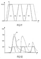
- the solenoid valve 5 is successively opened and closed by a series of pulses to which the crenellations 15 correspond.
- Fig.11 and 16 of Fig.12 of trapezoidal shape in this example (but can be as well square, triangular or sinusoidal).
- the flow of water during the backwash is typically 100 to 850 l / hm 2 (liters per hour and per m 2 of membrane area). The preferred values are between 250 and 400 l / hm 2 .
- the air velocity in the concentrated compartment is typically 0 to 4 Nm 3 / m 2 .s.
- the preferred values are between 0 and 1 Nm 3 / m 2 .s. (Zero speed corresponding to monophasic backwash periods) .
- the duration of the water + air phase is typically from 2 to 60 seconds. Preferred values are between 5 and 30 seconds.
- the duration of the "water only” phase is typically from 2 to 60 seconds, the preferred values being also between 5 and 30 seconds.
- Fig.6 corresponds to the end of the backwash with injection of water filtered through the orifice A, return to water of the casing C; all the valves are closed except for valve 7 and valve 4 which allows the purge of housing C.
- the patterns of Figs.7 to 10 illustrate a variant of operation corresponding to an air backwashing with water pulsation.
- the phase illustrated by Fig.8 . corresponds to a backwash only.
- the valve 5 ( Fig.1 ) is open for the admission of air by E2 and the valve 3 is also open for evacuation of the filter cake.
- the other valves are closed, in particular the valve 7.
- the air circulation continues as illustrated on Fig.8 but, in addition, filtered water is injected through the orifice A with pulsations produced by successive openings and closings of the solenoid valve 7 ( Fig.1 ), the pump 8 being in action.
- pulsations of backwash water correspond the slots 15 and 16 on Figs.11 and 12 .
- Fig.10 The last phase illustrated by Fig.10 . is identical to that of Fig.6 . and corresponds to an injection of filtered water with re-watering and purging.
- the cycles corresponding to the phases of the Figs.4 and 5 or some Figs.8 and 9 can be repeated several times.
- the number of cycles may vary from 1 to 10.
- the number of cycles will preferably be from 2 to 7.
- Fig.11 is a diagram illustrating the operation. On the abscissa is the time T, and on the ordinate the ratio (expressed as a percentage) of the flow rate of the fluid considered at the maximum flow rate of this fluid during the sequence.
- the areas marked "AA” correspond to pulsations, while the intervals are marked “BB”; the pulsations are two-phase with simultaneous injection of gas and water, while the injections are monophasic, either gas or water: the trapezoidal shape of the pulsations on Fig. 11 is only indicative; it could equally well be square, triangular or sinusoidal.
- the dotted envelope represents the continuous injection of one of the washing fluids, generally water, and the "saw teeth" correspond to the introduction of the second fluid, generally the gas: there is therefore many periods during which the second fluid is stopped, so zero flow, which justifies the speed range of 0 to 4 m / s.
- Fig.12 is a comparative diagram of releases of different modes of backwashing.
- the time T is plotted on the abscissa.
- On the ordinate are the concentrations of suspended solids in the rejections expressed in mg / l.
- the dashed curve 17 corresponds to an air and water backwash, without pulsation, for a water flow Q in constant backwash corresponding to the peaks of the crenellations 16.
- the dashed curve 18 corresponds to the concentrations of suspended solids in backflushing with pulsed water, according to the time slots 16.
- crenels 16 represent the backwash water flow on the ordinate and expressed in l / hm 2 (liters per hour and per m 2 ) as a function of the time T carried on the abscissa.
- Curve 17 shows that the effective phase of Backwashing with water and water without pulsation is limited in time to a very short period. The analysis of the phenomenon has led to the conclusion that the air and water mixture tends very rapidly towards a stabilized regime of ring flow type.
- the pulsations 16 according to the present invention favor and multiply the two-phase transition periods by varying the flow rate of the water, or the air injected, and by repeating this sequence several times.
- the curve 18 of the rejects according to the invention consists of three peaks corresponding to the three pulsations 16 of injected water.
- the backwashing without pulsation (curve 17) has only one peak corresponding substantially to the first peak of the curve 18. The concentration of suspended solids in the discharges then decreases constantly.
- Fig.13 is a comparative diagram of different modes of backwashing.
- the filtration time D expressed in weeks is plotted on the abscissa while the filter permeability E of the membrane expressed in l / hm 2 .bar (liters per hour, per m 2 of membrane and per bar) is plotted on the ordinate. The more the membrane is clogged, the lower the filtration permeability.
- Curve 19 corresponds to the case of pulsed water-air backwash according to the invention.
- the dashed curve 20 corresponds to the water-air backwashing without pulsation.
- Dotted curve 21 corresponds to the backwash with water alone.
- Curve 19 clearly shows that according to the invention, the permeability of the membrane filtration is maintained in time at a substantially constant level, thanks to efficient washing and declogging, much higher than that of the curves 20 and 21 which are decreasing with a steeper slope for the curve 21.
- the invention by associating pulsations of liquid with a continuous flow of gas, or pulsations de.gaz at a continuous liquid regime during backwashings of declogging of filtration membranes thus makes it possible to increase in a surprising and significant way removing the filter cake from a constant flow.
- the time between chemical regenerations is significantly increased.
- the time interval between two chemical regenerations is multiplied by 5 thanks to the invention, compared to a conventional method.
- the gain in permeability is increased, which makes it possible to reduce the frequency of application of this type of unclogging.
- the amount of water used is significantly reduced allowing a gain in productivity of the system.
Applications Claiming Priority (2)
| Application Number | Priority Date | Filing Date | Title |
|---|---|---|---|
| FR0402492A FR2867394B1 (fr) | 2004-03-10 | 2004-03-10 | Procede de nettoyage de membranes de filtration, et installation pour la mise en oeuvre de ce procede |
| PCT/FR2005/000486 WO2005097306A1 (fr) | 2004-03-10 | 2005-03-01 | Procede de nettoyage de membranes de filtration, et installation pour la mise en oeuvre de ce procede. |
Publications (2)
| Publication Number | Publication Date |
|---|---|
| EP1727613A1 EP1727613A1 (fr) | 2006-12-06 |
| EP1727613B1 true EP1727613B1 (fr) | 2010-09-08 |
Family
ID=34896430
Family Applications (1)
| Application Number | Title | Priority Date | Filing Date |
|---|---|---|---|
| EP05736520A Not-in-force EP1727613B1 (fr) | 2004-03-10 | 2005-03-01 | Procede de nettoyage de membranes de filtration, et installation pour la mise en oeuvre de ce procede. |
Country Status (12)
| Country | Link |
|---|---|
| US (1) | US20070187326A1 (ja) |
| EP (1) | EP1727613B1 (ja) |
| JP (1) | JP2007528290A (ja) |
| KR (1) | KR100860955B1 (ja) |
| CN (1) | CN1946472A (ja) |
| AT (1) | ATE480314T1 (ja) |
| AU (1) | AU2005230254B2 (ja) |
| CA (1) | CA2558441A1 (ja) |
| DE (2) | DE602005023424D1 (ja) |
| ES (1) | ES2273622T1 (ja) |
| FR (1) | FR2867394B1 (ja) |
| WO (1) | WO2005097306A1 (ja) |
Families Citing this family (19)
| Publication number | Priority date | Publication date | Assignee | Title |
|---|---|---|---|---|
| JP2007209964A (ja) | 2005-03-24 | 2007-08-23 | Ngk Insulators Ltd | 分離膜の洗浄方法 |
| DE102005015421B4 (de) * | 2005-04-04 | 2012-08-30 | Wehrle Umwelt Gmbh | Verfahren zur Abtrennung von Inhaltsstoffen aus einem fließfähigen Stoffgemisch und Anlage zur Durchführung derartiger Verfahren |
| JP5453711B2 (ja) * | 2006-03-29 | 2014-03-26 | 東レ株式会社 | 外圧式中空糸膜モジュールの洗浄方法 |
| US8574431B2 (en) * | 2008-03-18 | 2013-11-05 | Municipal Filtration Company, Llc | Filter system with gas agitation |
| GB0808464D0 (en) * | 2008-05-09 | 2008-06-18 | H2Oil & Gas Ltd | Filtration system |
| CN101284213B (zh) * | 2008-05-30 | 2011-08-03 | 北京汉青天朗水处理科技有限公司 | 一种清洗膜分离设备的方法及装置 |
| US8366654B2 (en) * | 2009-09-09 | 2013-02-05 | Stryker Corporation | Apparatus for preventing cross contamination by sterilizing an insufflation device |
| US20120211418A1 (en) * | 2011-02-18 | 2012-08-23 | Taiwan Semiconductor Manufacturing Company, Ltd. | Slurry Concentration System and Method |
| CN102923873A (zh) * | 2011-08-08 | 2013-02-13 | 曹健 | 一种铝型材表面处理在线水循环净化系统 |
| US10221084B1 (en) | 2011-09-06 | 2019-03-05 | Liberty Evans, Llc | Headworks and dewatering |
| DE102011056633B4 (de) | 2011-12-19 | 2014-02-13 | Highq-Factory Gmbh | Verfahren zum Reinigen eines Filters |
| US9968723B2 (en) * | 2013-01-08 | 2018-05-15 | Baxter International Inc. | System and method to efficiently clean a blood filter |
| AU2015337112A1 (en) | 2014-10-22 | 2017-05-18 | Koch Membrane Systems, Inc. | Membrane module system with bundle enclosures and pulsed aeration and method of operation |
| USD779631S1 (en) | 2015-08-10 | 2017-02-21 | Koch Membrane Systems, Inc. | Gasification device |
| CN108697989B (zh) * | 2016-03-04 | 2019-09-27 | 三菱电机株式会社 | 膜过滤装置、过滤膜清洗方法以及过滤膜的制造方法 |
| JP6362748B1 (ja) * | 2017-09-08 | 2018-07-25 | 株式会社クボタ | 膜分離システムおよび膜分離システムの膜モジュールの洗浄方法 |
| US11827537B2 (en) * | 2019-03-05 | 2023-11-28 | Aqua-Aerobic Systems, Inc. | System and method for removal of recalcitrant organic compounds from water |
| CN112973212B (zh) * | 2021-02-22 | 2022-08-05 | 宜宾丝丽雅股份有限公司 | 一种粘胶生产用滤芯的清洗方法 |
| CN117303508A (zh) * | 2023-10-26 | 2023-12-29 | 石家庄清流科技有限公司 | 污水单级薄膜过滤脉冲清堵机构 |
Family Cites Families (15)
| Publication number | Priority date | Publication date | Assignee | Title |
|---|---|---|---|---|
| US4414113A (en) * | 1982-09-29 | 1983-11-08 | Ecodyne Corporation | Liquid purification using reverse osmosis hollow fibers |
| JPH0671540B2 (ja) * | 1988-12-20 | 1994-09-14 | 株式会社東芝 | 中空糸膜フィルタの洗浄方法 |
| FR2668078B1 (fr) * | 1990-10-17 | 1992-12-24 | Dumez Lyonnaise Eaux | Procede pour le retrolavage de membrane tubulaires de filtration, et dispositif de mise en óoeuvre. |
| FR2674448B1 (fr) * | 1991-03-26 | 1994-03-25 | Dumez Lyonnaise Eaux | Procede de nettoyage de membranes tubulaires mesoporeuses d'ultrafiltration. |
| ES2145010T3 (es) * | 1991-08-07 | 2000-07-01 | Usf Filtration Limited | Concentracion de solidos en una suspension utilizando membranas de fibra huecas. |
| JP3091015B2 (ja) * | 1992-04-03 | 2000-09-25 | 日東電工株式会社 | 膜分離装置 |
| JPH07236818A (ja) * | 1994-02-25 | 1995-09-12 | Dick Deguremon Kk | 内圧式中空糸モジュールの逆洗方法 |
| JPH10464A (ja) * | 1996-06-18 | 1998-01-06 | Mitsubishi Heavy Ind Ltd | 逆浸透海水淡水化装置 |
| JPH10277539A (ja) * | 1997-04-10 | 1998-10-20 | Toray Ind Inc | 浄水器および非常用浄水機とその洗浄方法 |
| US20040007255A1 (en) * | 1997-06-20 | 2004-01-15 | Labib Mohamed Emam | Apparatus and method for cleaning pipelines, tubing and membranes using two-phase flow |
| US20040007525A1 (en) * | 1999-07-30 | 2004-01-15 | Rabie Hamid R. | Maintenance cleaning for membranes |
| JP2002248324A (ja) * | 2001-02-26 | 2002-09-03 | Kurita Water Ind Ltd | 膜分離装置及びその逆洗方法 |
| JP2003053160A (ja) * | 2001-08-14 | 2003-02-25 | Mitsubishi Rayon Co Ltd | 分離膜の洗浄方法及び膜濾過装置 |
| CN100518908C (zh) * | 2002-01-09 | 2009-07-29 | 美国海德能公司 | 用于改进空心纤维薄膜的过滤性能的方法 |
| JP2004073950A (ja) * | 2002-08-13 | 2004-03-11 | Asahi Kasei Chemicals Corp | 膜洗浄方法 |
-
2004
- 2004-03-10 FR FR0402492A patent/FR2867394B1/fr not_active Expired - Fee Related
-
2005
- 2005-03-01 DE DE602005023424T patent/DE602005023424D1/de active Active
- 2005-03-01 AU AU2005230254A patent/AU2005230254B2/en not_active Ceased
- 2005-03-01 ES ES05736520T patent/ES2273622T1/es active Pending
- 2005-03-01 DE DE05736520T patent/DE05736520T1/de active Pending
- 2005-03-01 JP JP2007502366A patent/JP2007528290A/ja active Pending
- 2005-03-01 WO PCT/FR2005/000486 patent/WO2005097306A1/fr active Application Filing
- 2005-03-01 US US10/592,152 patent/US20070187326A1/en not_active Abandoned
- 2005-03-01 KR KR1020067019682A patent/KR100860955B1/ko not_active IP Right Cessation
- 2005-03-01 AT AT05736520T patent/ATE480314T1/de not_active IP Right Cessation
- 2005-03-01 CN CNA2005800132300A patent/CN1946472A/zh active Pending
- 2005-03-01 EP EP05736520A patent/EP1727613B1/fr not_active Not-in-force
- 2005-03-01 CA CA002558441A patent/CA2558441A1/fr not_active Abandoned
Also Published As
| Publication number | Publication date |
|---|---|
| CA2558441A1 (fr) | 2005-10-20 |
| EP1727613A1 (fr) | 2006-12-06 |
| AU2005230254B2 (en) | 2010-11-18 |
| ES2273622T1 (es) | 2007-05-16 |
| KR20070005641A (ko) | 2007-01-10 |
| DE05736520T1 (de) | 2007-04-05 |
| DE602005023424D1 (de) | 2010-10-21 |
| FR2867394A1 (fr) | 2005-09-16 |
| JP2007528290A (ja) | 2007-10-11 |
| ATE480314T1 (de) | 2010-09-15 |
| KR100860955B1 (ko) | 2008-09-30 |
| FR2867394B1 (fr) | 2006-12-15 |
| AU2005230254A1 (en) | 2005-10-20 |
| WO2005097306A1 (fr) | 2005-10-20 |
| CN1946472A (zh) | 2007-04-11 |
| US20070187326A1 (en) | 2007-08-16 |
Similar Documents
| Publication | Publication Date | Title |
|---|---|---|
| EP1727613B1 (fr) | Procede de nettoyage de membranes de filtration, et installation pour la mise en oeuvre de ce procede. | |
| CN1114468C (zh) | 用薄膜过滤从液体中去掉漂浮物质和盐类的方法和装置 | |
| JP3198923B2 (ja) | 膜の洗浄方法 | |
| FR2674448A1 (fr) | Procede de nettoyage de membranes tubulaires mesoporeuses d'ultrafiltration. | |
| EP0213157A1 (en) | CONCENTRATION OF SOLIDS IN A SUSPENSION. | |
| JP2003266072A (ja) | 膜ろ過方法 | |
| CN112299510B (zh) | 净水机、净水系统及其控制方法 | |
| JP4251879B2 (ja) | 分離膜モジュールの運転方法 | |
| JP4225471B2 (ja) | 多段式分離膜モジュールの運転方法 | |
| EP0470015B1 (fr) | Procédé de décolmatage en microfiltration tangentielle | |
| WO2004022206A1 (ja) | 分離膜モジュール及び分離膜モジュールの運転方法 | |
| CN1429132A (zh) | 净化水的方法和设备 | |
| EP0526372A1 (fr) | Procédé et dispositif de décolmatage de membranes de filtration | |
| JP5017922B2 (ja) | 水処理方法 | |
| JP6653154B2 (ja) | 中空糸膜モジュールの洗浄方法及び濾過装置 | |
| WO2007017017A1 (en) | Method for backwashing capillary membranes of a membrane system | |
| EP1304157B1 (fr) | Procédé de nettoyage d'une membrane céramique utilisée dans le filtration du vin | |
| JP2000246069A (ja) | 膜ろ過装置 | |
| JP4605951B2 (ja) | 膜濾過システムおよびその運転方法 | |
| JP7067678B1 (ja) | 濾過膜の洗浄装置、水処理装置及び濾過膜の洗浄方法 | |
| JP2002326005A (ja) | 濾過装置の目詰まり防止方法及び目詰まり防止システムを具えた濾過装置 | |
| JP6693775B2 (ja) | 濾過装置、濾過方法および水処理システム | |
| JP2000210540A (ja) | 膜ろ過装置 | |
| JP2006198531A (ja) | 中空糸膜モジュールの運転方法 | |
| EP4342574A2 (fr) | Procede de gestion du colmatage de membrane d'un dispositif de filtration tangentielle |
Legal Events
| Date | Code | Title | Description |
|---|---|---|---|
| PUAI | Public reference made under article 153(3) epc to a published international application that has entered the european phase |
Free format text: ORIGINAL CODE: 0009012 |
|
| 17P | Request for examination filed |
Effective date: 20060911 |
|
| AK | Designated contracting states |
Kind code of ref document: A1 Designated state(s): AT BE BG CH CY CZ DE DK EE ES FI FR GB GR HU IE IS IT LI LT LU MC NL PL PT RO SE SI SK TR |
|
| TCNL | Nl: translation of patent claims filed | ||
| DET | De: translation of patent claims | ||
| REG | Reference to a national code |
Ref country code: HU Ref legal event code: AG9A |
|
| DAX | Request for extension of the european patent (deleted) | ||
| 17Q | First examination report despatched |
Effective date: 20080215 |
|
| GRAP | Despatch of communication of intention to grant a patent |
Free format text: ORIGINAL CODE: EPIDOSNIGR1 |
|
| GRAS | Grant fee paid |
Free format text: ORIGINAL CODE: EPIDOSNIGR3 |
|
| GRAA | (expected) grant |
Free format text: ORIGINAL CODE: 0009210 |
|
| AK | Designated contracting states |
Kind code of ref document: B1 Designated state(s): AT BE BG CH CY CZ DE DK EE ES FI FR GB GR HU IE IS IT LI LT LU MC NL PL PT RO SE SI SK TR |
|
| REG | Reference to a national code |
Ref country code: GB Ref legal event code: FG4D Free format text: NOT ENGLISH |
|
| REG | Reference to a national code |
Ref country code: CH Ref legal event code: EP |
|
| REG | Reference to a national code |
Ref country code: IE Ref legal event code: FG4D Free format text: LANGUAGE OF EP DOCUMENT: FRENCH |
|
| REF | Corresponds to: |
Ref document number: 602005023424 Country of ref document: DE Date of ref document: 20101021 Kind code of ref document: P |
|
| REG | Reference to a national code |
Ref country code: NL Ref legal event code: T3 |
|
| PG25 | Lapsed in a contracting state [announced via postgrant information from national office to epo] |
Ref country code: FI Free format text: LAPSE BECAUSE OF FAILURE TO SUBMIT A TRANSLATION OF THE DESCRIPTION OR TO PAY THE FEE WITHIN THE PRESCRIBED TIME-LIMIT Effective date: 20100908 Ref country code: AT Free format text: LAPSE BECAUSE OF FAILURE TO SUBMIT A TRANSLATION OF THE DESCRIPTION OR TO PAY THE FEE WITHIN THE PRESCRIBED TIME-LIMIT Effective date: 20100908 Ref country code: LT Free format text: LAPSE BECAUSE OF FAILURE TO SUBMIT A TRANSLATION OF THE DESCRIPTION OR TO PAY THE FEE WITHIN THE PRESCRIBED TIME-LIMIT Effective date: 20100908 |
|
| LTIE | Lt: invalidation of european patent or patent extension |
Effective date: 20100908 |
|
| PG25 | Lapsed in a contracting state [announced via postgrant information from national office to epo] |
Ref country code: PL Free format text: LAPSE BECAUSE OF FAILURE TO SUBMIT A TRANSLATION OF THE DESCRIPTION OR TO PAY THE FEE WITHIN THE PRESCRIBED TIME-LIMIT Effective date: 20100908 Ref country code: SI Free format text: LAPSE BECAUSE OF FAILURE TO SUBMIT A TRANSLATION OF THE DESCRIPTION OR TO PAY THE FEE WITHIN THE PRESCRIBED TIME-LIMIT Effective date: 20100908 Ref country code: CY Free format text: LAPSE BECAUSE OF FAILURE TO SUBMIT A TRANSLATION OF THE DESCRIPTION OR TO PAY THE FEE WITHIN THE PRESCRIBED TIME-LIMIT Effective date: 20100908 |
|
| REG | Reference to a national code |
Ref country code: IE Ref legal event code: FD4D |
|
| PG25 | Lapsed in a contracting state [announced via postgrant information from national office to epo] |
Ref country code: GR Free format text: LAPSE BECAUSE OF FAILURE TO SUBMIT A TRANSLATION OF THE DESCRIPTION OR TO PAY THE FEE WITHIN THE PRESCRIBED TIME-LIMIT Effective date: 20101209 Ref country code: SE Free format text: LAPSE BECAUSE OF FAILURE TO SUBMIT A TRANSLATION OF THE DESCRIPTION OR TO PAY THE FEE WITHIN THE PRESCRIBED TIME-LIMIT Effective date: 20100908 |
|
| PG25 | Lapsed in a contracting state [announced via postgrant information from national office to epo] |
Ref country code: IE Free format text: LAPSE BECAUSE OF FAILURE TO SUBMIT A TRANSLATION OF THE DESCRIPTION OR TO PAY THE FEE WITHIN THE PRESCRIBED TIME-LIMIT Effective date: 20100908 |
|
| PG25 | Lapsed in a contracting state [announced via postgrant information from national office to epo] |
Ref country code: RO Free format text: LAPSE BECAUSE OF FAILURE TO SUBMIT A TRANSLATION OF THE DESCRIPTION OR TO PAY THE FEE WITHIN THE PRESCRIBED TIME-LIMIT Effective date: 20100908 Ref country code: EE Free format text: LAPSE BECAUSE OF FAILURE TO SUBMIT A TRANSLATION OF THE DESCRIPTION OR TO PAY THE FEE WITHIN THE PRESCRIBED TIME-LIMIT Effective date: 20100908 Ref country code: IS Free format text: LAPSE BECAUSE OF FAILURE TO SUBMIT A TRANSLATION OF THE DESCRIPTION OR TO PAY THE FEE WITHIN THE PRESCRIBED TIME-LIMIT Effective date: 20110108 Ref country code: PT Free format text: LAPSE BECAUSE OF FAILURE TO SUBMIT A TRANSLATION OF THE DESCRIPTION OR TO PAY THE FEE WITHIN THE PRESCRIBED TIME-LIMIT Effective date: 20110110 Ref country code: SK Free format text: LAPSE BECAUSE OF FAILURE TO SUBMIT A TRANSLATION OF THE DESCRIPTION OR TO PAY THE FEE WITHIN THE PRESCRIBED TIME-LIMIT Effective date: 20100908 Ref country code: IT Free format text: LAPSE BECAUSE OF FAILURE TO SUBMIT A TRANSLATION OF THE DESCRIPTION OR TO PAY THE FEE WITHIN THE PRESCRIBED TIME-LIMIT Effective date: 20100908 Ref country code: CZ Free format text: LAPSE BECAUSE OF FAILURE TO SUBMIT A TRANSLATION OF THE DESCRIPTION OR TO PAY THE FEE WITHIN THE PRESCRIBED TIME-LIMIT Effective date: 20100908 |
|
| PGFP | Annual fee paid to national office [announced via postgrant information from national office to epo] |
Ref country code: NL Payment date: 20110316 Year of fee payment: 7 |
|
| PLBE | No opposition filed within time limit |
Free format text: ORIGINAL CODE: 0009261 |
|
| STAA | Information on the status of an ep patent application or granted ep patent |
Free format text: STATUS: NO OPPOSITION FILED WITHIN TIME LIMIT |
|
| PGFP | Annual fee paid to national office [announced via postgrant information from national office to epo] |
Ref country code: GB Payment date: 20110321 Year of fee payment: 7 |
|
| 26N | No opposition filed |
Effective date: 20110609 |
|
| PG25 | Lapsed in a contracting state [announced via postgrant information from national office to epo] |
Ref country code: DK Free format text: LAPSE BECAUSE OF FAILURE TO SUBMIT A TRANSLATION OF THE DESCRIPTION OR TO PAY THE FEE WITHIN THE PRESCRIBED TIME-LIMIT Effective date: 20100908 |
|
| BERE | Be: lapsed |
Owner name: DEGREMONT Effective date: 20110331 |
|
| REG | Reference to a national code |
Ref country code: DE Ref legal event code: R097 Ref document number: 602005023424 Country of ref document: DE Effective date: 20110609 |
|
| PG25 | Lapsed in a contracting state [announced via postgrant information from national office to epo] |
Ref country code: MC Free format text: LAPSE BECAUSE OF NON-PAYMENT OF DUE FEES Effective date: 20110331 |
|
| REG | Reference to a national code |
Ref country code: CH Ref legal event code: PL |
|
| PG25 | Lapsed in a contracting state [announced via postgrant information from national office to epo] |
Ref country code: BE Free format text: LAPSE BECAUSE OF NON-PAYMENT OF DUE FEES Effective date: 20110331 |
|
| PG25 | Lapsed in a contracting state [announced via postgrant information from national office to epo] |
Ref country code: LI Free format text: LAPSE BECAUSE OF NON-PAYMENT OF DUE FEES Effective date: 20110331 Ref country code: CH Free format text: LAPSE BECAUSE OF NON-PAYMENT OF DUE FEES Effective date: 20110331 |
|
| PGFP | Annual fee paid to national office [announced via postgrant information from national office to epo] |
Ref country code: DE Payment date: 20120515 Year of fee payment: 8 |
|
| REG | Reference to a national code |
Ref country code: NL Ref legal event code: V1 Effective date: 20121001 |
|
| GBPC | Gb: european patent ceased through non-payment of renewal fee |
Effective date: 20120301 |
|
| PG25 | Lapsed in a contracting state [announced via postgrant information from national office to epo] |
Ref country code: GB Free format text: LAPSE BECAUSE OF NON-PAYMENT OF DUE FEES Effective date: 20120301 |
|
| PG25 | Lapsed in a contracting state [announced via postgrant information from national office to epo] |
Ref country code: NL Free format text: LAPSE BECAUSE OF NON-PAYMENT OF DUE FEES Effective date: 20121001 |
|
| PGFP | Annual fee paid to national office [announced via postgrant information from national office to epo] |
Ref country code: FR Payment date: 20130214 Year of fee payment: 9 |
|
| PG25 | Lapsed in a contracting state [announced via postgrant information from national office to epo] |
Ref country code: LU Free format text: LAPSE BECAUSE OF NON-PAYMENT OF DUE FEES Effective date: 20110301 |
|
| PG25 | Lapsed in a contracting state [announced via postgrant information from national office to epo] |
Ref country code: TR Free format text: LAPSE BECAUSE OF FAILURE TO SUBMIT A TRANSLATION OF THE DESCRIPTION OR TO PAY THE FEE WITHIN THE PRESCRIBED TIME-LIMIT Effective date: 20100908 Ref country code: BG Free format text: LAPSE BECAUSE OF FAILURE TO SUBMIT A TRANSLATION OF THE DESCRIPTION OR TO PAY THE FEE WITHIN THE PRESCRIBED TIME-LIMIT Effective date: 20101208 |
|
| PG25 | Lapsed in a contracting state [announced via postgrant information from national office to epo] |
Ref country code: HU Free format text: LAPSE BECAUSE OF FAILURE TO SUBMIT A TRANSLATION OF THE DESCRIPTION OR TO PAY THE FEE WITHIN THE PRESCRIBED TIME-LIMIT Effective date: 20100908 |
|
| REG | Reference to a national code |
Ref country code: DE Ref legal event code: R119 Ref document number: 602005023424 Country of ref document: DE Effective date: 20131001 |
|
| PG25 | Lapsed in a contracting state [announced via postgrant information from national office to epo] |
Ref country code: DE Free format text: LAPSE BECAUSE OF NON-PAYMENT OF DUE FEES Effective date: 20131001 |
|
| PG25 | Lapsed in a contracting state [announced via postgrant information from national office to epo] |
Ref country code: ES Free format text: LAPSE BECAUSE OF FAILURE TO SUBMIT A TRANSLATION OF THE DESCRIPTION OR TO PAY THE FEE WITHIN THE PRESCRIBED TIME-LIMIT Effective date: 20100908 |
|
| REG | Reference to a national code |
Ref country code: FR Ref legal event code: ST Effective date: 20141128 |
|
| PG25 | Lapsed in a contracting state [announced via postgrant information from national office to epo] |
Ref country code: FR Free format text: LAPSE BECAUSE OF NON-PAYMENT OF DUE FEES Effective date: 20140331 |
|
| P01 | Opt-out of the competence of the unified patent court (upc) registered |
Effective date: 20230601 |