EP1727166A1 - Element de stockage d'energie et condensateur double couche electrique - Google Patents
Element de stockage d'energie et condensateur double couche electrique Download PDFInfo
- Publication number
- EP1727166A1 EP1727166A1 EP05703986A EP05703986A EP1727166A1 EP 1727166 A1 EP1727166 A1 EP 1727166A1 EP 05703986 A EP05703986 A EP 05703986A EP 05703986 A EP05703986 A EP 05703986A EP 1727166 A1 EP1727166 A1 EP 1727166A1
- Authority
- EP
- European Patent Office
- Prior art keywords
- graphite
- electrode
- double layer
- electric double
- layer capacitor
- Prior art date
- Legal status (The legal status is an assumption and is not a legal conclusion. Google has not performed a legal analysis and makes no representation as to the accuracy of the status listed.)
- Withdrawn
Links
Images


Classifications
-
- H—ELECTRICITY
- H01—ELECTRIC ELEMENTS
- H01G—CAPACITORS; CAPACITORS, RECTIFIERS, DETECTORS, SWITCHING DEVICES OR LIGHT-SENSITIVE DEVICES, OF THE ELECTROLYTIC TYPE
- H01G11/00—Hybrid capacitors, i.e. capacitors having different positive and negative electrodes; Electric double-layer [EDL] capacitors; Processes for the manufacture thereof or of parts thereof
- H01G11/22—Electrodes
- H01G11/30—Electrodes characterised by their material
- H01G11/32—Carbon-based
- H01G11/34—Carbon-based characterised by carbonisation or activation of carbon
-
- H—ELECTRICITY
- H01—ELECTRIC ELEMENTS
- H01G—CAPACITORS; CAPACITORS, RECTIFIERS, DETECTORS, SWITCHING DEVICES OR LIGHT-SENSITIVE DEVICES, OF THE ELECTROLYTIC TYPE
- H01G11/00—Hybrid capacitors, i.e. capacitors having different positive and negative electrodes; Electric double-layer [EDL] capacitors; Processes for the manufacture thereof or of parts thereof
- H01G11/04—Hybrid capacitors
- H01G11/06—Hybrid capacitors with one of the electrodes allowing ions to be reversibly doped thereinto, e.g. lithium ion capacitors [LIC]
-
- H—ELECTRICITY
- H01—ELECTRIC ELEMENTS
- H01G—CAPACITORS; CAPACITORS, RECTIFIERS, DETECTORS, SWITCHING DEVICES OR LIGHT-SENSITIVE DEVICES, OF THE ELECTROLYTIC TYPE
- H01G11/00—Hybrid capacitors, i.e. capacitors having different positive and negative electrodes; Electric double-layer [EDL] capacitors; Processes for the manufacture thereof or of parts thereof
- H01G11/22—Electrodes
- H01G11/30—Electrodes characterised by their material
- H01G11/32—Carbon-based
-
- H—ELECTRICITY
- H01—ELECTRIC ELEMENTS
- H01G—CAPACITORS; CAPACITORS, RECTIFIERS, DETECTORS, SWITCHING DEVICES OR LIGHT-SENSITIVE DEVICES, OF THE ELECTROLYTIC TYPE
- H01G11/00—Hybrid capacitors, i.e. capacitors having different positive and negative electrodes; Electric double-layer [EDL] capacitors; Processes for the manufacture thereof or of parts thereof
- H01G11/54—Electrolytes
- H01G11/56—Solid electrolytes, e.g. gels; Additives therein
-
- H—ELECTRICITY
- H01—ELECTRIC ELEMENTS
- H01G—CAPACITORS; CAPACITORS, RECTIFIERS, DETECTORS, SWITCHING DEVICES OR LIGHT-SENSITIVE DEVICES, OF THE ELECTROLYTIC TYPE
- H01G11/00—Hybrid capacitors, i.e. capacitors having different positive and negative electrodes; Electric double-layer [EDL] capacitors; Processes for the manufacture thereof or of parts thereof
- H01G11/54—Electrolytes
- H01G11/58—Liquid electrolytes
- H01G11/62—Liquid electrolytes characterised by the solute, e.g. salts, anions or cations therein
-
- Y—GENERAL TAGGING OF NEW TECHNOLOGICAL DEVELOPMENTS; GENERAL TAGGING OF CROSS-SECTIONAL TECHNOLOGIES SPANNING OVER SEVERAL SECTIONS OF THE IPC; TECHNICAL SUBJECTS COVERED BY FORMER USPC CROSS-REFERENCE ART COLLECTIONS [XRACs] AND DIGESTS
- Y02—TECHNOLOGIES OR APPLICATIONS FOR MITIGATION OR ADAPTATION AGAINST CLIMATE CHANGE
- Y02E—REDUCTION OF GREENHOUSE GAS [GHG] EMISSIONS, RELATED TO ENERGY GENERATION, TRANSMISSION OR DISTRIBUTION
- Y02E60/00—Enabling technologies; Technologies with a potential or indirect contribution to GHG emissions mitigation
- Y02E60/13—Energy storage using capacitors
Definitions
- the present invention relates to power storage elements, and particularly to electric double layer capacitors.
- the invention relates to electric double layer capacitors with a large electrostatic capacitance.
- an electric double layer capacitor with an electrostatic capacitance greater than those of electric double layer capacitors using conventional activated carbon has been proposed to be provided by using, as a carbon material for constituting a polarizable electrode, a carbon material being produced by performing a heat treatment together with at least one of an alkali metal and an alkali metal compound, the heat treatment being conducted at a temperature which is not less than a temperature at which a vapor of the alkali metal is generated; and developing an electrostatic capacitance through application of a voltage of not less than a rated voltage firstly between the polarizable electrodes after assembling the electric double layer capacitor so that ions of a solute of the organic electrolytic solution are inserted into a space between microcrystalline carbon layers composed of the carbon material (see, for example, Patent Document 1).
- Patent Document 1 Japanese Patent Laid-Open Publication No. 2000-77273
- a problem of the present invention is to provide an electric double layer capacitor which has an electrostatic capacitance per unit volume larger than that of conventional electric double layer capacitors and which has a high withstand voltage and a large electrostatic energy per unit volume.
- an electric double layer capacitor comprising carbonaceous electrodes immersed in an electrolytic solution, wherein at least one electrode comprises graphite of which changing rate in voltage turns smaller than a voltage changing curve based on a time constant through intake of ions in the electrolytic solution into the graphite in the course of charging at the time of charging with a constant current, and wherein charging/discharging is performed through adsorption and desorption of the ions.
- the aforementioned electric double layer capacitor using graphite in both the positive electrode and the negative electrode.
- the aforementioned electric double layer capacitor wherein one electrode is composed of a carbon electrode comprising graphite-like microcrystalline carbon of which electrostatic capacitance has been developed through insertion of ions at a first charging, and the carbon therefore showing a voltage changing curve based on a time constant at a second and subsequent charging with a constant current. Further, provided is the aforementioned electric double layer capacitor wherein the graphite electrode has a volume smaller than that of the counter carbon electrode.
- At least one electrode comprises a mixture of graphite of which changing rate in voltage turns smaller than a voltage changing curve based on a time constant through intake of ions in the electrolytic solution into the graphite in the course of charging at the time of charging with a constant current, and graphite-like microcrystalline carbon of which electrostatic capacitance has been developed through insertion of ions at a first charging, and the carbon therefore showing a voltage changing curve based on a time constant at a second and subsequent charging with a constant current.
- the electrolytic solution comprises an ion of which maximum interatomic distance on a minimum projection plane of a molecule is 0.7 nm or less.
- the electrolytic solution uses an electrolytic solution prepared by dissolving at least one species selected from tetrafluoroborate or hexafluorophosphate of an quaternary ammonium and its derivatives in aprotic solvents.
- the quaternary ammonium is at least one species selected from the group consisting of pyrrolidinium compounds represented by formula
- R is each independently an alkyl group having from 1 to 10 carbon atoms or R and R form together an alkylene group having 3 to 8 carbon atoms; and spiro-(1,1')bipyrrolidinium, dimethylpyrrolidinium, diethylpyrrolidinium, ethylmethylpyrrolidinium, spiro-bipyridinium, tetramethylphosphonium, tetraethylphosphonium, trimethylalkylammonium in which the alkyl groups have from 2 to 10 carbon atoms.
- the quaternary ammonium is piperidine-1-spiro-1'-pyrrohdinium.
- the electrolytic solution comprises 1.5 M/L or more of a solute selected from the group consisting of spiro-(1,1')bipyrrolidinium tetrafluoroborate, spiro-(1,1')bipyrrolidinium hexafluorophosphate, piperidine-1-spiro-1'-pyrrolidinium tetrafluoroborate and piperidine-1-spiro-1'-pyrrolidinium hexafluorophosphate, and a mixed solvent of at least two species selected from the group consisting of propylene carbonate (PC), ethylene carbonate (EC) and diethyl carbonate (DEC).
- PC propylene carbonate
- EC ethylene carbonate
- DEC diethyl carbonate
- the aforementioned electric double layer capacitor wherein the graphite has an I(1360)/I(1580) peak ratio determined by Raman spectroscopy within the range of from 0.05 to 0.25.
- the aforementioned electric double layer capacitor wherein the graphite has a hexagonal crystal-to-rhombohedral crystal ratio (Ib/Ia ratio) determined by X-ray diffractometry of 0.3 or more.
- the aforementioned electric double layer capacitor which works in a potential range of from +0.5 V to +6 V based on the oxidation-reduction potential of lithium.
- electric double layer capacitors of the present invention have a large electrostatic capacitance per unit volume and a high withstand voltage and, therefore, can store a large amount of electrostatic energy; thus, it is possible to provide electric double layer capacitors useful for electric power sources for transportation vehicles such as electric cars, electric power storage systems for the electric power industry, etc.
- Fig. 1 shows charging/discharging curves of an electric double layer capacitor of the present invention and an electric double layer capacitor of a prior art example.
- Fig. 1(A) which shows a charging/discharging curve of an electric double layer capacitor of the present invention, is characterized in that when charging is conducted with a constant current at the first charging, the voltage change with respect to time, the changing rate in voltage is larger than the voltage changing rate based on a time constant in an initial stage of the charging, and there is an inflection point C 1 where the changing rate turns smaller than the voltage changing rate based on a time constant due to the increase in voltage, and there is an inflection point C2 where a similar behavior is shown in the second and subsequent charging.
- the phenomenon found in a voltage changing curve at the first charging is considered to be an electric current caused by the driving force for permeation of the electrolytic solution into minute pores in the electric double layer capacitor and insertion of ions to carbon. No inflection point is found in the voltage changing curves in the course of the second and subsequent charging with a constant current.
- Graphite electrodes of the present invention have a larger electrostatic capacitance compared with electrodes made of activated carbon or carbon having micropores formed by initial charging. Therefore, when an electrode of activated carbon or the like is used as a counter electrode, in order to obtain an electrostatic capacitance corresponding to such an electrode of activated carbon or the like, graphite electrodes may have a greatly reduced thickness in comparison to electrodes of activated carbon or the like.
- graphite applicable to the present invention is graphite in which there is disorder in graphite layers.
- the disorder in graphite layers was quantified by measuring the ratio of a peak at 1360 cm -1 to a peak at 1580 cm -1 by Raman spectroscopy
- the ratio of I (1360)/I (1580) is between 0.02 and 0.3, and preferably near 0.15. If the ratio is less than 0.02 or more than 0.3, it is impossible to obtain a sufficient electrostatic capacitance.
- one having a ratio of hexagonal crystals to rhombohedral crystals namely, a hexagonal crystal/rhombohedral crystal ratio (Ib/Ia) of 0.3 or more is the most preferred.
- a ratio of hexagonal crystals to rhombohedral crystals namely, a hexagonal crystal/rhombohedral crystal ratio (Ib/Ia) of 0.3 or more is the most preferred.
- Use of one having a ratio less than 0.3 will result in a failure in obtaining a sufficient electrostatic capacitance.
- Carbon material which is a negative electrode material for lithium-ion batteries is the one which developes characteristic as a negative electrode of a battery through insertion of lithium into the carbon material at a potential of +0.25 V or less based on the lithium oxidation-reduction potential.
- the operation potential of a graphite electrode is within a potential range of from +0.5 V to +6 V, preferably from +0.5 V to +5.5V, and more preferably from +0.5 V to 5.0 V based on the lithium oxidation-reduction potential, and it is thought that the electrode works differently in a different region from the carbon material which is a negative electrode material for lithium-ion batteries.
- desirable features of the present invention are particle diameter: 1 ⁇ m to 20 ⁇ m, interlayer spacing: 0.3354 to 0.3390 nm, and Lc: 50 to 100 nm.
- a carbon material other than graphite when used as one electrode, examples thereof include carbon materials having graphite-like microcrystalline carbon prepared by heat-treating a raw material such as petroleum-based carbon materials, e.g., petroleum pitch and petroleum coke, carboniferous carbon materials, e.g., coal pitch and coal coke, wood-based carbon materials, e.g., coconut shell and sawdust, resin-based carbon materials, e.g., phenol resin, polyvinyl chloride, polyvinylidene chloride and polyimide, with at least one species selected from alkali metal and/or alkali metal compounds at a temperature not lower than the temperature at which vapor of alkali metal is formed.
- a raw material such as petroleum-based carbon materials, e.g., petroleum pitch and petroleum coke, carboniferous carbon materials, e.g., coal pitch and coal coke, wood-based carbon materials, e.g., coconut shell and sawdust
- resin-based carbon materials e.g.,
- a resulting electrode is activated by the application of electric current at the time of initial charging, thereby developing an electrostatic capacitance as an electric double layer capacitor. Further, activated carbon having a surface area of from 1000 m 2 /g to 3000 m 2 /g may be used.
- an electrolytic solution which can be used in the present invention, one prepared by dissolving a solute in a nonaqueous solvent may be used.
- one containing an ion of which maximum interatomic distance on a minimum projection plane of a molecule is 0.7 nm or less is preferable as the electrolytic solution because it is inserted into a carbon material to make an electric double layer capacitor have a large capacitance.
- examples of the anion which works in an electrolytic solution include at least one species selected from the group consisting of tetrafluoroborate ion (BF 4 - ), hexafluorophosphate ion (PF 6 - ), perchlorate ion (C10 4 -), hexafluoroarsenate (AsF 6 - ), hexafluoroantimonate (SbF 6 - ), perfluoromethylsulfonyl (CF 3 SO 2 - ) and perfluoromethylsulfonate (CF 3 SO 3 - ).
- tetrafluoroborate ion BF 4 -
- PF 6 - hexafluorophosphate ion
- C10 4 - perchlorate ion
- AsF 6 - hexafluoroarsenate
- SBF 6 - hexafluoroantimonate
- CF 3 SO 2 - perfluoromethyls
- the cation is selected from the group consisting of symmetric or ansymmetric quaternary ammonium ions, ions of imidazolium derivatives such as ethylmethylimidazolium and spiro-(1,1')bipyrollidinium and lithium ion.
- Particular examples include at least one species selected from the group consisting of triethylmethylammonium ion, the above-mentioned pyrrolidinium compounds, spiro-(1,1')bipyrrolidinium, dimethylpyrrolidinium, diethylpyrrolidinium, ethylmethylpyrrolidinium, spiro-bipyridinium, tetramethylphosphonium, tetraethylphosphonium and trimethylalkylammonium in which the alkyl groups have from 2 to 10 carbon atoms. These molecules have a small minimum projection area and develop a large capacitance when being inserted between layers of a carbon material.
- nonaqueous solvent As a nonaqueous solvent, at least one species selected from the group consisting of tetrahydrofuran (THF), methyltetrahydrofuran (MeTHF), methylformamide, methyl acetate, diethyl carbonate, dimethyl ether (DME), propylene carbonate (PC), ⁇ -butyrolactone (GBL), dimethyl carbonate (DMC), ethylene carbonate (EC), acetonitrile (AN), sulfolane (SL), or such nonaqueous solvents having halogen in part of their molecules may be selected.
- THF tetrahydrofuran
- MeTHF methyltetrahydrofuran
- MeTHF methylformamide
- methyl acetate diethyl carbonate
- DME dimethyl ether
- PC propylene carbonate
- GBL ⁇ -butyrolactone
- DMC dimethyl carbonate
- EC ethylene carbonate
- AN acetonitrile
- both a solvent and a solute need to have a potential window of from -1.6 V to +1.5 V or more.
- Preferred anions are therefore tetrafluoroborate ion (BF 4 - ), hexafluorophosphate ion (PF 6 - ) and perchlorate ion (ClO 4 - ).
- Preferred cations are pyrrolidinium ions such as the aforementioned pyrrolidinium compounds, spiro-(1,1')bipyrrolidinium, piperidine-1-spiro-1'-pyrrolidinium, dimethylpyrrolidinium, diethylpyrrolidinium, ethylmethylpyrrolidinium and spiro-bipyridinium, and tetramethylphosphonium and tetraethylphosphonium.
- pyrrolidinium ions such as the aforementioned pyrrolidinium compounds, spiro-(1,1')bipyrrolidinium, piperidine-1-spiro-1'-pyrrolidinium, dimethylpyrrolidinium, diethylpyrrolidinium, ethylmethylpyrrolidinium and spiro-bipyridinium, and tetramethylphosphonium and tetraethylphosphonium.
- Preferred solvents are at least one species selected from acetonitrile (AN), propylene carbonate (PC), ethylene carbonate (EC), dimethyl carbonate (DMC) and diethyl carbonate (DEC), which have a potential window about from -3 V to +3.5 V.
- AN acetonitrile
- PC propylene carbonate
- EC ethylene carbonate
- DMC dimethyl carbonate
- DEC diethyl carbonate
- the electrolytic solution may contain an additive which decomposes within a range of from +1 V to +5 V on the basis of the oxidation-reduction potential of lithium and which forms an ion-permeable film on the surface of a graphite electrode.
- charging may be conducted in a temperature atmosphere of from 30°C to 100°C.
- Graphite electrode 2 was produced in the same manner as that of the preparation of graphite electrode 1 except for using graphite having a Raman ratio of 0.05, a rhombohedral crystal ratio of 0, an average particle diameter of 3.0 ⁇ m, an interlayer spacing of 0.354 nm and a specific surface area of 13 m 2 /g, like Graphite 2 given in Table 1, in place of the graphite used in the preparation 1 of graphite electrode.
- Graphite electrode 3 was produced in the same manner as that of the preparation of graphite electrode 1 except for using graphite having a Raman ratio of 0.06, a rhombohedral crystal ratio of 0.53, an average particle diameter of 3.0 ⁇ m, an interlayer spacing of 0.354 nm and a specific surface area of 5 m 2 /g, like Graphite 3 given in Table 1, in place of the graphite used in the preparation 1 of graphite electrode.
- Graphite electrode 4 was produced in the same manner as that of the preparation of graphite electrode 1 except for using graphite having a Raman ratio of 0.05, a rhombohedral crystal ratio of 0, an average particle diameter of 3.0 ⁇ m, an interlayer spacing of 0.354 nm and a specific surface area of 15 m 2 /g, like Graphite 4 given in Table 1, in place of the graphite used in the preparation 1 of graphite electrode.
- Graphite electrode 5 was produced in the same manner as that of the preparation of graphite electrode 1 except for using a graphite having a Raman ratio of 0.05, a rhombohedral crystal ratio of 0, an average particle diameter of 2.5 ⁇ m, an interlayer spacing of 0.355 nm and a specific surface area of 5 m 2 /g, like Graphite 5 given in Table 1, in place of the graphite used in the preparation 1 of graphite electrode.
- Graphite electrode was produced in the same manner as that of the preparation of graphite electrode 1 except for using graphite having a Raman ratio of 0.19, a rhombohedral crystal ratio of 0.33, an average particle diameter of 0.5 ⁇ m and a specific surface area of 300 m 2 /g, like Graphite 6 given in Table 1, in place of the graphite used in the preparation 1 of graphite electrode.
- Graphite electrode 7 was produced in the same manner as that of the preparation of graphite electrode 1 except for using carbon having a Raman ratio of 0.16, a rhombohedral crystal ratio of 0, an average particle diameter of 5 ⁇ m and a specific surface area of 15 m 2 /g, like Graphite 7 given in Table 1, which was prepared by calcining mesophase carbon MCMB at 2800°C for 15 hours, in place of the graphite used in the preparation 1 of graphite electrode.
- Graphite electrode 8 was produced in the same manner as that of the preparation of graphite electrode 1 except for using graphite having a Raman ratio of 0.26, a rhombohedral crystal ratio of 0.31, an average particle diameter of 3 ⁇ m and a specific surface area of 80 m 2 /g, like Graphite 8 given in Table 1, in place of the graphite used in the preparation 1 of graphite electrode.
- Graphite electrode 8 was produced in the same manner as that of the preparation of graphite electrode 1 except for using graphite having a Raman ratio of 0.03, a rhombohedral crystal ratio of 0.19, an average particle diameter of 5 ⁇ m and a specific surface area of 12 m 2 /g, like Graphite 9 given in Table 1, in place of the graphite used in the preparation 1 of graphite electrode.
- Graphite 1 came to develop a capacitance rapidly near 4.5 V on the basis of the counter lithium metal and an electric capacitance of about 25 mAh/g was obtained near 4.8 V That is, graphite with a BET surface area of from 5 to 300 m 2 /g having an electric energy storing ability of from 10 to 200 mAh at a voltage of 1 V or more on the basis of the oxidation-reduction potential of metal lithium, and a power storage element using this graphite were found.
- the above-mentioned graphite has an electric energy storing ability of from 10 to 150 mAh at a voltage of from 3 to 6 V on the basis of the oxidation-reduction potential of metal lithium, and a BET surface area of from 10 to 250 m 2 /g.
- the graphites used in a graphite electrode were measured by using a Raman spectroscopic apparatus (manufactured by JOBIN YVON, S.A.S., spectrometer: 500 M, detector: Specrum ONE, software: Spectra MAX), mounting a microscopic unit (manufactured by Seishin Trading Co., Ltd.) equipped with a microscope (manufactured by Olympus Corporation,BX60M), and using a laser irradiation apparatus (NEC Corporation Ar-Laser GLG3280).
- peaks near 1580 and 1360 cm -1 were measured and a half width of a graphite-derived peak at 1580 cm -1 was determined in the unit of cm -1 .
- the peak intensity ratio IB/IA was defined as a intensity ratio.
- 2 ⁇ 43.3°, which corresponds the peak of a rhombohedral crystal (101)
- a BET specific surface area was determined by using a specific surface area analyzer ("Gemini2375" manufactured by Shimadzu Corporation).
- the average particle diameter was measured by means of a particle size distribution analyzer (a centrifugal automatic particle size distribution analyzer CAPA-300 manufactured by HORIBA, Ltd.). The results mentioned above are shown in Table 1.
- the Raman ratio indicates an intensity ratio of 1360 cm -1 to 1580 cm -1 , I(1360)/I(1580).
- activated carbon MSP-20, manufactured by THE KANSAI COKE AND CHEMICALS CO., LTD.
- 1g of acetylene black manufactured by DENKI KAGAKU KOGYO K. K.
- 0.3 g of polytetrafluoroethylene powder manufactured by Mitsui duPont Fluorochemical Co., Ltd.
- polarizable carbon electrode 1 was obtained.
- the density was 0.8 g/cc. This is indicated as activated carbon 1 in tables.
- Polarizable carbon electrode 2 was obtained in the same manner as activated carbon electrode 1 except for setting the thickness of the electrode to 0.8 mm. It is indicated as activated carbon 2 in tables.
- Polarizable carbon electrode 3 was obtained in the same manner as activated carbon electrode 1 except for setting the thickness of the electrode to 1.0 mm. It is indicated as activated carbon 3 in tables.
- Polarizable carbon electrode 4 was obtained in the same manner as activated carbon electrode 1 except for setting the thickness of the electrode to 1.2 mm. This is indicated as activated carbon 4 in tables.
- Needle coke (manufactured by Nippon Steel Chemical Co., Ltd.) was calcined under nitrogen flow at 1000°C for 5 hours. Next, it was mixed with potassium hydroxide in an amount three times its amount and then calcined similarly under nitrogen flow at 750°C for 5 hours to be activated.
- the resultant was washed and then the surface area thereof was measured using a nitrogen adsorption isotherm by the BET method to be 80 m 2 /g.
- nonporous carbon electrode 1 Three grams of the resulting nonporous carbon, 1g of acetylene black (manufactured by DENKI KAGAKU KOGYO K. K.) and 0.3 g of polytetrafluoroethylene powder (manufactured by Mitsui duPont Fluorochemical Co., Ltd.) were mixed and kneaded in an agate mortar and then shaped into a sheet form having a uniform thickness of 0.2 mm. Thus, nonporous carbon electrode 1 was obtained. The density was 0.8 g/cc. It is indicated as nonporous 1 in tables.
- Nonporous carbon electrode 2 was obtained in the same manner as nonporous carbon electrode 1 except for setting the thickness of the electrode to 0.8 mm. It is indicated as nonporous 2 in tables.
- Nonporous carbon electrode 3 was obtained in the same manner as nonporous carbon electrode 1 except for setting the thickness of the electrode to 1.0 mm. It is indicated as nonporous 3 in tables.
- Nonporous carbon electrode 4 was obtained in the same manner as nonporous carbon electrode 1 except for setting the thickness of the electrode to 1.2 mm. It is indicated as nonporous 4 in tables.
- Nonporous carbon electrode 5 was obtained in the same manner as nonporous carbon electrode 1 except for setting the thickness of the electrode to 0.4 mm. It is indicated as nonporous 5 in tables.
- a mixed electrode of nonporous carbon and graphite (graphite + nonporous electrode) was obtained in the same manner as nonporous electrode 1 except for mixing a nonporous carbon used for the preparation of nonporous carbon electrode 1 and graphite 1 given in Table 1 each in an amount of 1.5 g.
- Each of graphite electrodes 1 to 8, activated carbon electrodes 1 to 4 and nonporous carbon electrodes 1 to 5 prepared previously was cut into a size 20mm in diameter.
- a test cell, whose perspective view is shown in Fig. 2, having three electrodes including a reference electrode was assembled via a separator (manufactured by Nippon Kodoshi Corporation, MER3-5) according to a combination shown in Table 2.
- a test cell 1 includes a cell body 2, a bottom cover 3 and a top cover 4, and is assembled using a support member 6 and an insulating washer 7 integrally via an O-ring 5 made of insulating material.
- a reference electrode 8 composed of an activated carbon electrode and the like, is held between cell body 2 and bottom cover 3 with a porous press plate 9 made of metal such as stainless steel and aluminum. Thus, the current is collected.
- a positive electrode current collector 11 and a positive electrode 12 are fitted into an opening formed in a support guide 10 made of an insulating material; a negative electrode 14 and a negative electrode current collector 15 are arranged on the positive electrode via a separator 13; an electrolytic solution is poured; and then they are hermetically sealed while being pressed with a spring 16.
- Each of the constituting members namely, the cell body, the bottom cover and the top cover, is connected to the positive electrode, the reference electrode and the negative electrode.
- a charging/discharging test of an electric double layer capacitor in a state where the hermetically-sealed state is held has been made possible.
- a charging current was applied to a resulting test cell with a constant current of 5 mA, and at arrival to 3.2 V, switch to a constant voltage was made.
- discharging was conducted to 5 mA and 2 V and the electrostatic capacitance of the test cell and the electrostatic capacitance per unit volume were measured, which are shown as cell capacitance (unit: F) and volumetric capacitance (unit: F/cm 3 ), respectively, shown in Table 2.
- the positive electrode potential and negative electrode potential based on the standard hydrogen potential were measured, together with terminal voltages, on the basis of the reference electrode.
- Fig. 3 is a diagram which demonstrates a charging/discharging curve in the second charging/discharging for Cell No. 1-1 using a graphite of the present invention in a positive electrode:
- Fig. 3 (A) is a diagram showing measurements of the potentials of the positive electrode and the negative electrode based on a standard hydrogen electrode measured using a reference electrode; and
- Fig. 3 (B) is a diagram showing only the voltage detected at the start of charging in the measurement of terminal voltage.
- a remarkable inflection point is observed near a terminal voltage of 2.1 V in the charging side, and the slope of voltage to time changes significantly at the inflection point.
- Fig. 4 is a diagram which demonstrates a charging/discharging curve in the second charging/discharging for Cell No. 7-2 using a graphite of the present invention in a positive electrode:
- Fig. 4 (A) is a diagram showing measurements of the potentials of the positive electrode and the negative electrode based on a standard hydrogen electrode measured using a reference electrode; and
- Fig. 4 (B) is a diagram showing only the voltage detected at the start of charging in the measurement of terminal voltage.
- Fig. 5 is a diagram which demonstrates a charging/discharging curve in the second charging/discharging for Cell No. 8-3 using a graphite of the present invention in a negative electrode:
- Fig. 5 (A) is a diagram showing separate measurements of the potentials of the positive electrode and the negative electrode based on a standard hydrogen electrode measured using a reference electrode, and
- Fig. 5 (B) is a diagram showing only the voltage detected at the start of charging in the measurement of terminal voltage.
- remarkable inflection points are observed in both the charge and discharging sides near a terminal voltage of 2.3 V and the slopes of voltage to time change significantly at the inflection points.
- Fig. 6 is a diagram which demonstrates a charging/discharging curve in the second charging/discharging for Cell No. 10-1 which represents a comparative example of a structure similar to that of the electric double layer capacitor disclosed in related art 1.
- both the positive and negative electrodes used were nonporous carbon electrodes of which electrostatic capacitance is developed at the time of the first charging.
- Fig. 6 (A) is a diagram showing separate measurements of the potentials of the positive electrode and the negative electrode based on a standard hydrogen electrode measured using a reference electrode; and
- Fig. 6 (B) is a diagram enlargingly showing only the voltage detected at the start of charging in the measurement of terminal voltage. In each occasion, no inflection point was observed in the curves of voltage change with respect to time of the second and subsequent cycles.
- test cell 1-1 which uses graphite of the present invention for the positive electrode and the negative electrode
- the potential at which adsorption occurs as measured on the basis of the oxidation-reduction potential of hydrogen was 1.6 V in the positive electrode side and -1.8 V in the negative electrode side.
- the cell capacitance was about 80 F/g, which is a capacitance spontaneously high as an electric double layer capacitor.
- test cells 1-2 to 2-5 in which it was likely that no cation was adsorbed in the course of charging, no development of capacitance sufficient for practical use was observed. Also in the cases where graphite electrodes 2 to 5 were used as positive electrodes and combined with an activated carbon electrode, no sufficient capacitance was developed in the positive graphite electrodes.
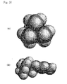
- Fig. 8 is diagrams which demonstrates minimum projection planes on which the molecular models of spiro-(1,1')bipyrrolidinium and triethylmethylammonium are projected, with minimum areas, perpendicularly to the sheet plane.
- Fig. 8(A) shows spiro-(1,1')bipyrrolidinium
- Fig. 8 (B) shows triethylmethylammonium.
- Fig. 9 is diagrams which demonstrates maximum projection planes on which the the molecular models of spiro-(1,1')bipyrrolidinium and triethylmethylammonium are projected, with maximum areas, perpendicularly to the sheet plane.
- Fig. 8(A) shows spiro-(1,1')bipyrrolidinium
- Fig. 8 (B) shows triethylmethylammonium.
- Fig. 9 is diagrams which demonstrates maximum projection planes on which the the molecular models of
- the molecular orbital calculation was conducted with using Mopac ver. 2.6 and specifying PM3 as the Hamiltonian. From these results, in the case of a molecule having a minimum projection area of an interatomic distance, excluding the spread of electron clouds, of 0.7 nm or less, it is assumed that ions will be adsorbed due to disorder of the crystal in the surface of graphite, so that a capacitance will be developed.
- Fig. 10 is a diagram which illustrates a molecular model of trimethylhexylammonium: Fig. 10 (A) shows a diagram viewing a minimum projection plane on which the area projected perpendicularly to the sheet plane is minimum; and Fig. 10 (B) shows a diagram viewing the maximum projection plane.
- Trimethylhexylammonium is of a greater solubility than tetramethylammonium and therefore is a desirable electrolytic solution. It is a substance resulting from replacement of part of the chemical structure of tetramethylammonium, which is an equilateral triangular pyramid with each edge 0.424 nm long. Thus, a substance resulting from replacement of one of the methyl groups of tetramethylammonium by an alkyl group having from 2 to 10 carbon atoms is effective.
- Fig. 11 is a diagram which illustrates a molecular model of ethylmethylimidazolium: Fig. 11 (A) shows a diagram viewing a minimum projection plane of ethylmethylimidazolium; and Fig. 11 (B) shows the maximum projection plane. Although the steric interatomic distance of the minimum projection plane of ethylmethylimidazolium is as small as 0.3005 nm, it is assumed that it can not be used because it will decompose at or below the potential where adsorption occurs.
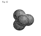
- Fig. 12 is a diagram which illustrates a molecular model of a BF 4 anion.
- a carbon electrode of the present invention for the positive electrode side and a polarizable carbon electrode made of activated carbon or nonporous carbon for the negative electrode side when the electrostatic capacitances of the electrodes of the positive electrode side and the negative electrode side were measured individually and the change in combined capacitance with increase in the volume of the negative electrode side was measured, the increase in capacitance stopped when the activated carbon electrode was increased to 5 times the graphite electrode in test cells 4-1 to 7-4. For nonporous electrodes, the capacitance did not increase any more when it was increased to 3 times the graphite electrode.
- the single electrode capacitance, under the same measurement conditions, of an activated carbon electrode used for the negative electrode of the present invention was about 50 F/g and the single electrode capacitance of a nonporous electrode was about 80 F/g. From this, it is assumed that when the same electrolytic solution is used, the single electrode capacitance in the case of using a graphite electrode for the positive electrode will be very high as about 240 to 250 F/g. Also when a graphite electrode was used as a negative electrode and a polarizable carbon electrode made of activated carbon or nonporous carbon was used in the positive electrode side, results similar to those mentioned above were obtained as shown in test cells 8-1 to 9-4.
- a graphite electrode of the present invention when used in combination with such activated carbon and a nonporous electrode, it is possible to reduce the volume of the graphite electrode, which has a smaller capacitance per unit volume in comparison to use of only activated carbon or nonporous electrode. It, therefore, is possible to obtain an electric double layer capacitor having a volume energy density larger than those of electric double layer capacitors having only an electrode of activated carbon or nonporous carbon.
- a cycle test was carried out in order to prove the durability of an electric double layer capacitor using the graphite. Charging and discharging were repeated using a charging/discharging current of 20 mA at 25°C and a terminal voltage of 3.5 V and the rate of change from an initial capacitance was measured.
- Cells illustrated in Fig. 2 were used in experiments and the experiments were conducted using the constitution shown as cell No. 1-1 in Table 2. As shown by numbers 11 and 15 in Fig. 2, aluminum is used for the collecting electrodes of the cell.
- Example 1-graphite electrode 1 graphite electrodes different in electrode density was prepared by changing the electrode molding pressure. These were assembled into cells with a constitution the same as that of cell 1-1 in Table 2. Then, a charging current was applied with a constant current of 5 mA, and at arrival at 3.2 V, switch to a constant voltage was made. Following the charging for 2 hours in total, discharging was conducted at 5 mA to 2 V and the electrostatic capacitance and resistance of the test cell were measured. The results are shown in Table 4.
- the electrode density in the graphite electrode at a large current is from 0.6 to 1.5 g/CC and preferably about from 0.7 to 1.4 g/CC. At a small electric power of 0.5 mA, it can be used over 1.6 g/cc.
- the electrode density of the activated carbon or nonporous electrode is from 0.6 to 1.0 g/CC, and preferably about from 0.7 to 0.9 g/CC.
- the present invention uses graphite whose voltage curve has an inflection point at the time of charging with a constant current and therefore a large electrostatic capacitance is developed in a charging process. It, therefore, is possible to provide an electric double layer capacitor which can work at a high speed and which has a large capacitance and a high withstanding voltage by use in combination, as counter electrodes, of a polarizable carbon electrode in an amount suitable for capacitance, such as a polarizable electrode made of graphite or activated carbon.
Applications Claiming Priority (3)
| Application Number | Priority Date | Filing Date | Title |
|---|---|---|---|
| JP2004067509 | 2004-03-10 | ||
| JP2004121985A JP4194044B2 (ja) | 2003-12-05 | 2004-04-16 | 正極及び負極に黒鉛を用いた電気二重層キャパシタ |
| PCT/JP2005/000765 WO2005088658A1 (fr) | 2004-03-10 | 2005-01-21 | Élément de stockage d’énergie et condensateur double couche électrique |
Publications (1)
| Publication Number | Publication Date |
|---|---|
| EP1727166A1 true EP1727166A1 (fr) | 2006-11-29 |
Family
ID=34975841
Family Applications (1)
| Application Number | Title | Priority Date | Filing Date |
|---|---|---|---|
| EP05703986A Withdrawn EP1727166A1 (fr) | 2004-03-10 | 2005-01-21 | Element de stockage d'energie et condensateur double couche electrique |
Country Status (4)
| Country | Link |
|---|---|
| US (1) | US7626804B2 (fr) |
| EP (1) | EP1727166A1 (fr) |
| KR (1) | KR20070005640A (fr) |
| WO (1) | WO2005088658A1 (fr) |
Cited By (2)
| Publication number | Priority date | Publication date | Assignee | Title |
|---|---|---|---|---|
| EP1770727A1 (fr) * | 2005-08-05 | 2007-04-04 | Power Systems Co., Ltd. | Procede pour activation electrique des condensateurs electriques a double couche |
| US9620820B2 (en) | 2012-10-09 | 2017-04-11 | Semiconductor Energy Laboratory Co., Ltd. | Power storage device |
Families Citing this family (32)
| Publication number | Priority date | Publication date | Assignee | Title |
|---|---|---|---|---|
| US7352558B2 (en) | 2003-07-09 | 2008-04-01 | Maxwell Technologies, Inc. | Dry particle based capacitor and methods of making same |
| US7791860B2 (en) | 2003-07-09 | 2010-09-07 | Maxwell Technologies, Inc. | Particle based electrodes and methods of making same |
| US7920371B2 (en) | 2003-09-12 | 2011-04-05 | Maxwell Technologies, Inc. | Electrical energy storage devices with separator between electrodes and methods for fabricating the devices |
| US7090946B2 (en) | 2004-02-19 | 2006-08-15 | Maxwell Technologies, Inc. | Composite electrode and method for fabricating same |
| US7440258B2 (en) | 2005-03-14 | 2008-10-21 | Maxwell Technologies, Inc. | Thermal interconnects for coupling energy storage devices |
| JP2006261599A (ja) * | 2005-03-18 | 2006-09-28 | Japan Gore Tex Inc | 電気二重層キャパシタの製造方法 |
| TWI367511B (en) * | 2005-06-10 | 2012-07-01 | Japan Gore Tex Inc | Electrode for electric double layer capacitor and electric double layer capacitor |
| JP3936374B2 (ja) * | 2005-10-18 | 2007-06-27 | 株式会社パワーシステム | 電気二重層キャパシタの充放電制御装置 |
| US20090197168A1 (en) * | 2005-11-04 | 2009-08-06 | Tetsuo Nishida | Storage element |
| JP3920310B1 (ja) * | 2006-03-10 | 2007-05-30 | 株式会社パワーシステム | 電気二重層キャパシタ用正電極及び電気二重層キャパシタ |
| JP4878881B2 (ja) * | 2006-03-17 | 2012-02-15 | 日本ゴア株式会社 | 電気二重層キャパシタ用電極および電気二重層キャパシタ |
| WO2008061212A2 (fr) | 2006-11-15 | 2008-05-22 | Energ2, Inc. | Dispositif capacitif a double couche électrique |
| US20080201925A1 (en) | 2007-02-28 | 2008-08-28 | Maxwell Technologies, Inc. | Ultracapacitor electrode with controlled sulfur content |
| KR101499602B1 (ko) | 2009-05-26 | 2015-03-09 | 가부시키가이샤 인큐베이션 얼라이언스 | 탄소 재료 및 그 제조 방법 |
| WO2011003033A1 (fr) | 2009-07-01 | 2011-01-06 | Energ2, Inc. | Matériaux en carbone synthétique ultra-pur |
| CN103261090A (zh) | 2010-09-30 | 2013-08-21 | 艾纳G2技术公司 | 储能颗粒的增强式装填 |
| US20120262127A1 (en) | 2011-04-15 | 2012-10-18 | Energ2 Technologies, Inc. | Flow ultracapacitor |
| CN103947017B (zh) | 2011-06-03 | 2017-11-17 | 巴斯福股份公司 | 用于混合能量存储装置中的碳‑铅共混物 |
| WO2013120011A1 (fr) | 2012-02-09 | 2013-08-15 | Energ2 Technologies, Inc. | Préparation de résines polymères et de matériaux carbonés |
| CN105190948B (zh) | 2013-03-14 | 2019-04-26 | 14族科技公司 | 包含锂合金化的电化学改性剂的复合碳材料 |
| CN105378870B (zh) | 2013-07-02 | 2018-02-13 | 大塚化学株式会社 | 双电层电容器用非水电解液 |
| US10195583B2 (en) | 2013-11-05 | 2019-02-05 | Group 14 Technologies, Inc. | Carbon-based compositions with highly efficient volumetric gas sorption |
| US10590277B2 (en) | 2014-03-14 | 2020-03-17 | Group14 Technologies, Inc. | Methods for sol-gel polymerization in absence of solvent and creation of tunable carbon structure from same |
| US10014704B2 (en) * | 2015-01-30 | 2018-07-03 | Corning Incorporated | Integrated energy and power device |
| US10763501B2 (en) | 2015-08-14 | 2020-09-01 | Group14 Technologies, Inc. | Nano-featured porous silicon materials |
| EP3836261A1 (fr) | 2015-08-28 | 2021-06-16 | Group14 Technologies, Inc. | Nouveaux matériaux à insertion extrêmement durable de lithium et leurs procédés de fabrication |
| JP7012660B2 (ja) | 2016-04-01 | 2022-02-14 | ノームズ テクノロジーズ インコーポレイテッド | リン含有修飾イオン性液体 |
| US11611071B2 (en) | 2017-03-09 | 2023-03-21 | Group14 Technologies, Inc. | Decomposition of silicon-containing precursors on porous scaffold materials |
| JP7296893B2 (ja) | 2017-07-17 | 2023-06-23 | ノームズ テクノロジーズ インコーポレイテッド | リン含有電解質 |
| US11639292B2 (en) | 2020-08-18 | 2023-05-02 | Group14 Technologies, Inc. | Particulate composite materials |
| US11174167B1 (en) | 2020-08-18 | 2021-11-16 | Group14 Technologies, Inc. | Silicon carbon composites comprising ultra low Z |
| US11335903B2 (en) | 2020-08-18 | 2022-05-17 | Group14 Technologies, Inc. | Highly efficient manufacturing of silicon-carbon composites materials comprising ultra low z |
Family Cites Families (13)
| Publication number | Priority date | Publication date | Assignee | Title |
|---|---|---|---|---|
| JPS60182670A (ja) * | 1984-02-28 | 1985-09-18 | Toray Ind Inc | 充放電可能な電池 |
| JPS63215031A (ja) | 1987-03-04 | 1988-09-07 | 松下電器産業株式会社 | 電気二重層コンデンサ |
| JP2701876B2 (ja) * | 1988-08-19 | 1998-01-21 | 日本ケミコン株式会社 | 電解コンデンサ用電解液 |
| JPH05139712A (ja) * | 1991-11-19 | 1993-06-08 | Koa Oil Co Ltd | 導電性多孔質炭素材の製造方法 |
| JPH09320906A (ja) * | 1996-05-27 | 1997-12-12 | Honda Motor Co Ltd | 電気二重層コンデンサ電極用活性炭並びにその製造方法および電気二重層コンデンサ電極 |
| JP2000077273A (ja) | 1998-09-03 | 2000-03-14 | Ngk Insulators Ltd | 電気二重層コンデンサ及びその製造方法 |
| JP2004003097A (ja) | 1999-03-25 | 2004-01-08 | Showa Denko Kk | 炭素繊維、その製造方法及び電池用電極 |
| TW524904B (en) * | 1999-03-25 | 2003-03-21 | Showa Denko Kk | Carbon fiber, method for producing same and electrodes for electric cells |
| JP2001180923A (ja) | 1999-12-28 | 2001-07-03 | Petoca Ltd | 活性炭、その製造方法、それを用いた電極及びそれを用いた電気二重層キャパシタ |
| JP2001236960A (ja) * | 2000-02-22 | 2001-08-31 | Asahi Glass Co Ltd | 二次電源の製造方法 |
| JP2002151364A (ja) | 2000-11-09 | 2002-05-24 | Asahi Glass Co Ltd | 電気二重層キャパシタ及びその製造方法 |
| EP1324358A3 (fr) * | 2001-12-11 | 2003-12-17 | Asahi Glass Co., Ltd. | Condensateur électrique à double couche |
| US6757154B2 (en) * | 2001-12-13 | 2004-06-29 | Advanced Energy Technology Inc. | Double-layer capacitor components and method for preparing them |
-
2005
- 2005-01-21 US US10/592,047 patent/US7626804B2/en not_active Expired - Fee Related
- 2005-01-21 WO PCT/JP2005/000765 patent/WO2005088658A1/fr active Application Filing
- 2005-01-21 EP EP05703986A patent/EP1727166A1/fr not_active Withdrawn
- 2005-01-21 KR KR1020067019649A patent/KR20070005640A/ko not_active Application Discontinuation
Non-Patent Citations (1)
| Title |
|---|
| See references of WO2005088658A1 * |
Cited By (4)
| Publication number | Priority date | Publication date | Assignee | Title |
|---|---|---|---|---|
| EP1770727A1 (fr) * | 2005-08-05 | 2007-04-04 | Power Systems Co., Ltd. | Procede pour activation electrique des condensateurs electriques a double couche |
| US9620820B2 (en) | 2012-10-09 | 2017-04-11 | Semiconductor Energy Laboratory Co., Ltd. | Power storage device |
| US9847555B2 (en) | 2012-10-09 | 2017-12-19 | Semiconductor Energy Laboratory Co., Ltd. | Power storage device |
| US10128541B2 (en) | 2012-10-09 | 2018-11-13 | Semiconductor Energy Laboratory Co., Ltd. | Power storage device |
Also Published As
| Publication number | Publication date |
|---|---|
| WO2005088658A1 (fr) | 2005-09-22 |
| US7626804B2 (en) | 2009-12-01 |
| US20070201185A1 (en) | 2007-08-30 |
| KR20070005640A (ko) | 2007-01-10 |
Similar Documents
| Publication | Publication Date | Title |
|---|---|---|
| US7626804B2 (en) | Power storage element and electric double layer capacitor | |
| Väli et al. | Synthesis and characterization of D-glucose derived nanospheric hard carbon negative electrodes for lithium-and sodium-ion batteries | |
| EP2998973B1 (fr) | Condensateur et son procédé de charge-décharge | |
| JP4888667B2 (ja) | 蓄電デバイスおよび蓄電システム | |
| US8900754B2 (en) | Electrode, and lithium ion secondary battery, electric double layer capacitor and fuel cell using the same | |
| EP3392897B1 (fr) | Élément de stockage d'énergie de type à lithium non aqueux | |
| US20120255858A1 (en) | Activated carbon for electrochemical element and electrochemical element using the same | |
| JP2005294780A (ja) | 蓄電要素及び電気二重層キャパシタ | |
| US7286334B2 (en) | Electric double layer capacitor | |
| EP2306476A1 (fr) | Carbone activé pour élément électrochimique et élément électrochimique associé | |
| JP2001185459A (ja) | 電気化学キャパシタ | |
| US20070223178A1 (en) | Electric double layer capacitor | |
| US11637286B2 (en) | Carbonaceous material for negative electrode active material for non-aqueous electrolyte secondary batteries, non-aqueous electrolyte secondary battery negative electrode, non-aqueous electrolyte secondary battery, and production method of carbonaceous material | |
| JP2007305625A (ja) | 疑似容量キャパシタ | |
| JP2008205485A (ja) | 黒鉛を用いた電気二重層キャパシタ用正電極及び電気二重層キャパシタ | |
| JP2007305626A (ja) | 蓄電システム | |
| JP4081125B2 (ja) | 電気二重層キャパシタ用正電極及び電気二重層キャパシタ | |
| JP3920310B1 (ja) | 電気二重層キャパシタ用正電極及び電気二重層キャパシタ | |
| Priyadharsini et al. | Nano-sheet-like KNiPO4 as a positive electrode material for aqueous hybrid supercapacitors | |
| JP2010254537A (ja) | 炭素質材料、この炭素質材料を有する蓄電装置、及び炭素質材料の製造方法 | |
| US20060245143A1 (en) | Positive electrode for electric double layer capacitors and method for the production thereof | |
| JP4194052B2 (ja) | 正電極に黒鉛を用いた電気二重層キャパシタ | |
| JP4916632B2 (ja) | 気相法炭素繊維およびその用途 | |
| JP4066506B2 (ja) | 炭素質物質の製造方法。 | |
| WO2024024956A1 (fr) | Dispositif electrochimique |
Legal Events
| Date | Code | Title | Description |
|---|---|---|---|
| PUAI | Public reference made under article 153(3) epc to a published international application that has entered the european phase |
Free format text: ORIGINAL CODE: 0009012 |
|
| 17P | Request for examination filed |
Effective date: 20060824 |
|
| AK | Designated contracting states |
Kind code of ref document: A1 Designated state(s): AT BE BG CH CY CZ DE DK EE ES FI FR GB GR HU IE IS IT LI LT LU MC NL PL PT RO SE SI SK TR |
|
| AX | Request for extension of the european patent |
Extension state: AL BA HR LV MK YU |
|
| RAP1 | Party data changed (applicant data changed or rights of an application transferred) |
Owner name: POWER SYSTEMS CO., LTD. Owner name: YOSHIO, MASAKI |
|
| STAA | Information on the status of an ep patent application or granted ep patent |
Free format text: STATUS: THE APPLICATION IS DEEMED TO BE WITHDRAWN |
|
| 18D | Application deemed to be withdrawn |
Effective date: 20100202 |