EP1726751A1 - Schließzylinder - Google Patents
Schließzylinder Download PDFInfo
- Publication number
- EP1726751A1 EP1726751A1 EP06110594A EP06110594A EP1726751A1 EP 1726751 A1 EP1726751 A1 EP 1726751A1 EP 06110594 A EP06110594 A EP 06110594A EP 06110594 A EP06110594 A EP 06110594A EP 1726751 A1 EP1726751 A1 EP 1726751A1
- Authority
- EP
- European Patent Office
- Prior art keywords
- core
- lock cylinder
- locking
- housing
- Prior art date
- Legal status (The legal status is an assumption and is not a legal conclusion. Google has not performed a legal analysis and makes no representation as to the accuracy of the status listed.)
- Granted
Links
Images

Classifications
-
- E—FIXED CONSTRUCTIONS
- E05—LOCKS; KEYS; WINDOW OR DOOR FITTINGS; SAFES
- E05B—LOCKS; ACCESSORIES THEREFOR; HANDCUFFS
- E05B47/00—Operating or controlling locks or other fastening devices by electric or magnetic means
- E05B47/06—Controlling mechanically-operated bolts by electro-magnetically-operated detents
- E05B47/0611—Cylinder locks with electromagnetic control
- E05B47/0619—Cylinder locks with electromagnetic control by blocking the rotor
- E05B47/0626—Cylinder locks with electromagnetic control by blocking the rotor radially
- E05B47/063—Cylinder locks with electromagnetic control by blocking the rotor radially with a rectilinearly moveable blocking element
-
- E—FIXED CONSTRUCTIONS
- E05—LOCKS; KEYS; WINDOW OR DOOR FITTINGS; SAFES
- E05B—LOCKS; ACCESSORIES THEREFOR; HANDCUFFS
- E05B47/00—Operating or controlling locks or other fastening devices by electric or magnetic means
- E05B47/0001—Operating or controlling locks or other fastening devices by electric or magnetic means with electric actuators; Constructional features thereof
- E05B47/0002—Operating or controlling locks or other fastening devices by electric or magnetic means with electric actuators; Constructional features thereof with electromagnets
- E05B47/0003—Operating or controlling locks or other fastening devices by electric or magnetic means with electric actuators; Constructional features thereof with electromagnets having a movable core
- E05B47/0004—Operating or controlling locks or other fastening devices by electric or magnetic means with electric actuators; Constructional features thereof with electromagnets having a movable core said core being linearly movable
Definitions
- the invention relates to a lock cylinder with a rotatable core in a housing and with an electromagnetically activatable locking mechanism for selectively blocking or releasing the movement of the core, wherein the housing is made of non-magnetic material.
- Such lock cylinders are commonly used in today's electronic locking systems and are for example from the DE 199 01 838 A1 known.
- This lock cylinder has arranged in a usually made of brass housing, electromagnetic actuator which holds a biased by a spring element in the direction of a pocket in the core locking bolt or releases its movement.
- the electromagnetically activatable locking mechanism can be controlled for example by a numeric code or a transponder. If the electromagnetic actuator holds the locking bar, the core can be rotated relative to the housing and thus unlock the lock cylinder. In the absence of a locking authorization of the electromagnetic actuator releases the movement of the locking bar, so that it is pressed by the force of the spring element in the pocket in the core and prevents rotation of the core relative to the housing.
- the electromagnetic actuator may possibly be magnetized such that the locking bar is held outside the pocket of the core without activation of the electromagnetically activatable locking mechanism.
- the invention is based on the problem, the lock cylinder of the type mentioned in such a way that its unlocking is reliably avoided even with a strong external magnetic field.
- the housing or the core has a locking pocket which is open in the intended mounting direction for essentially flush receiving a magnetizable material control element
- the respective other component has a control pocket open towards the bottom
- Recording the control and in the direction of movement of the core next to the control pocket has a downwardly open retaining pocket and that in the retaining pocket a blocking element is arranged from non-magnetizable material and that the locking pocket has dimensions for only partially receiving the blocking element.
- a strong magnetic field acting on the lock cylinder according to the invention leads to the movement of the control element out of the lock pocket into the control pocket.
- the lock pocket is empty.
- the blocking element is moved over the locking pocket, whereupon the blocking element falls by gravity into the locking pocket. Since the locking pocket can only partially absorb the blocking element because of its dimensions, the blocking element lies in the parting plane between the housing and the core and blocks the further movement of the core. In order for a release of the lock cylinder according to the invention is reliably avoided even with a strong external magnetic field. Without presence of an external magnetic field that closes Control the lock pocket flush so that the lock member slides over the lock pocket as the core moves.
- the barrier pocket could be located on top of the core.
- this requires the arrangement of the holding pockets with the blocking element above the core in the housing and thus a large wall thickness of the housing above the core.
- the housing of the lock cylinder according to the invention requires only a small wall thickness when the lock pocket in the housing and the retaining pocket are arranged in the core.
- the structural complexity for blocking the core after an attempted unlocking with a magnet can be kept particularly low according to another advantageous embodiment of the invention, when a single retaining pocket is arranged seen from the lock pocket on the opposite side of the core.
- Locking the movement of the core can be ensured according to an advantageous development of the invention in both directions of movement already with a short movement of the core, when the control pocket between two holding pockets, each with a blocking element is arranged.
- the lock cylinder according to the invention contributes to a spherical shape of the control element and / or the blocking element. Furthermore, this design allows a low-friction rolling of the control element and / or the blocking element during the movement of the core.
- a reliable locking of the core after a Unlock attempt of the lock cylinder according to the invention can be easily achieved when one of the control pocket pioneering edge of the holding pocket inclined to the parting plane between the core and housing expires.
- the core can simply be moved backwards into the starting position by return movement if a lateral edge of the holding pocket has a lifting edge engaging behind the locking element located in the lock pocket. This prevents that the lock cylinder according to the invention is destroyed by the action of a magnetic field.
- the combination of the lifting edge on one flank with the inclination of the other flank of the holding bag can be ensured that the core is blocked in one direction and movable in the other direction.
- a reliable wedging of the blocking element in the parting plane between the housing and the core can be ensured according to a further advantageous embodiment of the invention, when the locking pocket on the parting plane between the housing and core has inclined flanks. Furthermore, the control element is reliably moved out of the locking pocket by the external magnetic field, since it is attracted by the magnetic field either attracted to the.
- the control can be removed according to another advantageous embodiment of the invention even at low magnetic field strengths from the locking pocket when the housing or the core has an insert made of magnetizable material and when the insert is guided to the control pocket.
- a separately to be mounted insert of magnetizable material can be avoided according to another advantageous embodiment of the invention, if the core is made at least in the region of the control pocket of a magnetizable material.
- the movement of the blocking element is usually by gravity.
- the blocking element can be moved independently of gravity according to another advantageous embodiment of the invention, when the blocking element is biased by a spring element in the direction of the parting plane between the housing and core.
- Figure 1 shows a lock cylinder with a rotatable in a housing 1 core 2 in a longitudinal section.
- the locking cylinder has an electromagnetically activatable locking mechanism 3 with an axially displaceably arranged in the housing 1 and biased by a spring element 4 in the direction of the core 2 locking bolt 5.
- the locking mechanism 3 has an electromagnet 6, which pressed the locking latch 5 in one in the housing 1 To hold a position.
- the locking bar 5 is partially in a recess 7 of the core 2 and thus blocks the movement of the core 2 relative to the housing 1. This indicates the basic position of the lock cylinder.
- the locking bar 5 can be pressed, for example, via a key inserted into a closing channel 8 of the core 2 and a subsequent rotation of the core 2 into the housing 1.
- the electromagnet 6 holds the locking bolt 5 in a completely located in the housing 1 position and therefore allows the rotation of the core 2 relative to the Housing 1.
- the lock cylinder has a lying in a lock pocket 9 control 10.
- the control element 10 is opposite to a control pocket 11 in the core 2.
- the control pocket 11 is arranged in an insert 12 of the core 2.
- the control element 10 and the insert 12 are made of a magnetizable material, while the housing 1 is made of brass, for example.
- Figure 2 shows an enlarged cross section of the lock cylinder of Figure 1 along the line II - II in the plane of the control element 10.
- the control element 10 is flush in the locking pocket 9.
- On both sides of the control pocket 11 are holding pockets 13, 13 'for each locking element 14, 14 'arranged.
- the blocking elements 14, 14 ' are made of a non-magnetic material.
- the locking pocket 9 has on the parting plane between the housing 1 and core 2 inclined flanks 15.
- the magnetizable control element 10 When a strong magnetic field acts on the lock cylinder, the magnetizable control element 10 is attracted by the magnetizable insert 12 and rolls along the flanks 15 of the locking pocket 9 in the control pocket 11 of the core 2. Subsequently, the core 2 is rotated as shown in FIG In the direction of the parting plane between the housing 1 and core 2 inclined flanks 16 of the corresponding holding pocket 13 then lead to the blocking element 14 in the parting plane between the housing 1 and core 2 is trapped and prevents the further movement of the core 2.
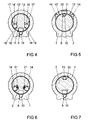
- Figure 4 shows a further embodiment of the lock cylinder according to the invention in cross section, which differs from that of Figures 2 and 3, that of the control pocket 11 pioneering edges 17, 17 'of the holding pockets 13, 13' inclined to the parting plane between the core 2 and housing 1 expire.
- the control pocket 11 facing flanks 18, 18 'of the holding pockets 13, 13' each have a lifting edge 19, 19 'on.
- the core 2 is made in the region of the control pocket 11 of a magnetizable material. When the control member 10 is in the control pocket 11 and the core 2 is rotated, the core 2 blocks in a further rotation in which the inclined flank 17 of the respective holding pocket 13 presses against the blocking element 14.
- the core 2 can be moved back into the starting position shown in FIG. 4 even after an action of a strong magnetic field.
- Figure 5 shows a further embodiment of the lock cylinder according to the invention in cross section, which differs from that of Figure 2 only in that the locking pocket 9 in the core 2 and two locking elements 14 are located in the housing 1 holding pockets 13, 13 'are arranged. Therefore, the control element 10 in the core 2 and a control pocket 11 in the housing 1 is arranged. Likewise, an insert 20 of magnetizable material in the housing 1 is arranged. The function of this embodiment is therefore the same as in the embodiment of Figures 2 and 3.
- FIG. 6 shows a further embodiment of the lock cylinder from FIG. 1 in cross section, which differs from that of FIG. 4 in that the locking elements 14, 14 'are biased by spring elements 21, 21' in the direction of the parting plane between housing 1 and core 2.
- spring elements 21, 21 ' support the force acting on the locking elements 14, 14' gravity when the locking pocket 9 is empty and the core 2 is slightly rotated.
- An embodiment of the lock cylinder according to the invention shown in Figure 7 of Figure 1 has a single, arranged in the core 2 holding pocket 22 for receiving a single blocking element 23.
- the holding pocket 22 is arranged on the side of the core 2 opposite the control pocket 9. If the control element 10 is removed from the blocking pocket 9 by a magnetic field, the core 2 can be rotated by 180 ° in both directions until the blocking element 23 falls into the blocking pocket 9.
Landscapes
- Physics & Mathematics (AREA)
- Electromagnetism (AREA)
- Lock And Its Accessories (AREA)
- Valve Device For Special Equipments (AREA)
- Fluid-Damping Devices (AREA)
- Pens And Brushes (AREA)
- Purses, Travelling Bags, Baskets, Or Suitcases (AREA)
Abstract
Description
- Die Erfindung betrifft einen Schließzylinder mit einem in einem Gehäuse drehbaren Kern und mit einem elektromagnetisch aktivierbaren Sperrmechanismus zur wahlweisen Blockierung oder Freigabe der Bewegung des Kerns, wobei das Gehäuse aus unmagnetischem Material gefertigt ist.
- Solche Schließzylinder werden in heutigen elektronischen Schließanlagen häufig eingesetzt und sind beispielsweise aus der
DE 199 01 838 A1 bekannt. Dieser Schließzylinder hat einen in einem meist aus Messing gefertigten Gehäuse angeordneten, elektromagnetischen Aktor, welcher einen von einem Federelement in Richtung einer Tasche im Kern vorgespannten Sperrriegel hält oder dessen Bewegung freigibt. Der elektromagnetisch aktivierbare Sperrmechanismus kann beispielsweise von einem Zahlencode oder einem Transponder angesteuert werden. Wenn der elektromagnetische Aktor den Sperrriegel hält, lässt sich der Kern gegenüber dem Gehäuse verdrehen und damit der Schließzylinder entriegeln. Bei fehlender Schließberechtigung gibt der elektromagnetische Aktor die Bewegung des Sperrriegels frei, so dass dieser von der Kraft des Federelementes in die Tasche im Kern gedrückt wird und eine Drehung des Kerns gegenüber dem Gehäuse verhindert. Wenn man jedoch ein starkes Magnetfeld an dem Sperrmechanismus anlegt, kann unter Umständen der elektromagnetische Aktor derart magnetisiert werden, dass der Sperrriegel ohne Ansteuerung des elektromagnetisch aktivierbaren Sperrmechanismus außerhalb der Tasche des Kerns gehalten wird. - Der Erfindung liegt das Problem zugrunde, den Schließzylinder der eingangs genannten Art so weiterzubilden, dass dessen Entriegelung auch mit einem starken äußeren Magnetfeld zuverlässig vermieden wird.
- Dieses Problem wird erfindungsgemäß dadurch gelöst, dass das Gehäuse oder der Kern eine in der vorgesehenen Montagerichtung nach oben offene Sperrtasche zur im Wesentlichen bündig abschließenden Aufnahme eines aus einem magnetisierbaren Material gefertigten Steuerelementes hat, dass das jeweils andere Bauteil eine nach unten hin offene Steuertasche zur vollständigen Aufnahme des Steuerelementes und in Bewegungsrichtung des Kerns neben der Steuertasche eine nach unten hin offene Haltetasche aufweist und dass in der Haltetasche ein Sperrelement aus nicht magnetisierbarem Material angeordnet ist und dass die Sperrtasche Abmessungen zur ausschließlich teilweisen Aufnahme des Sperrelementes aufweist.
- Durch diese Gestaltung führt ein starkes, auf den erfindungsgemäßen Schließzylinder einwirkendes Magnetfeld zur Bewegung des Steuerelementes aus der Sperrtasche heraus in die Steuertasche. Damit ist die Sperrtasche leer. Bei einer folgenden Bewegung des Kerns wird das Sperrelement über die Sperrtasche bewegt, worauf das Sperrelement durch die Schwerkraft in die Sperrtasche fällt. Da die Sperrtasche wegen ihrer Abmessungen das Sperrelement nur teilweise aufnehmen kann, liegt das Sperrelement in der Trennebene zwischen Gehäuse und Kern und blockiert die weitere Bewegung des Kerns. Damit wird eine Entriegelung des erfindungsgemäßen Schließzylinders auch mit einem starken äußeren Magnetfeld zuverlässig vermieden. Ohne Vorhandensein eines äußeren Magnetfeldes schließt das Steuerelement die Sperrtasche bündig ab, so dass das Sperrelement bei der Bewegung des Kerns über die Sperrtasche hinweg gleitet.
- Die Sperrtasche könnte beispielsweise auf der Oberseite des Kerns angeordnet sein. Dies erfordert jedoch die Anordnung der Haltetaschen mit dem Sperrelement oberhalb des Kerns in dem Gehäuse und damit eine große Wandstärke des Gehäuses oberhalb des Kerns. Das Gehäuse des erfindungsgemäßen Schließzylinders erfordert jedoch nur eine geringe Wandstärke, wenn die Sperrtasche in dem Gehäuse und die Haltetasche in dem Kern angeordnet sind.
- Der bauliche Aufwand zur Blockierung des Kerns nach einem versuchten Entriegeln mit einem Magneten lässt sich gemäß einer anderen vorteilhaften Weiterbildung der Erfindung besonders gering halten, wenn eine einzige Haltetasche von der Sperrtasche aus gesehen auf der gegenüberliegenden Seite des Kerns angeordnet ist.
- Ein Sperren der Bewegung des Kerns lässt sich gemäß einer vorteilhaften Weiterbildung der Erfindung in beide Bewegungsrichtungen bereits bei einer kurzen Bewegung des Kerns sicherstellen, wenn die Steuertasche zwischen zwei Haltetaschen mit jeweils einem Sperrelement angeordnet ist.
- Zur weiteren Verringerung der Fertigungskosten des erfindungsgemäßen Schließzylinders trägt eine Kugelform des Steuerelementes und/oder des Sperrelementes bei. Weiterhin ermöglicht diese Gestaltung ein reibungsarmes Abrollen des Steuerelementes und/oder des Sperrelementes bei der Bewegung des Kerns.
- Eine zuverlässige Blockierung des Kerns nach einem Entriegelungsversuch des erfindungsgemäßen Schließzylinders lässt sich einfach erreichen, wenn eine von der Steuertasche wegweisende Flanke der Haltetasche geneigt auf die Trennebene zwischen Kern und Gehäuse ausläuft.
- Der Kern lässt sich nach einem Entriegelungsversuch des erfindungsgemäßen Schließzylinders durch Rückbewegung einfach in die Ausgangslage zurück bewegen, wenn eine seitliche Flanke der Haltetasche eine das in der Sperrtasche befindliche Sperrelement hintergreifende Hebekante aufweist. Hierdurch wird verhindert, dass der erfindungsgemäße Schließzylinder durch die Einwirkung eines Magnetfeldes zerstört wird. Insbesondere durch die Kombination der Hebekante an der einen Flanke mit der Neigung der anderen Flanke der Haltetasche lässt sich sicherstellen, dass der Kern in der einen Richtung blockiert und in der anderen Richtung beweglich ist.
- Ein zuverlässiges Verkeilen des Sperrelementes in der Trennebene zwischen Gehäuse und Kern lässt sich gemäß einer weiteren vorteilhaften Weiterbildung der Erfindung sicherstellen, wenn die Sperrtasche auf die Trennebene zwischen Gehäuse und Kern geneigte Flanken hat. Weiterhin wird das Steuerelement durch das äußere Magnetfeld zuverlässig aus der Sperrtasche heraus bewegt, da es von dem Magnetfeld entweder angezogen der abgestoßen wird.
- Das Steuerelement lässt sich gemäß einer anderen vorteilhaften Weiterbildung der Erfindung bereits bei geringen magnetischen Feldstärken aus der Sperrtasche entfernen, wenn das Gehäuse oder der Kern einen Einsatz aus magnetisierbarem Material aufweist und wenn der Einsatz bis zu der Steuertasche geführt ist.
- Ein separat zu montierender Einsatz aus magnetisierbarem Material lässt sich gemäß einer anderen vorteilhaften Weiterbildung der Erfindung vermeiden, wenn der Kern zumindest im Bereich der Steuertasche aus einem magnetisierbaren Material gefertigt ist.
- Die Bewegung des Sperrelementes erfolgt in der Regel durch die Schwerkraft. Das Sperrelement lässt sich jedoch gemäß einer anderen vorteilhaften Weiterbildung der Erfindung unabhängig von der Schwerkraft bewegen, wenn das Sperrelement von einem Federelement in Richtung der Trennebene zwischen Gehäuse und Kern vorgespannt ist.
- Die Erfindung lässt zahlreiche Ausführungsformen zu. Zur weiteren Verdeutlichung ihres Grundprinzips sind mehrere davon in der Zeichnung dargestellt und werden nachfolgend beschrieben. Diese zeigt in
- Fig. 1
- einen Längsschnitt eines erfindungsgemäßen Schließzylinders,
- Fig. 2
- einen Querschnitt durch den erfindungsgemäßen Schließzylinder aus Figur 1 entlang der Linie II - II,
- Fig. 3
- den erfindungsgemäßen Schließzylinder aus Figur 2 in einer Sperrstellung,
- Fig. 4
- einen Querschnitt durch eine weitere Ausführungsform des erfindungsgemäßen Schließzylinders,
- Fig. 5
- einen Querschnitt durch eine weitere Ausführungsform des erfindungsgemäßen Schließzylinders mit in einem Kern angeordnetem Steuerelement,
- Fig. 6
- einen Querschnitt durch eine weitere Ausführungsform des erfindungsgemäßen Schließzylinders mit von einem Federelement vorgespanntem Sperrelement,
- Fig. 7
- einen Querschnitt durch eine weitere Ausführungsform des erfindungsgemäßen Schließzylinders mit einem einzigen Sperrelement.
- Figur 1 zeigt einen Schließzylinder mit einem in einem Gehäuse 1 drehbaren Kern 2 in einem Längsschnitt. Der Schließzylinder hat einen elektromagnetisch aktivierbaren Sperrmechanismus 3 mit einem im Gehäuse 1 axial verschieblich angeordneten und von einem Federelement 4 in Richtung des Kerns 2 vorgespannten Sperrriegel 5. Weiterhin hat der Sperrmechanismus 3 einen Elektromagneten 6, welcher den Sperrriegel 5 in einer in das Gehäuse 1 eingedrückten Stellung zu halten vermag. In der dargestellten Stellung befindet sich der Sperrriegel 5 teilweise in einer Ausnehmung 7 des Kerns 2 und blockiert damit die Bewegung des Kerns 2 gegenüber dem Gehäuse 1. Dies kennzeichnet die Grundstellung des Schließzylinders. Der Sperrriegel 5 lässt sich beispielsweise über einen in einen Schließkanal 8 des Kerns 2 eingeführten Schlüssel und eine anschließende Drehung des Kerns 2 in das Gehäuse 1 drücken. Bei Vorliegen einer Schließberechtigung des Schlüssels hält der Elektromagnet 6 den Sperrriegel 5 in einer vollständig im Gehäuse 1 befindlichen Stellung und ermöglicht daher die Drehung des Kerns 2 gegenüber dem Gehäuse 1. Der Schließzylinder und die Funktion des Sperrmechanismus 3 sind ausführlich in der
DE 199 01 838 A1 beschrieben, so das zur Offenbarung der Funktion der Bauteile des Schließzylinders ausdrücklich auf diese Schrift verwiesen wird. - Weiterhin hat der Schließzylinder ein in einer Sperrtasche 9 liegendes Steuerelement 10. Das Steuerelement 10 steht einer Steuertasche 11 im Kern 2 gegenüber. Die Steuertasche 11 ist in einem Einsatz 12 des Kerns 2 angeordnet. Das Steuerelement 10 und der Einsatz 12 sind aus einem magnetisierbaren Material gefertigt, während das Gehäuse 1 beispielsweise aus Messing besteht. Figur 2 zeigt vergrößert einen Querschnitt des Schließzylinders aus Figur 1 entlang der Linie II - II in der Ebene des Steuerelementes 10. Das Steuerelement 10 liegt bündig in der Sperrtasche 9. Zu beiden Seiten der Steuertasche 11 sind Haltetaschen 13, 13' für jeweils ein Sperrelement 14, 14' angeordnet. Die Sperrelemente 14, 14' sind aus einem unmagnetischen Material gefertigt. Die Sperrtasche 9 weist auf die Trennebene zwischen Gehäuse 1 und Kern 2 geneigte Flanken 15 auf.
- Wenn ein starkes Magnetfeld auf den Schließzylinder einwirkt, wird das magnetisierbare Steuerelement 10 von dem magnetisierbaren Einsatz 12 angezogen und rollt entlang der Flanken 15 der Sperrtasche 9 in die Steuertasche 11 des Kerns 2. Wird anschließend der Kern 2 gedreht, wie es in Figur 3 dargestellt ist, bewegt sich das nächste Sperrelement 14 durch die Schwerkraft teilweise in die Sperrtasche 9. In Richtung der Trennebene zwischen Gehäuse 1 und Kern 2 geneigte Flanken 16 der entsprechenden Haltetasche 13 führen anschließend dazu, dass das Sperrelement 14 in der Trennebene zwischen Gehäuse 1 und Kern 2 eingeklemmt wird und die weitere Bewegung des Kerns 2 verhindert.
- Figur 4 zeigt eine weitere Ausführungsform des erfindungsgemäßen Schließzylinders im Querschnitt, welche sich von der aus den Figuren 2 und 3 unterscheidet, dass von der Steuertasche 11 wegweisende Flanken 17, 17' der Haltetaschen 13, 13' geneigt auf die Trennebene zwischen Kern 2 und Gehäuse 1 auslaufen. Der Steuertasche 11 zugewandte Flanken 18, 18' der Haltetaschen 13, 13' weisen jeweils eine Hebekante 19, 19' auf. Weiterhin ist der Kern 2 im Bereich der Steuertasche 11 aus einem magnetisierbaren Material gefertigt. Wenn sich das Steuerelement 10 in der Steuertasche 11 befindet und der Kern 2 gedreht wird, blockiert der Kern 2 bei einer weiteren Drehung, bei der die geneigte Flanke 17 der jeweiligen Haltetasche 13 gegen das Sperrelement 14 drückt. Wird jedoch die Hebekante 19 gegen das in der Sperrtasche 9 befindliche Sperrelement 14 bewegt, wird das Sperrelement 14 aus der Sperrtasche 9 herausgehoben. Damit kann im Gegensatz zu der Ausführungsform nach den Figuren 2 und 3 der Kern 2 auch nach einer Einwirkung eines starken Magnetfeldes wieder in die in Figur 4 dargestellte Ausgangslage zurück bewegt werden.
- Figur 5 zeigt eine weitere Ausführungsform des erfindungsgemäßen Schließzylinders im Querschnitt, welche sich von der aus Figur 2 nur dadurch unterscheidet, dass die Sperrtasche 9 im Kern 2 und zwei Sperrelemente 14 in im Gehäuse 1 befindlichen Haltetaschen 13, 13' angeordnet sind. Daher ist auch das Steuerelement 10 im Kern 2 und eine Steuertasche 11 im Gehäuse 1 angeordnet. Ebenso ist ein Einsatz 20 aus magnetisierbarem Material im Gehäuse 1 angeordnet. Die Funktion dieser Ausführungsform ist daher die gleiche wie bei der Ausführungsform nach den Figuren 2 und 3.
- Figur 6 zeigt eine weitere Ausführungsform des Schließzylinders aus Figur 1 im Querschnitt, welche sich von der aus Figur 4 dadurch unterscheidet, dass die Sperrelemente 14, 14' von Federelementen 21, 21' in Richtung der Trennebene zwischen Gehäuse 1 und Kern 2 vorgespannt sind. Diese Federelemente 21, 21' unterstützen die auf die Sperrelemente 14, 14' einwirkende Schwerkraft, wenn die Sperrtasche 9 leer ist und der Kern 2 geringfügig gedreht wird.
- Eine in Figur 7 dargestellte Ausführungsform des erfindungsgemäßen Schließzylinders aus Figur 1 weist eine einzige, im Kern 2 angeordnete Haltetasche 22 zur Aufnahme eines einzigen Sperrelementes 23 auf. Die Haltetasche 22 ist auf der der Steuertasche 9 gegenüberliegenden Seite des Kerns 2 angeordnet. Wird das Steuerelement 10 durch ein Magnetfeld aus der Sperrtasche 9 entfernt, lässt sich der Kern 2 in beide Richtungen um 180° drehen, bis das Sperrelement 23 in die Sperrtasche 9 fällt.
Claims (11)
- Schließzylinder mit einem in einem Gehäuse drehbaren Kern und mit einem elektromagnetisch aktivierbaren Sperrmechanismus zur wahlweisen Blockierung oder Freigabe der Bewegung des Kerns, wobei das Gehäuse aus unmagnetischem Material gefertigt ist, dadurch gekennzeichnet, dass das Gehäuse (1) oder der Kern (2) eine in der vorgesehenen Montagerichtung nach oben offene Sperrtasche (9) zur im Wesentlichen bündig abschließenden Aufnahme eines aus einem magnetisierbaren Material gefertigten Steuerelementes (10) hat, dass das jeweils andere Bauteil eine nach unten hin offene Steuertasche (11) zur vollständigen Aufnahme des Steuerelementes (10) und in Bewegungsrichtung des Kerns (2) neben der Steuertasche (11) eine nach unten hin offene Haltetasche (13, 22) aufweist und dass in der Haltetasche (13, 22) ein Sperrelement (14, 23) aus nicht magnetisierbarem Material angeordnet ist und dass die Sperrtasche (9) Abmessungen zur ausschließlich teilweisen Aufnahme des Sperrelementes (14, 23) aufweist.
- Schließzylinder nach Anspruch 1, dadurch gekennzeichnet, dass die Sperrtasche (9) in dem Gehäuse (1) und die Haltetasche (13, 22) in dem Kern (2) angeordnet sind.
- Schließzylinder nach Anspruch 1 oder 2, dadurch gekennzeichnet, dass eine einzige Haltetasche (22) von der Sperrtasche (9) aus gesehen auf der gegenüberliegenden Seite des Kerns (2) angeordnet ist.
- Schließzylinder nach Anspruch 1 oder 2, dadurch gekennzeichnet, dass die Steuertasche (11) zwischen zwei Haltetaschen (13, 13') mit jeweils einem Sperrelement (14, 14') angeordnet ist.
- Schließzylinder nach Anspruch 1 gekennzeichnet durch eine Kugelform des Steuerelementes (10) und/oder des Sperrelementes (14, 23).
- Schließzylinder nach Anspruch 3 oder 4, dadurch gekennzeichnet, dass eine von der Steuertasche (11) wegweisende Flanke (16, 17) der Haltetasche (13) geneigt auf die Trennebene zwischen Kern (2) und Gehäuse (1) ausläuft.
- Schließzylinder nach Anspruch 3 oder 4, dadurch gekennzeichnet, dass eine seitliche Flanke (18) der Haltetasche (13) eine das in der Sperrtasche (9) befindliche Sperrelement (14) hintergreifende Hebekante (19) aufweist.
- Schließzylinder nach Anspruch 3 oder 4, dadurch gekennzeichnet, dass die Sperrtasche (9) auf die Trennebene zwischen Gehäuse (1) und Kern (2) geneigte Flanken (15) hat.
- Schließzylinder nach einem der Ansprüche 1 bis 8, dadurch gekennzeichnet, dass das Gehäuse (1) oder der Kern (2) einen Einsatz (12, 20) aus magnetisierbarem Material aufweist und dass der Einsatz (12, 20) bis zu der Steuertasche (11) geführt ist.
- Schließzylinder nach einem der Ansprüche 1 bis 8, dadurch gekennzeichnet, dass der Kern (2) zumindest im Bereich der Steuertasche (11) aus einem magnetisierbaren Material gefertigt ist.
- Schließzylinder nach einem der vorhergehenden Ansprüche, dadurch gekennzeichnet, dass das Sperrelement (14) von einem Federelement (21) in Richtung der Trennebene zwischen Gehäuse (1) und Kern (2) vorgespannt ist.
Applications Claiming Priority (1)
| Application Number | Priority Date | Filing Date | Title |
|---|---|---|---|
| DE102005000040A DE102005000040A1 (de) | 2005-04-19 | 2005-04-19 | Schließzylinder |
Publications (2)
| Publication Number | Publication Date |
|---|---|
| EP1726751A1 true EP1726751A1 (de) | 2006-11-29 |
| EP1726751B1 EP1726751B1 (de) | 2007-08-29 |
Family
ID=37067702
Family Applications (1)
| Application Number | Title | Priority Date | Filing Date |
|---|---|---|---|
| EP06110594A Not-in-force EP1726751B1 (de) | 2005-04-19 | 2006-03-02 | Schließzylinder |
Country Status (3)
| Country | Link |
|---|---|
| EP (1) | EP1726751B1 (de) |
| AT (1) | ATE371789T1 (de) |
| DE (2) | DE102005000040A1 (de) |
Cited By (1)
| Publication number | Priority date | Publication date | Assignee | Title |
|---|---|---|---|---|
| CN110541622A (zh) * | 2019-09-25 | 2019-12-06 | 深圳市科信通信技术股份有限公司 | 一种智能锁 |
Families Citing this family (1)
| Publication number | Priority date | Publication date | Assignee | Title |
|---|---|---|---|---|
| CN101629463B (zh) * | 2009-02-22 | 2013-06-19 | 余义伦 | 一种不自带电源的遥控锁 |
Citations (3)
| Publication number | Priority date | Publication date | Assignee | Title |
|---|---|---|---|---|
| DE4404914A1 (de) * | 1994-02-16 | 1995-08-17 | Winkhaus Fa August | Sperrmechanismus für ein Schloß |
| DE29715137U1 (de) * | 1997-08-25 | 1997-10-09 | Kuhnke Gmbh Kg H | Verriegelungsvorrichtung |
| DE19901838A1 (de) * | 1999-01-19 | 2000-07-20 | Winkhaus Fa August | Elektromagnetisch aktivierbarer Sperrmechanismus |
Family Cites Families (5)
| Publication number | Priority date | Publication date | Assignee | Title |
|---|---|---|---|---|
| DE750210C (de) * | 1936-03-12 | 1944-12-20 | Edwin Merchant Ractliffe | Magnetisches Schloss |
| DE2513500A1 (de) * | 1975-03-26 | 1976-10-14 | Mrt Magnet Regeltechnik Gmbh | Magnetisch betaetigbare steuereinrichtung |
| AT394604B (de) * | 1990-04-10 | 1992-05-25 | Grundmann Gmbh Geb | Schliesszylinder mit eingebauter, elektromechanischer sperre |
| DE29803484U1 (de) * | 1998-03-04 | 1998-04-23 | Kuhnke Gmbh Kg H | Mechanisch und elektrisch codierte Vorrichtung |
| DE10230344B3 (de) * | 2002-07-03 | 2004-01-22 | Dom-Sicherheitstechnik Gmbh & Co. Kg | Manipulationssichere Elektromagnetanordnung, elektronischer Schließzylinder und Verfahren zum Verhindern einer Manipulation einer Elektromagnetanordnung |
-
2005
- 2005-04-19 DE DE102005000040A patent/DE102005000040A1/de not_active Withdrawn
-
2006
- 2006-03-02 EP EP06110594A patent/EP1726751B1/de not_active Not-in-force
- 2006-03-02 AT AT06110594T patent/ATE371789T1/de active
- 2006-03-02 DE DE502006000076T patent/DE502006000076D1/de active Active
Patent Citations (3)
| Publication number | Priority date | Publication date | Assignee | Title |
|---|---|---|---|---|
| DE4404914A1 (de) * | 1994-02-16 | 1995-08-17 | Winkhaus Fa August | Sperrmechanismus für ein Schloß |
| DE29715137U1 (de) * | 1997-08-25 | 1997-10-09 | Kuhnke Gmbh Kg H | Verriegelungsvorrichtung |
| DE19901838A1 (de) * | 1999-01-19 | 2000-07-20 | Winkhaus Fa August | Elektromagnetisch aktivierbarer Sperrmechanismus |
Cited By (1)
| Publication number | Priority date | Publication date | Assignee | Title |
|---|---|---|---|---|
| CN110541622A (zh) * | 2019-09-25 | 2019-12-06 | 深圳市科信通信技术股份有限公司 | 一种智能锁 |
Also Published As
| Publication number | Publication date |
|---|---|
| DE102005000040A1 (de) | 2006-10-26 |
| DE502006000076D1 (de) | 2007-10-11 |
| EP1726751B1 (de) | 2007-08-29 |
| ATE371789T1 (de) | 2007-09-15 |
Similar Documents
| Publication | Publication Date | Title |
|---|---|---|
| EP1626142B1 (de) | Sperrmechanismus | |
| EP1718824B1 (de) | Türöffner mit einer sperr-/freigabevorrichtung für eine schwenkfalle des türöffners | |
| EP0816603B1 (de) | Selbstverriegelndes Panikschloss | |
| EP2287424B1 (de) | Schliesszylinder | |
| WO2008074642A1 (de) | SCHLIEßZYLINDER MIT DURCH MAGNETKRAFT VERLAGERBAREM ZUHALTUNGSSTIFT UND ZUGEHÖRIGER SCHLÜSSEL | |
| EP1739257B1 (de) | Schloss | |
| DE102008014369B4 (de) | Türschloss mit einer elektromagnetischen Offenhaltung | |
| EP2627542B1 (de) | Vorrichtung zur verlagerung eines sperrelementes | |
| EP1726751B1 (de) | Schließzylinder | |
| EP3243980B1 (de) | Verriegelungssystem | |
| EP3418476A1 (de) | Schliesszylinder mit einem zum schliessen berechtigten schlüssel | |
| EP1705321B1 (de) | Schließzylinder | |
| EP3208407B1 (de) | Schloss mit einer sicherheitsvorrichtung | |
| EP1638117B1 (de) | Betätigungsmagnet | |
| EP1792035B1 (de) | Vorhangschloss | |
| DE102006024063A1 (de) | Schloss mit einem durch einen elektrischmechanisch betätigten Sperrstift verriegelbaren Schließzylinder | |
| EP1980695B1 (de) | Hochsicherheitsschloss | |
| EP2017410B1 (de) | Elektronischer Sperrmechanismus | |
| EP1731696A2 (de) | Schliesszylinder für ein elektronisches Schliesssystem | |
| EP1674642A2 (de) | Schließzylinder | |
| EP1710376B1 (de) | Schließzylinder | |
| EP1102201B1 (de) | Kartenleser | |
| DE102004047980B3 (de) | Elektromagnetisch betätigbarer Sperrmechanismus, insbesondere für einen Schließzylinder eines Einsteckschlosses | |
| EP1679413A2 (de) | Schließzylinder | |
| DE102010019578A1 (de) | Türöffner |
Legal Events
| Date | Code | Title | Description |
|---|---|---|---|
| PUAI | Public reference made under article 153(3) epc to a published international application that has entered the european phase |
Free format text: ORIGINAL CODE: 0009012 |
|
| AK | Designated contracting states |
Kind code of ref document: A1 Designated state(s): AT BE BG CH CY CZ DE DK EE ES FI FR GB GR HU IE IS IT LI LT LU LV MC NL PL PT RO SE SI SK TR |
|
| AX | Request for extension of the european patent |
Extension state: AL BA HR MK YU |
|
| 17P | Request for examination filed |
Effective date: 20061218 |
|
| GRAP | Despatch of communication of intention to grant a patent |
Free format text: ORIGINAL CODE: EPIDOSNIGR1 |
|
| GRAS | Grant fee paid |
Free format text: ORIGINAL CODE: EPIDOSNIGR3 |
|
| GRAA | (expected) grant |
Free format text: ORIGINAL CODE: 0009210 |
|
| AKX | Designation fees paid |
Designated state(s): AT BE BG CH CY CZ DE DK EE ES FI FR GB GR HU IE IS IT LI LT LU LV MC NL PL PT RO SE SI SK TR |
|
| AK | Designated contracting states |
Kind code of ref document: B1 Designated state(s): AT BE BG CH CY CZ DE DK EE ES FI FR GB GR HU IE IS IT LI LT LU LV MC NL PL PT RO SE SI SK TR |
|
| REG | Reference to a national code |
Ref country code: GB Ref legal event code: FG4D Free format text: NOT ENGLISH |
|
| REG | Reference to a national code |
Ref country code: CH Ref legal event code: EP |
|
| REG | Reference to a national code |
Ref country code: IE Ref legal event code: FG4D Free format text: LANGUAGE OF EP DOCUMENT: GERMAN |
|
| REF | Corresponds to: |
Ref document number: 502006000076 Country of ref document: DE Date of ref document: 20071011 Kind code of ref document: P |
|
| PG25 | Lapsed in a contracting state [announced via postgrant information from national office to epo] |
Ref country code: FI Free format text: LAPSE BECAUSE OF FAILURE TO SUBMIT A TRANSLATION OF THE DESCRIPTION OR TO PAY THE FEE WITHIN THE PRESCRIBED TIME-LIMIT Effective date: 20070829 Ref country code: ES Free format text: LAPSE BECAUSE OF FAILURE TO SUBMIT A TRANSLATION OF THE DESCRIPTION OR TO PAY THE FEE WITHIN THE PRESCRIBED TIME-LIMIT Effective date: 20071210 Ref country code: IS Free format text: LAPSE BECAUSE OF FAILURE TO SUBMIT A TRANSLATION OF THE DESCRIPTION OR TO PAY THE FEE WITHIN THE PRESCRIBED TIME-LIMIT Effective date: 20071229 Ref country code: LT Free format text: LAPSE BECAUSE OF FAILURE TO SUBMIT A TRANSLATION OF THE DESCRIPTION OR TO PAY THE FEE WITHIN THE PRESCRIBED TIME-LIMIT Effective date: 20070829 |
|
| PG25 | Lapsed in a contracting state [announced via postgrant information from national office to epo] |
Ref country code: PL Free format text: LAPSE BECAUSE OF FAILURE TO SUBMIT A TRANSLATION OF THE DESCRIPTION OR TO PAY THE FEE WITHIN THE PRESCRIBED TIME-LIMIT Effective date: 20070829 |
|
| GBV | Gb: ep patent (uk) treated as always having been void in accordance with gb section 77(7)/1977 [no translation filed] |
Effective date: 20070829 |
|
| PG25 | Lapsed in a contracting state [announced via postgrant information from national office to epo] |
Ref country code: LV Free format text: LAPSE BECAUSE OF FAILURE TO SUBMIT A TRANSLATION OF THE DESCRIPTION OR TO PAY THE FEE WITHIN THE PRESCRIBED TIME-LIMIT Effective date: 20070829 |
|
| REG | Reference to a national code |
Ref country code: IE Ref legal event code: FD4D |
|
| EN | Fr: translation not filed | ||
| PG25 | Lapsed in a contracting state [announced via postgrant information from national office to epo] |
Ref country code: DK Free format text: LAPSE BECAUSE OF FAILURE TO SUBMIT A TRANSLATION OF THE DESCRIPTION OR TO PAY THE FEE WITHIN THE PRESCRIBED TIME-LIMIT Effective date: 20070829 Ref country code: GR Free format text: LAPSE BECAUSE OF FAILURE TO SUBMIT A TRANSLATION OF THE DESCRIPTION OR TO PAY THE FEE WITHIN THE PRESCRIBED TIME-LIMIT Effective date: 20071130 |
|
| PG25 | Lapsed in a contracting state [announced via postgrant information from national office to epo] |
Ref country code: PT Free format text: LAPSE BECAUSE OF FAILURE TO SUBMIT A TRANSLATION OF THE DESCRIPTION OR TO PAY THE FEE WITHIN THE PRESCRIBED TIME-LIMIT Effective date: 20080129 Ref country code: GB Free format text: LAPSE BECAUSE OF FAILURE TO SUBMIT A TRANSLATION OF THE DESCRIPTION OR TO PAY THE FEE WITHIN THE PRESCRIBED TIME-LIMIT Effective date: 20070829 Ref country code: SK Free format text: LAPSE BECAUSE OF FAILURE TO SUBMIT A TRANSLATION OF THE DESCRIPTION OR TO PAY THE FEE WITHIN THE PRESCRIBED TIME-LIMIT Effective date: 20070829 Ref country code: IE Free format text: LAPSE BECAUSE OF FAILURE TO SUBMIT A TRANSLATION OF THE DESCRIPTION OR TO PAY THE FEE WITHIN THE PRESCRIBED TIME-LIMIT Effective date: 20070829 Ref country code: CZ Free format text: LAPSE BECAUSE OF FAILURE TO SUBMIT A TRANSLATION OF THE DESCRIPTION OR TO PAY THE FEE WITHIN THE PRESCRIBED TIME-LIMIT Effective date: 20070829 |
|
| PG25 | Lapsed in a contracting state [announced via postgrant information from national office to epo] |
Ref country code: RO Free format text: LAPSE BECAUSE OF FAILURE TO SUBMIT A TRANSLATION OF THE DESCRIPTION OR TO PAY THE FEE WITHIN THE PRESCRIBED TIME-LIMIT Effective date: 20070829 Ref country code: SE Free format text: LAPSE BECAUSE OF FAILURE TO SUBMIT A TRANSLATION OF THE DESCRIPTION OR TO PAY THE FEE WITHIN THE PRESCRIBED TIME-LIMIT Effective date: 20071129 |
|
| PLBE | No opposition filed within time limit |
Free format text: ORIGINAL CODE: 0009261 |
|
| STAA | Information on the status of an ep patent application or granted ep patent |
Free format text: STATUS: NO OPPOSITION FILED WITHIN TIME LIMIT |
|
| 26N | No opposition filed |
Effective date: 20080530 |
|
| BERE | Be: lapsed |
Owner name: AUG. WINKHAUS G.M.B.H. & CO. KG Effective date: 20080331 |
|
| PG25 | Lapsed in a contracting state [announced via postgrant information from national office to epo] |
Ref country code: MC Free format text: LAPSE BECAUSE OF NON-PAYMENT OF DUE FEES Effective date: 20080331 |
|
| PG25 | Lapsed in a contracting state [announced via postgrant information from national office to epo] |
Ref country code: EE Free format text: LAPSE BECAUSE OF FAILURE TO SUBMIT A TRANSLATION OF THE DESCRIPTION OR TO PAY THE FEE WITHIN THE PRESCRIBED TIME-LIMIT Effective date: 20070829 |
|
| PG25 | Lapsed in a contracting state [announced via postgrant information from national office to epo] |
Ref country code: BE Free format text: LAPSE BECAUSE OF NON-PAYMENT OF DUE FEES Effective date: 20080331 |
|
| PG25 | Lapsed in a contracting state [announced via postgrant information from national office to epo] |
Ref country code: SI Free format text: LAPSE BECAUSE OF FAILURE TO SUBMIT A TRANSLATION OF THE DESCRIPTION OR TO PAY THE FEE WITHIN THE PRESCRIBED TIME-LIMIT Effective date: 20070829 |
|
| PG25 | Lapsed in a contracting state [announced via postgrant information from national office to epo] |
Ref country code: CY Free format text: LAPSE BECAUSE OF FAILURE TO SUBMIT A TRANSLATION OF THE DESCRIPTION OR TO PAY THE FEE WITHIN THE PRESCRIBED TIME-LIMIT Effective date: 20070829 |
|
| PG25 | Lapsed in a contracting state [announced via postgrant information from national office to epo] |
Ref country code: BG Free format text: LAPSE BECAUSE OF FAILURE TO SUBMIT A TRANSLATION OF THE DESCRIPTION OR TO PAY THE FEE WITHIN THE PRESCRIBED TIME-LIMIT Effective date: 20071129 |
|
| PG25 | Lapsed in a contracting state [announced via postgrant information from national office to epo] |
Ref country code: HU Free format text: LAPSE BECAUSE OF FAILURE TO SUBMIT A TRANSLATION OF THE DESCRIPTION OR TO PAY THE FEE WITHIN THE PRESCRIBED TIME-LIMIT Effective date: 20080301 Ref country code: LU Free format text: LAPSE BECAUSE OF NON-PAYMENT OF DUE FEES Effective date: 20080302 |
|
| PG25 | Lapsed in a contracting state [announced via postgrant information from national office to epo] |
Ref country code: TR Free format text: LAPSE BECAUSE OF FAILURE TO SUBMIT A TRANSLATION OF THE DESCRIPTION OR TO PAY THE FEE WITHIN THE PRESCRIBED TIME-LIMIT Effective date: 20070829 |
|
| REG | Reference to a national code |
Ref country code: CH Ref legal event code: PL |
|
| PG25 | Lapsed in a contracting state [announced via postgrant information from national office to epo] |
Ref country code: IT Free format text: LAPSE BECAUSE OF FAILURE TO SUBMIT A TRANSLATION OF THE DESCRIPTION OR TO PAY THE FEE WITHIN THE PRESCRIBED TIME-LIMIT Effective date: 20070829 Ref country code: LI Free format text: LAPSE BECAUSE OF NON-PAYMENT OF DUE FEES Effective date: 20100331 Ref country code: CH Free format text: LAPSE BECAUSE OF NON-PAYMENT OF DUE FEES Effective date: 20100331 |
|
| PG25 | Lapsed in a contracting state [announced via postgrant information from national office to epo] |
Ref country code: FR Free format text: LAPSE BECAUSE OF FAILURE TO SUBMIT A TRANSLATION OF THE DESCRIPTION OR TO PAY THE FEE WITHIN THE PRESCRIBED TIME-LIMIT Effective date: 20080425 |
|
| PGFP | Annual fee paid to national office [announced via postgrant information from national office to epo] |
Ref country code: NL Payment date: 20140324 Year of fee payment: 9 |
|
| PGFP | Annual fee paid to national office [announced via postgrant information from national office to epo] |
Ref country code: AT Payment date: 20140328 Year of fee payment: 9 |
|
| REG | Reference to a national code |
Ref country code: AT Ref legal event code: MM01 Ref document number: 371789 Country of ref document: AT Kind code of ref document: T Effective date: 20150302 |
|
| REG | Reference to a national code |
Ref country code: NL Ref legal event code: MM Effective date: 20150401 |
|
| PG25 | Lapsed in a contracting state [announced via postgrant information from national office to epo] |
Ref country code: AT Free format text: LAPSE BECAUSE OF NON-PAYMENT OF DUE FEES Effective date: 20150302 |
|
| PGFP | Annual fee paid to national office [announced via postgrant information from national office to epo] |
Ref country code: DE Payment date: 20160531 Year of fee payment: 11 |
|
| PG25 | Lapsed in a contracting state [announced via postgrant information from national office to epo] |
Ref country code: NL Free format text: LAPSE BECAUSE OF NON-PAYMENT OF DUE FEES Effective date: 20150401 |
|
| REG | Reference to a national code |
Ref country code: DE Ref legal event code: R119 Ref document number: 502006000076 Country of ref document: DE |
|
| PG25 | Lapsed in a contracting state [announced via postgrant information from national office to epo] |
Ref country code: DE Free format text: LAPSE BECAUSE OF NON-PAYMENT OF DUE FEES Effective date: 20171003 |