EP1724460A1 - Vanne actionnée par moteur - Google Patents
Vanne actionnée par moteur Download PDFInfo
- Publication number
- EP1724460A1 EP1724460A1 EP06405212A EP06405212A EP1724460A1 EP 1724460 A1 EP1724460 A1 EP 1724460A1 EP 06405212 A EP06405212 A EP 06405212A EP 06405212 A EP06405212 A EP 06405212A EP 1724460 A1 EP1724460 A1 EP 1724460A1
- Authority
- EP
- European Patent Office
- Prior art keywords
- valve
- screw
- motor
- stem
- rotor
- Prior art date
- Legal status (The legal status is an assumption and is not a legal conclusion. Google has not performed a legal analysis and makes no representation as to the accuracy of the status listed.)
- Granted
Links
Images


Classifications
-
- F—MECHANICAL ENGINEERING; LIGHTING; HEATING; WEAPONS; BLASTING
- F16—ENGINEERING ELEMENTS AND UNITS; GENERAL MEASURES FOR PRODUCING AND MAINTAINING EFFECTIVE FUNCTIONING OF MACHINES OR INSTALLATIONS; THERMAL INSULATION IN GENERAL
- F16K—VALVES; TAPS; COCKS; ACTUATING-FLOATS; DEVICES FOR VENTING OR AERATING
- F16K31/00—Actuating devices; Operating means; Releasing devices
- F16K31/44—Mechanical actuating means
- F16K31/50—Mechanical actuating means with screw-spindle or internally threaded actuating means
- F16K31/506—Mechanical actuating means with screw-spindle or internally threaded actuating means with plural sets of thread, e.g. with different pitch
-
- F—MECHANICAL ENGINEERING; LIGHTING; HEATING; WEAPONS; BLASTING
- F02—COMBUSTION ENGINES; HOT-GAS OR COMBUSTION-PRODUCT ENGINE PLANTS
- F02M—SUPPLYING COMBUSTION ENGINES IN GENERAL WITH COMBUSTIBLE MIXTURES OR CONSTITUENTS THEREOF
- F02M26/00—Engine-pertinent apparatus for adding exhaust gases to combustion-air, main fuel or fuel-air mixture, e.g. by exhaust gas recirculation [EGR] systems
- F02M26/52—Systems for actuating EGR valves
- F02M26/53—Systems for actuating EGR valves using electric actuators, e.g. solenoids
- F02M26/54—Rotary actuators, e.g. step motors
-
- F—MECHANICAL ENGINEERING; LIGHTING; HEATING; WEAPONS; BLASTING
- F16—ENGINEERING ELEMENTS AND UNITS; GENERAL MEASURES FOR PRODUCING AND MAINTAINING EFFECTIVE FUNCTIONING OF MACHINES OR INSTALLATIONS; THERMAL INSULATION IN GENERAL
- F16K—VALVES; TAPS; COCKS; ACTUATING-FLOATS; DEVICES FOR VENTING OR AERATING
- F16K1/00—Lift valves or globe valves, i.e. cut-off apparatus with closure members having at least a component of their opening and closing motion perpendicular to the closing faces
- F16K1/02—Lift valves or globe valves, i.e. cut-off apparatus with closure members having at least a component of their opening and closing motion perpendicular to the closing faces with screw-spindle
- F16K1/04—Lift valves or globe valves, i.e. cut-off apparatus with closure members having at least a component of their opening and closing motion perpendicular to the closing faces with screw-spindle with a cut-off member rigid with the spindle, e.g. main valves
-
- F—MECHANICAL ENGINEERING; LIGHTING; HEATING; WEAPONS; BLASTING
- F16—ENGINEERING ELEMENTS AND UNITS; GENERAL MEASURES FOR PRODUCING AND MAINTAINING EFFECTIVE FUNCTIONING OF MACHINES OR INSTALLATIONS; THERMAL INSULATION IN GENERAL
- F16K—VALVES; TAPS; COCKS; ACTUATING-FLOATS; DEVICES FOR VENTING OR AERATING
- F16K31/00—Actuating devices; Operating means; Releasing devices
- F16K31/02—Actuating devices; Operating means; Releasing devices electric; magnetic
- F16K31/04—Actuating devices; Operating means; Releasing devices electric; magnetic using a motor
-
- F—MECHANICAL ENGINEERING; LIGHTING; HEATING; WEAPONS; BLASTING
- F16—ENGINEERING ELEMENTS AND UNITS; GENERAL MEASURES FOR PRODUCING AND MAINTAINING EFFECTIVE FUNCTIONING OF MACHINES OR INSTALLATIONS; THERMAL INSULATION IN GENERAL
- F16K—VALVES; TAPS; COCKS; ACTUATING-FLOATS; DEVICES FOR VENTING OR AERATING
- F16K31/00—Actuating devices; Operating means; Releasing devices
- F16K31/02—Actuating devices; Operating means; Releasing devices electric; magnetic
- F16K31/06—Actuating devices; Operating means; Releasing devices electric; magnetic using a magnet, e.g. diaphragm valves, cutting off by means of a liquid
Definitions
- the present invention relates to a motor-operated valve used by being assembled into an air conditioner, a refrigerator, or the like and, more particularly, to a motor-operated valve capable of controlling the flow rate of a refrigerant accurately to a minute amount even in the case where a high-pressure refrigerant is used.
- Patent Reference 1 describes a conventional general motor-operated valve.
- This motor-operated valve has a mechanism in which a rotor disposed on the inside of a can is rotationally driven by a stator provided on the outside of the can, and the rotational motion of rotor is converted into linear motion by a screw mechanism, by which the valve opening of a valve element with respect to a valve seat is controlled.
- Patent Reference 1 Japanese Patent Laid-Open No. 2001-50415
- the flow rate of refrigerant is determined by the effective opening area of a valve port, namely, a lift amount of the valve element from the valve seat, and the lift amount of the valve element is determined by the pitch of the screw mechanism and the number of revolutions of the rotor (the number of steps of the stepping motor).
- the maximum lift amount (fully opened state) of valve element in other words, the maximum number of steps of the stepping motor is determined in advance. That is to say, stator energization control is carried out so that the rotor is rotated, for example, five turns at a maximum.
- stator energization control is carried out so that the rotor is rotated, for example, five turns at a maximum.
- the pitch of the screw mechanism is set, for example, at 0.6 [mm]
- the lift amount of the valve element changes to 0.6, 1.2, 1.8, 2.4 or 3.0 [mm] at intervals of 0.6 [mm].
- the pitch of the screw mechanism is decreased (for example, from 0.6 [mm] to 0.2 [mm]).
- the pitch of the screw mechanism is decreased, a highly accurate fabrication is required, and thus the fabrication cost increases.
- the lift amount per one rotor rotation is small, so that the contact and separation of a movable stopper with and from the fixed stopper, these stoppers being used to regulate rotation, are not accomplished properly.
- the present invention has been made in view of the above circumstances, and accordingly an object thereof is to provide a motor-operated valve having a novel construction capable of properly controlling the flow rate of a refrigerant finely without causing hindrance to rotation regulation or the like even in the case where a high-pressure refrigerant is used, while using parts such as a stator that have been used in the existing motor-operated valve.
- the present invention provides a motor-operated valve including a rotor of a motor accommodated on the inside of a can and a stator including an exciting coil disposed on the outside of the can, in which the rotational motion of the rotor is converted into linear motion by a screw mechanism, by which a valve opening with respect to a valve seat of a valve element is controlled, characterized in that the screw mechanism is formed by a differential screw having two screw portions having the same direction and a different pitch.
- the motor-operated valve further includes a screw feed member rotating integrally with the rotor; a stem member fixed to a valve body that accommodates the valve seat; a valve stem which is inserted slidably in the stem member to support the valve element; and an external thread member fixed to the valve stem.
- the screw feed member engages threadedly with a first screw portion provided between the screw feed member and the stem member and a second screw portion provided between the screw feed member and the external thread member, and the first screw portion has a larger pitch than the second screw portion.
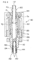
- FIG. 1 shows the entire construction of a motor-operated valve in accordance with the present invention.
- a motor-operated valve the whole of which is denoted by reference numeral 1 has a valve body 10, and a valve seat member 16 is inserted in the valve body 10.
- the valve body 10 is connected with pipes 20 and 22.
- a stator unit 40 of a stepping motor which is used as one example of drive motor, is mounted.
- a rotor unit 60 is rotatably disposed.
- the rotor unit 60 includes a rotor 62 consisting of a plastic magnet formed by mixing a magnetic material in a resin, and a screw feed member 70 connected to the rotor 62 via a ring member 64.
- the screw feed member 70 has a first screw portion S 1 and a second screw portion S 2 , which are formed in the same turning direction, and the pitch of the first screw portion S 1 is set so as to be larger than the pitch of the second screw portion S 2 .
- a stem member 110 fixed to the valve body 10 has an external thread portion engaging threadedly with the first screw portion S 1 .
- a rotation stopper member 80 is fixed on the outside of the screw feed member 70.
- the protruding portion of the rotation stopper member 80 abuts on the protruding portion of a stopper member 112 on the fixed side, by which the lower end position of the rotor unit 60 is regulated.
- a valve stem 120 is slidably inserted.
- a valve element 130 is installed, and a pressure is given to the valve element 130 by a coil spring 150.
- the valve element 130 controls the flow path opening area with respect to the valve seat member 16.
- An external thread member 160 attached to the upper part of the valve stem 120 has an external thread portion engaging threadedly with the second screw portion S 2 of the screw feed member 70. Above the external thread member 160, an urging spring 170 is installed to remove backlash of screw portion.
- the rotor unit 60 When the rotor unit 60 is rotated by receiving a pulse signal from the stator unit 40, the rotor unit 60 moves up and down corresponding to the screw pitch of the first screw portion S 1 engaging threadedly with the stem member 110.
- the feed amount (pitch) of the valve stem 120 is an amount obtained by subtracting the pitch of the second screw portion S 2 from the pitch of the first screw portion S 1 . That is to say, the first screw portion S 1 and the second screw portion S 2 constitute what is called a differential screw mechanism.
- the motor-operated valve in accordance with the present invention can increase the resolution of valve opening while the resolution of stepping motor is kept the same.
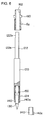
- FIG. 2 is an explanatory view showing a configuration of the motor-operated valve in a state in which the stator unit 40, the can 30, the pipes 20 and 22, and the like are removed.
- the rotor 62 constituting the rotor unit 60 is fixed to the screw feed member 70 via the ring member 64.
- Staking means K 1 is used as a fixing means
- the upper end portion of the valve stem 120 has a small-diameter portion 122
- the small-diameter portion 122 has a flat face in cross section, namely, is fabricated into a D cut face.
- the external thread member 160 is fitted on the valve stem 120 by utilizing the D cut face, and is fixed by staking means K 2 . By this configuration, the external thread member 160 is fixed to the valve stem 120 so as to provide a locking function to prevent the rotation of the valve stem.
- the screw feed member 70 and the external thread member 160 are engaged threadedly with each other via the second screw portion S 2 . When the screw feed member 70 is rotated together with the rotor 62, the valve stem 120 is moved up and down by the operation of the second screw portion S 2 .
- the screw feed member 70 has an internal thread portion, and is engaged threadedly with the external thread portion of the stem member 110 by the first screw portion S 1 .
- first screw portion S 1 and the second screw portion S 2 screw portions having the same direction are fabricated.
- first screw portion S 1 is fabricated into a screw having a nominal diameter of 6 mm and a pitch of 0.6 mm.
- the second screw portion S 2 is fabricated into a screw having a nominal diameter of 3.5 mm and a pitch of 0.5 mm.
- a motor-operated valve having only the first screw portion S 1 has a feed amount of 0.6 mm per one turn of rotor as a feed screw portion, so that the motor-operated valve can provide six times of control accuracy (resolution).
- this motor-operated valve requires a mechanism for sliding the valve stem 120 in the axial direction without rotating the valve stem 120 around the axis line.
- a locking member 140 is pressed into the tip end portion of the valve stem 120 under pressure, and is caused to abut on a guide member 144 pressed into the valve body 10 under pressure, by which a mechanism that stops the rotation and slides the valve stem 120 in the axial direction is formed.
- FIG. 3 shows principal elements before being assembled to the valve body 10.
- This figure shows a state in which the protruding portion in the lower end portion of the rotation stopper member 80 abuts on a protruding portion 112a of the stopper member 112 fixed to the stem member 110, by which the lower end position of the rotor unit is regulated.
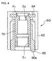
- FIG. 4 shows a general configuration of the rotor unit 60. This figure shows the internal thread portion of the first screw portion S 1 , the internal thread portion of the second screw portion S 2 , and a protrusion 80a formed in the lower end portion of the rotation stopper member 80.
- FIG. 5 shows a general configuration of a valve stem unit 100.
- the valve stem 120 is inserted slidably in the stem member 110, and the locking member 140 is pressed into the valve stem 120 under pressure.
- the locking member 140 has a flat face or a groove portion provided partially in a large-diameter portion 140a.
- the stopper member 144 fixed to the valve body 10 has a protruding portion 144a projecting to the inside, and the protruding portion 144a abuts on the flat face or the groove portion of the locking member 140, by which the turning of the valve stem 120 is restrained.
- FIG. 6 shows the assembly of valve stem and the details of the external thread member 160 attached to the small-diameter portion 122.
- the upper end portion of the small-diameter portion 122 of the valve stem 120 has a flat face 122b fabricated in a cylindrical face 122a.
- the external thread member 160 is fitted on the small-diameter portion of the valve stem 120, and staking is performed (K 2 portion shown in FIGS. 2 and 3), by which the external thread member 160 is fixed to the valve stem 120.
- the inside of the staking portion is pressed on the flat face 122b, which also restrains the turning of the valve stem 120.
- FIG. 7 shows a general configuration of the stem member.
- An inside-diameter portion 110a of the stem member 110 slidably receives the valve stem 120.
- the stopper member 112 is fixed.
- the stopper member 112 has the protruding portion 112a for stopper.
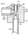
- FIG. 8 shows another example of the motor-operated valve in accordance with the present invention.
- the configuration in which the locking member 140 is inserted in a tip end portion 124 of the valve stem is the same as that of the above-described example.
- an orifice 200 is fixed to the valve body 10.
- the orifice 200 has a function of inhibiting air bubbles in the passing refrigerant from passing therethrough, and also the tip end portion thereof abuts on the locking member 140 so that the orifice 200 functions as a member for restraining the turning of the valve stem.
Applications Claiming Priority (1)
| Application Number | Priority Date | Filing Date | Title |
|---|---|---|---|
| JP2005146188A JP4781010B2 (ja) | 2005-05-19 | 2005-05-19 | 電動弁 |
Publications (2)
| Publication Number | Publication Date |
|---|---|
| EP1724460A1 true EP1724460A1 (fr) | 2006-11-22 |
| EP1724460B1 EP1724460B1 (fr) | 2008-09-17 |
Family
ID=36841018
Family Applications (1)
| Application Number | Title | Priority Date | Filing Date |
|---|---|---|---|
| EP06405212A Expired - Fee Related EP1724460B1 (fr) | 2005-05-19 | 2006-05-16 | Vanne actionnée par moteur |
Country Status (6)
| Country | Link |
|---|---|
| US (1) | US7494108B2 (fr) |
| EP (1) | EP1724460B1 (fr) |
| JP (1) | JP4781010B2 (fr) |
| KR (1) | KR101234937B1 (fr) |
| CN (1) | CN1865740B (fr) |
| DE (1) | DE602006002773D1 (fr) |
Cited By (7)
| Publication number | Priority date | Publication date | Assignee | Title |
|---|---|---|---|---|
| EP2284461A1 (fr) * | 2009-07-28 | 2011-02-16 | Hamilton Sundstrand Corporation | Vanne d'expansion pour système réfrigérant |
| EP2287548A3 (fr) * | 2009-07-17 | 2011-05-11 | Zhejiang Sanhua Co. Ltd. | Vanne d'expansion électronique |
| CN102252121A (zh) * | 2010-05-21 | 2011-11-23 | 浙江三花股份有限公司 | 一种电子膨胀阀 |
| KR200476020Y1 (ko) | 2013-01-03 | 2015-01-20 | 종산 강리 리프리저레이션 피팅스 컴퍼니 리미티드 | 전자 팽창 밸브 |
| EP3418613A4 (fr) * | 2016-02-18 | 2019-10-02 | Saginomiya Seisakusho, Inc. | Électrovanne |
| EP3696953A1 (fr) * | 2019-02-14 | 2020-08-19 | TGK CO., Ltd. | Vanne motorisée |
| WO2022143734A1 (fr) * | 2020-12-30 | 2022-07-07 | 浙江三花制冷集团有限公司 | Électrovanne |
Families Citing this family (27)
| Publication number | Priority date | Publication date | Assignee | Title |
|---|---|---|---|---|
| JP5249634B2 (ja) * | 2008-05-29 | 2013-07-31 | 株式会社不二工機 | 流量制御弁 |
| EP3062004B1 (fr) * | 2009-01-22 | 2017-08-16 | Fujikoki Corporation | Vanne motorisée |
| DE102009041964A1 (de) * | 2009-09-17 | 2011-06-09 | Mahle International Gmbh | Stellvorrichtung |
| US8960637B2 (en) * | 2009-11-18 | 2015-02-24 | Parker Hannifin Corporation | Electric expansion valve |
| JP5756606B2 (ja) * | 2010-06-25 | 2015-07-29 | 株式会社不二工機 | 雌ねじ部材、それを用いた電動弁及び電動弁用雌ねじ部材の製造方法 |
| JP5681396B2 (ja) * | 2010-06-29 | 2015-03-04 | 株式会社不二工機 | 電動弁 |
| JP5480753B2 (ja) * | 2010-08-25 | 2014-04-23 | 株式会社鷺宮製作所 | 電動弁 |
| US8690121B2 (en) * | 2011-03-30 | 2014-04-08 | Vetco Gray Inc. | Differential screw assembly for varying torque for valve |
| JP5400122B2 (ja) * | 2011-10-27 | 2014-01-29 | 株式会社鷺宮製作所 | 電動弁 |
| CN102927349A (zh) * | 2012-11-07 | 2013-02-13 | 陈国永 | 数字比例控制阀 |
| US9657656B2 (en) * | 2014-08-27 | 2017-05-23 | Continental Automotive Systems, Inc. | Idle air control valve for use in a small engine and having a protective shroud with valve seat |
| JP6604278B2 (ja) * | 2015-08-27 | 2019-11-13 | 株式会社Soken | 電動式流量制御弁 |
| DE102016203265A1 (de) * | 2016-02-29 | 2017-08-31 | Stabilus Gmbh | Stellanordnung und Klappensteuervorrichtung mit einer Stellanordnung |
| JP6721237B2 (ja) * | 2016-06-29 | 2020-07-08 | 株式会社不二工機 | 電動弁 |
| JP6476158B2 (ja) * | 2016-10-28 | 2019-02-27 | 株式会社不二工機 | 電動弁の組立方法 |
| JP6726124B2 (ja) * | 2017-03-23 | 2020-07-22 | 株式会社鷺宮製作所 | 電動弁およびそれを用いた冷凍サイクルシステム |
| CN107061807B (zh) * | 2017-03-29 | 2023-05-12 | 中船重工中南装备有限责任公司 | 全密封启闭充气阀 |
| JP6518713B2 (ja) * | 2017-04-12 | 2019-05-22 | 株式会社不二工機 | 電動弁 |
| JP6621793B2 (ja) * | 2017-11-20 | 2019-12-18 | 株式会社不二工機 | 電動弁 |
| WO2019105454A1 (fr) * | 2017-12-01 | 2019-06-06 | 浙江三花智能控制股份有限公司 | Vanne de détente électronique et système de refroidissement doté de celle-ci |
| CN109869488B (zh) | 2017-12-01 | 2021-10-01 | 浙江三花智能控制股份有限公司 | 电子膨胀阀及具有其的制冷系统 |
| IT201800007698A1 (it) * | 2018-07-31 | 2020-01-31 | Cmatic Spa | Raccordo a funzione |
| CN111059296B (zh) * | 2018-10-17 | 2022-02-08 | 浙江盾安禾田金属有限公司 | 电子膨胀阀 |
| CN111365515B (zh) * | 2018-12-25 | 2022-09-06 | 浙江盾安禾田金属有限公司 | 电子膨胀阀及使用该电子膨胀阀的空调系统 |
| CN210372066U (zh) * | 2019-06-14 | 2020-04-21 | 浙江盾安禾田金属有限公司 | 电子膨胀阀 |
| JP7176752B2 (ja) * | 2019-10-29 | 2022-11-22 | 株式会社不二工機 | 電動弁 |
| DE102020124870A1 (de) * | 2019-12-04 | 2021-06-10 | ECO Holding 1 GmbH | Expansionsventil |
Citations (5)
| Publication number | Priority date | Publication date | Assignee | Title |
|---|---|---|---|---|
| EP0361539A2 (fr) * | 1986-01-22 | 1990-04-04 | Otto Egelhof GmbH & Co. | Soupape d'expansion pour la régulation d'écoulement de réfrigérant vers un évaporateur d'installations frigorifiques ou de pompes à chaleur |
| EP0645569A2 (fr) * | 1993-09-24 | 1995-03-29 | Marotta Scientific Controls, Inc. | Soupape actionnée par moteur |
| US5851003A (en) * | 1996-05-31 | 1998-12-22 | Fujikoki Corporation | Motor operated valve |
| EP1087158A1 (fr) * | 1999-03-26 | 2001-03-28 | Kabushiki Kaisha Saginomiya Seisakusho | Soupape a commande electrique |
| WO2002023032A1 (fr) * | 2000-09-12 | 2002-03-21 | Berger Lahr Gmbh & Co. Kg | Verin de commande electromoteur a deux etapes, destine a une soupape |
Family Cites Families (11)
| Publication number | Priority date | Publication date | Assignee | Title |
|---|---|---|---|---|
| US2388989A (en) * | 1944-04-08 | 1945-11-13 | Shriver & Company Inc T | Diaphragm valve |
| US3409271A (en) * | 1966-05-04 | 1968-11-05 | Ideal Aerosmith Inc | Fluid flow control valve |
| JPS6187273U (fr) * | 1984-11-14 | 1986-06-07 | ||
| US5419530A (en) * | 1994-02-16 | 1995-05-30 | Teknocraft, Inc. | Micrometer-controlled linear flow rate fluid flow valve assembly |
| JP4224187B2 (ja) | 1999-06-02 | 2009-02-12 | 株式会社不二工機 | 電動弁 |
| JP4319322B2 (ja) * | 2000-03-22 | 2009-08-26 | シーケーディ株式会社 | 流量調整弁の組立方法と、その組立方法により組み立てられた流量調整弁 |
| JP2001280535A (ja) * | 2000-03-31 | 2001-10-10 | Saginomiya Seisakusho Inc | 電動式コントロールバルブ |
| JP2003097755A (ja) * | 2001-09-27 | 2003-04-03 | Saginomiya Seisakusho Inc | 電動弁とその組立方法 |
| CN2564804Y (zh) * | 2002-08-08 | 2003-08-06 | 怀琳 | 变频空调电子膨胀阀 |
| JP3723796B2 (ja) * | 2002-10-11 | 2005-12-07 | 三菱電機株式会社 | 自動変速装置の変速制御弁操作用アクチュエータ |
| JP4550528B2 (ja) * | 2004-09-01 | 2010-09-22 | 株式会社不二工機 | 電動弁 |
-
2005
- 2005-05-19 JP JP2005146188A patent/JP4781010B2/ja not_active Expired - Fee Related
-
2006
- 2006-05-01 US US11/414,930 patent/US7494108B2/en not_active Expired - Fee Related
- 2006-05-11 KR KR1020060042293A patent/KR101234937B1/ko active IP Right Grant
- 2006-05-16 DE DE602006002773T patent/DE602006002773D1/de active Active
- 2006-05-16 EP EP06405212A patent/EP1724460B1/fr not_active Expired - Fee Related
- 2006-05-17 CN CN2006100847066A patent/CN1865740B/zh not_active Expired - Fee Related
Patent Citations (5)
| Publication number | Priority date | Publication date | Assignee | Title |
|---|---|---|---|---|
| EP0361539A2 (fr) * | 1986-01-22 | 1990-04-04 | Otto Egelhof GmbH & Co. | Soupape d'expansion pour la régulation d'écoulement de réfrigérant vers un évaporateur d'installations frigorifiques ou de pompes à chaleur |
| EP0645569A2 (fr) * | 1993-09-24 | 1995-03-29 | Marotta Scientific Controls, Inc. | Soupape actionnée par moteur |
| US5851003A (en) * | 1996-05-31 | 1998-12-22 | Fujikoki Corporation | Motor operated valve |
| EP1087158A1 (fr) * | 1999-03-26 | 2001-03-28 | Kabushiki Kaisha Saginomiya Seisakusho | Soupape a commande electrique |
| WO2002023032A1 (fr) * | 2000-09-12 | 2002-03-21 | Berger Lahr Gmbh & Co. Kg | Verin de commande electromoteur a deux etapes, destine a une soupape |
Cited By (9)
| Publication number | Priority date | Publication date | Assignee | Title |
|---|---|---|---|---|
| EP2287548A3 (fr) * | 2009-07-17 | 2011-05-11 | Zhejiang Sanhua Co. Ltd. | Vanne d'expansion électronique |
| CN101956830B (zh) * | 2009-07-17 | 2013-06-12 | 浙江三花股份有限公司 | 电子膨胀阀 |
| US8556229B2 (en) | 2009-07-17 | 2013-10-15 | Zhejiang Sanhua Co., Ltd. | Electronic expansion valve |
| EP2284461A1 (fr) * | 2009-07-28 | 2011-02-16 | Hamilton Sundstrand Corporation | Vanne d'expansion pour système réfrigérant |
| CN102252121A (zh) * | 2010-05-21 | 2011-11-23 | 浙江三花股份有限公司 | 一种电子膨胀阀 |
| KR200476020Y1 (ko) | 2013-01-03 | 2015-01-20 | 종산 강리 리프리저레이션 피팅스 컴퍼니 리미티드 | 전자 팽창 밸브 |
| EP3418613A4 (fr) * | 2016-02-18 | 2019-10-02 | Saginomiya Seisakusho, Inc. | Électrovanne |
| EP3696953A1 (fr) * | 2019-02-14 | 2020-08-19 | TGK CO., Ltd. | Vanne motorisée |
| WO2022143734A1 (fr) * | 2020-12-30 | 2022-07-07 | 浙江三花制冷集团有限公司 | Électrovanne |
Also Published As
| Publication number | Publication date |
|---|---|
| CN1865740A (zh) | 2006-11-22 |
| EP1724460B1 (fr) | 2008-09-17 |
| CN1865740B (zh) | 2010-12-01 |
| DE602006002773D1 (de) | 2008-10-30 |
| JP2006322535A (ja) | 2006-11-30 |
| US7494108B2 (en) | 2009-02-24 |
| JP4781010B2 (ja) | 2011-09-28 |
| KR101234937B1 (ko) | 2013-02-19 |
| US20060261302A1 (en) | 2006-11-23 |
| KR20060120417A (ko) | 2006-11-27 |
Similar Documents
| Publication | Publication Date | Title |
|---|---|---|
| US7494108B2 (en) | Motor-operated valve | |
| JP4812601B2 (ja) | 電動弁 | |
| EP1632703B1 (fr) | Vanne actionnée par moteur | |
| EP1816380B1 (fr) | Vanne de débit | |
| CN111396618B (zh) | 电动阀 | |
| JP6845817B2 (ja) | 電動弁及び冷凍サイクルシステム | |
| US10795381B2 (en) | Flow-rate adjustable valve | |
| JP2018003899A (ja) | 電動弁 | |
| US20170321809A1 (en) | Flow-rate adjustable valve and method of manufacturing the same | |
| JP2010025184A (ja) | 電動弁 | |
| EP2868970B1 (fr) | Dispositif de régulation | |
| EP0494511A2 (fr) | Régulateur du débit | |
| JP3972340B2 (ja) | 流量制御装置 | |
| JP2000179731A (ja) | 電動弁 | |
| JP4738065B2 (ja) | 1回転電動弁 | |
| CN110345292B (zh) | 电动阀 | |
| JP5830567B2 (ja) | 電動弁 | |
| JP2009036346A (ja) | 流量調節バルブ | |
| JP2007032675A (ja) | 電動弁 | |
| JP2023165418A (ja) | 電動弁 | |
| JP2007010014A (ja) | 電動流量制御弁 |
Legal Events
| Date | Code | Title | Description |
|---|---|---|---|
| PUAI | Public reference made under article 153(3) epc to a published international application that has entered the european phase |
Free format text: ORIGINAL CODE: 0009012 |
|
| AK | Designated contracting states |
Kind code of ref document: A1 Designated state(s): AT BE BG CH CY CZ DE DK EE ES FI FR GB GR HU IE IS IT LI LT LU LV MC NL PL PT RO SE SI SK TR |
|
| AX | Request for extension of the european patent |
Extension state: AL BA HR MK YU |
|
| 17P | Request for examination filed |
Effective date: 20070518 |
|
| AKX | Designation fees paid |
Designated state(s): DE FR GB IT |
|
| GRAP | Despatch of communication of intention to grant a patent |
Free format text: ORIGINAL CODE: EPIDOSNIGR1 |
|
| RIN1 | Information on inventor provided before grant (corrected) |
Inventor name: HIGUCHI, KOUJI C/O FUJIKOKI CORPORATION Inventor name: INOUE, YASUSHI C/O FUJIKOKI CORPORATION Inventor name: UMEZAWA, HITOSHI C/O FUJIKOKI CORPORATION |
|
| GRAS | Grant fee paid |
Free format text: ORIGINAL CODE: EPIDOSNIGR3 |
|
| GRAA | (expected) grant |
Free format text: ORIGINAL CODE: 0009210 |
|
| AK | Designated contracting states |
Kind code of ref document: B1 Designated state(s): DE FR GB IT |
|
| REG | Reference to a national code |
Ref country code: GB Ref legal event code: FG4D |
|
| REF | Corresponds to: |
Ref document number: 602006002773 Country of ref document: DE Date of ref document: 20081030 Kind code of ref document: P |
|
| PLBE | No opposition filed within time limit |
Free format text: ORIGINAL CODE: 0009261 |
|
| STAA | Information on the status of an ep patent application or granted ep patent |
Free format text: STATUS: NO OPPOSITION FILED WITHIN TIME LIMIT |
|
| 26N | No opposition filed |
Effective date: 20090618 |
|
| REG | Reference to a national code |
Ref country code: DE Ref legal event code: R084 Ref document number: 602006002773 Country of ref document: DE |
|
| REG | Reference to a national code |
Ref country code: GB Ref legal event code: 746 Effective date: 20110513 |
|
| PGFP | Annual fee paid to national office [announced via postgrant information from national office to epo] |
Ref country code: GB Payment date: 20140514 Year of fee payment: 9 |
|
| PGFP | Annual fee paid to national office [announced via postgrant information from national office to epo] |
Ref country code: DE Payment date: 20140515 Year of fee payment: 9 Ref country code: FR Payment date: 20140509 Year of fee payment: 9 |
|
| PGFP | Annual fee paid to national office [announced via postgrant information from national office to epo] |
Ref country code: IT Payment date: 20140507 Year of fee payment: 9 |
|
| REG | Reference to a national code |
Ref country code: DE Ref legal event code: R119 Ref document number: 602006002773 Country of ref document: DE |
|
| GBPC | Gb: european patent ceased through non-payment of renewal fee |
Effective date: 20150516 |
|
| PG25 | Lapsed in a contracting state [announced via postgrant information from national office to epo] |
Ref country code: IT Free format text: LAPSE BECAUSE OF NON-PAYMENT OF DUE FEES Effective date: 20150516 |
|
| REG | Reference to a national code |
Ref country code: FR Ref legal event code: ST Effective date: 20160129 |
|
| PG25 | Lapsed in a contracting state [announced via postgrant information from national office to epo] |
Ref country code: DE Free format text: LAPSE BECAUSE OF NON-PAYMENT OF DUE FEES Effective date: 20151201 Ref country code: GB Free format text: LAPSE BECAUSE OF NON-PAYMENT OF DUE FEES Effective date: 20150516 |
|
| PG25 | Lapsed in a contracting state [announced via postgrant information from national office to epo] |
Ref country code: FR Free format text: LAPSE BECAUSE OF NON-PAYMENT OF DUE FEES Effective date: 20150601 |