EP1724071A1 - Master-slave manipulator system and its operation input device - Google Patents
Master-slave manipulator system and its operation input device Download PDFInfo
- Publication number
- EP1724071A1 EP1724071A1 EP06010411A EP06010411A EP1724071A1 EP 1724071 A1 EP1724071 A1 EP 1724071A1 EP 06010411 A EP06010411 A EP 06010411A EP 06010411 A EP06010411 A EP 06010411A EP 1724071 A1 EP1724071 A1 EP 1724071A1
- Authority
- EP
- European Patent Office
- Prior art keywords
- manipulator
- input device
- mode
- arm
- operation input
- Prior art date
- Legal status (The legal status is an assumption and is not a legal conclusion. Google has not performed a legal analysis and makes no representation as to the accuracy of the status listed.)
- Withdrawn
Links
Images


Classifications
-
- B—PERFORMING OPERATIONS; TRANSPORTING
- B25—HAND TOOLS; PORTABLE POWER-DRIVEN TOOLS; MANIPULATORS
- B25J—MANIPULATORS; CHAMBERS PROVIDED WITH MANIPULATION DEVICES
- B25J3/00—Manipulators of master-slave type, i.e. both controlling unit and controlled unit perform corresponding spatial movements
- B25J3/04—Manipulators of master-slave type, i.e. both controlling unit and controlled unit perform corresponding spatial movements involving servo mechanisms
-
- A—HUMAN NECESSITIES
- A61—MEDICAL OR VETERINARY SCIENCE; HYGIENE
- A61B—DIAGNOSIS; SURGERY; IDENTIFICATION
- A61B34/00—Computer-aided surgery; Manipulators or robots specially adapted for use in surgery
- A61B34/30—Surgical robots
- A61B34/37—Master-slave robots
-
- A—HUMAN NECESSITIES
- A61—MEDICAL OR VETERINARY SCIENCE; HYGIENE
- A61B—DIAGNOSIS; SURGERY; IDENTIFICATION
- A61B34/00—Computer-aided surgery; Manipulators or robots specially adapted for use in surgery
- A61B34/70—Manipulators specially adapted for use in surgery
-
- B—PERFORMING OPERATIONS; TRANSPORTING
- B25—HAND TOOLS; PORTABLE POWER-DRIVEN TOOLS; MANIPULATORS
- B25J—MANIPULATORS; CHAMBERS PROVIDED WITH MANIPULATION DEVICES
- B25J13/00—Controls for manipulators
- B25J13/02—Hand grip control means
-
- B—PERFORMING OPERATIONS; TRANSPORTING
- B25—HAND TOOLS; PORTABLE POWER-DRIVEN TOOLS; MANIPULATORS
- B25J—MANIPULATORS; CHAMBERS PROVIDED WITH MANIPULATION DEVICES
- B25J19/00—Accessories fitted to manipulators, e.g. for monitoring, for viewing; Safety devices combined with or specially adapted for use in connection with manipulators
- B25J19/0004—Braking devices
-
- B—PERFORMING OPERATIONS; TRANSPORTING
- B25—HAND TOOLS; PORTABLE POWER-DRIVEN TOOLS; MANIPULATORS
- B25J—MANIPULATORS; CHAMBERS PROVIDED WITH MANIPULATION DEVICES
- B25J9/00—Programme-controlled manipulators
- B25J9/16—Programme controls
- B25J9/1674—Programme controls characterised by safety, monitoring, diagnostic
- B25J9/1676—Avoiding collision or forbidden zones
-
- B—PERFORMING OPERATIONS; TRANSPORTING
- B25—HAND TOOLS; PORTABLE POWER-DRIVEN TOOLS; MANIPULATORS
- B25J—MANIPULATORS; CHAMBERS PROVIDED WITH MANIPULATION DEVICES
- B25J9/00—Programme-controlled manipulators
- B25J9/16—Programme controls
- B25J9/1679—Programme controls characterised by the tasks executed
- B25J9/1689—Teleoperation
-
- A—HUMAN NECESSITIES
- A61—MEDICAL OR VETERINARY SCIENCE; HYGIENE
- A61B—DIAGNOSIS; SURGERY; IDENTIFICATION
- A61B34/00—Computer-aided surgery; Manipulators or robots specially adapted for use in surgery
- A61B34/30—Surgical robots
-
- A—HUMAN NECESSITIES
- A61—MEDICAL OR VETERINARY SCIENCE; HYGIENE
- A61B—DIAGNOSIS; SURGERY; IDENTIFICATION
- A61B90/00—Instruments, implements or accessories specially adapted for surgery or diagnosis and not covered by any of the groups A61B1/00 - A61B50/00, e.g. for luxation treatment or for protecting wound edges
- A61B90/36—Image-producing devices or illumination devices not otherwise provided for
- A61B90/361—Image-producing devices, e.g. surgical cameras
-
- G—PHYSICS
- G05—CONTROLLING; REGULATING
- G05B—CONTROL OR REGULATING SYSTEMS IN GENERAL; FUNCTIONAL ELEMENTS OF SUCH SYSTEMS; MONITORING OR TESTING ARRANGEMENTS FOR SUCH SYSTEMS OR ELEMENTS
- G05B2219/00—Program-control systems
- G05B2219/30—Nc systems
- G05B2219/39—Robotics, robotics to robotics hand
- G05B2219/39088—Inhibit movement in one axis if collision danger
-
- G—PHYSICS
- G05—CONTROLLING; REGULATING
- G05B—CONTROL OR REGULATING SYSTEMS IN GENERAL; FUNCTIONAL ELEMENTS OF SUCH SYSTEMS; MONITORING OR TESTING ARRANGEMENTS FOR SUCH SYSTEMS OR ELEMENTS
- G05B2219/00—Program-control systems
- G05B2219/30—Nc systems
- G05B2219/39—Robotics, robotics to robotics hand
- G05B2219/39114—Hand eye cooperation, active camera on first arm follows movement of second arm
-
- G—PHYSICS
- G05—CONTROLLING; REGULATING
- G05B—CONTROL OR REGULATING SYSTEMS IN GENERAL; FUNCTIONAL ELEMENTS OF SUCH SYSTEMS; MONITORING OR TESTING ARRANGEMENTS FOR SUCH SYSTEMS OR ELEMENTS
- G05B2219/00—Program-control systems
- G05B2219/30—Nc systems
- G05B2219/40—Robotics, robotics mapping to robotics vision
- G05B2219/40161—Visual display of machining, operation, remote viewing
-
- G—PHYSICS
- G05—CONTROLLING; REGULATING
- G05B—CONTROL OR REGULATING SYSTEMS IN GENERAL; FUNCTIONAL ELEMENTS OF SUCH SYSTEMS; MONITORING OR TESTING ARRANGEMENTS FOR SUCH SYSTEMS OR ELEMENTS
- G05B2219/00—Program-control systems
- G05B2219/30—Nc systems
- G05B2219/40—Robotics, robotics mapping to robotics vision
- G05B2219/40181—Operator can fine position in small area, free, but if contact, force feedback
-
- G—PHYSICS
- G05—CONTROLLING; REGULATING
- G05B—CONTROL OR REGULATING SYSTEMS IN GENERAL; FUNCTIONAL ELEMENTS OF SUCH SYSTEMS; MONITORING OR TESTING ARRANGEMENTS FOR SUCH SYSTEMS OR ELEMENTS
- G05B2219/00—Program-control systems
- G05B2219/30—Nc systems
- G05B2219/40—Robotics, robotics mapping to robotics vision
- G05B2219/40212—Two-way clutch for joint, prevents movement in unallowable direction
-
- G—PHYSICS
- G05—CONTROLLING; REGULATING
- G05B—CONTROL OR REGULATING SYSTEMS IN GENERAL; FUNCTIONAL ELEMENTS OF SUCH SYSTEMS; MONITORING OR TESTING ARRANGEMENTS FOR SUCH SYSTEMS OR ELEMENTS
- G05B2219/00—Program-control systems
- G05B2219/30—Nc systems
- G05B2219/40—Robotics, robotics mapping to robotics vision
- G05B2219/40478—Graphic display of work area of robot, forbidden, permitted zone
-
- G—PHYSICS
- G05—CONTROLLING; REGULATING
- G05B—CONTROL OR REGULATING SYSTEMS IN GENERAL; FUNCTIONAL ELEMENTS OF SUCH SYSTEMS; MONITORING OR TESTING ARRANGEMENTS FOR SUCH SYSTEMS OR ELEMENTS
- G05B2219/00—Program-control systems
- G05B2219/30—Nc systems
- G05B2219/45—Nc applications
- G05B2219/45118—Endoscopic, laparoscopic manipulator
Definitions
- the present invention relates to a master-slave manipulator system and this operation input devices.
- JP-A-7-124876 discloses such a configuration that a position restricting member is arranged in an operation range of an operation input device, corresponding to a position of an obstacle against the manipulator arm, in order to prevent the operation input device from entering an area where the operation of the manipulator arm is inhibited.
- JP-A-2004-223128 discloses a configuration in which data of an operation range of a manipulator arm is previously acquired from a diagnostic tool, and an area where the manipulator arm can move for treatment is set according to the data, and when the operator comes near to move the manipulator arm out of the set area, a motor provided in an operation input device restricts the operation range of the operation input device so as to prevent the manipulator arm from moving out of the set area.
- JP-A-11-333764 when the arm makes contact with the object, a variable power transmission unit gives a force feedback to an operation input device, so as to make to feel a resistive force.
- an operation input device for preventing the operation input device from moving in an area where the operation of the manipulator arm is inhibited, an operation input device is provided with an actuator for feeding back a force to the operator, so as to restrict the operation of the operation input device.
- the actuator provided in the operation input device would cause an increase in the size of the operation input device, and additionally, a failure thereof or the like results in an excessive large force applied to the operator.
- the manipulator system causes problems of complicated control and vibrating behavior at an interface between a zone where a wall is sensed and a free operation zone.
- a usual motor could be hardly used as the actuator.
- a surgical support manipulator system utilizing an MRI unit as a diagnostic tool can hardly use an operation input device utilizing a motor which would cause noise interference with the MRI unit.
- the configuration disclosed in the patent document 2 discloses a method of setting a range where the manipulator arm can be operated, but, does not involve the use of any actuator other than the motor for restricting a possible operation range of the operation input device.
- the patent document 3 discloses the proposal of presenting a force feed-back in the operation input device when the slave arm makes contact with an object, but it is not adapted to be use for avoiding an obstacle or a hazard zone. Further, it also discloses the mechanism that when the manipulator arm does not make contact with the object the operation is not influenced by a motor with the use of the variable power transmission unit. But even if the manipulator arm makes contact with the object, a force feed-back is presented with the use of a power from the motor.
- An object of the present invention is to provide a master-slave manipulator system and an operation input device therefor, which are capable of presenting an obstacle or a limit to an operation range as a force feed-back with no use of a motor in the operation input device, and which have high reliability, a small-size and good operability.
- a master-slave manipulator system comprising a manipulator having an arm, an operation input device for moving the arm of the manipulator, and a controller for controlling the manipulator and the operation input device, and the operation input devise comprises on joints a mode change-over mechanism.
- the mode change-over mechanism has at least three modes: of which, in a first mode, power is not transmitted; in a second mode, power is transmitted in one direction and is not transmitted in a reverse direction thereof; and in a third mode, power is transmitted in the reverse direction and is not transmitted in the one direction, selects one of the above modes and changes over from one mode to the selected mode.
- the configurations (1) to (8) may be combined in different manners in dependence on the demands of the application.
- an operation input device for moving an arm of a manipulator in a master-slave manipulator system comprising on joints thereof, a mode change-over mechanism which has at least three modes: of which, in a first mode, power is not transmitted; in a second mode, power is transmitted in one direction and is not transmitted in a reverse direction thereof; and, in a third mode, power is transmitted in the reverse direction and is not transmitted in the one direction, selects one of the above modes and changes over from one mode to the selected mode.
- a master-slave manipulator system and an operation input device which are capable of presenting an obstacle and a limit to an operation range as a force feed-back with no use of a motor in the operation input device, and which have high reliability, a small-size and good operability.
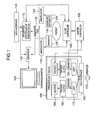
- Fig. 1 shows an overall configuration of a master-slave manipulator system according to an embodiment of the present invention, which is used as a surgical support system as an example.
- An operator 170 may manipulate an endoscopic instrument 135 which is located at the distal end of a second manipulator 130 with the use of an input interface 165 of an operation input device 190, while referring to the endoscopic instrument 135 an image of which is picked up by an endoscope 125 held by a first manipulator 110.
- An image displayed on a reference monitor 100 is picked up from an affected part of the patient 140 by the endoscope 125 held by the first manipulator 110, and accordingly, the endoscopic instrument 135 may also fall in the viewing field of the endoscope 125 together with the affected part of the patient 140.
- the first manipulator 110 may be also moved with the use of the operation input device 190, similar to the second manipulator 130.
- Data as to the affected part of the patient 140 is acquired by a diagnostic tool 120 before or during surgical operation, and is delivered to an integrated controller of position datum 115.
- a safety area where the manipulators 110, 130 may be operated, and a hazard area where the manipulators 110, 130 have to not move are inputted by the interface 116 or an interface 165 of the operation input device 106.
- the data as to the safety area (a possible operation area) or the hazard range may be displayed on the reference monitor 100 through the intermediary of a converter 105, being overlapped with the image of the endoscope 125.
- Data of the manipulators 110, 130 is delivered to a slave controller 145 while data as to positions and orientations of the manipulators 110, 130 is delivered to the integrated controller of position of datum 115.
- the integrated controller of position of datum 115 compares data as to the set safety area and the set hazard area with data as to the present positions of the manipulators 110, 130, and calculates a direction in which the manipulators 110, 130 should not be moved when the manipulators 110, 130 are to be out of the safety area or to enter the hazard area, and transmits the thus obtained data to the slave controller 140, which in turn transmits the data to a master controller 150.
- the master controller 150 energizes solenoids 185 in one or more joints 175 in the operation input device 190 corresponding to the direction in which the manipulators 110, 130 should not be moved, so as to connect power transmission of a two-way clutch 180 in order to restrain the input interface 165 of the operation input device 190 from moving in the direction in which the manipulators 110, 130 should not be moved.
- the two-way clutch 180 attached to each of the joints 175 is set in a disconnecting condition of power transmission by the solenoid 185, and accordingly, the operator 170 can optionally move the input interface 165.
- Each joint 175 is provided thereto with sensors 155 which include an encoder and a potentiometer and from which acquired data of displacement of the joint is delivered to the master controller 150.
- the master controller 150 calculates a direction in which the operator desires to move the manipulators 110, 130 and orientations thereof from the data of displacement of the joint, and transmits the thus calculated data to the slave controller 145.
- the slave controller 145 therefore calculates inverse kinematics of the manipulators 110, 130 so as to drive the joints of the manipulators 110, 130 in order to cause the manipulators 110, 130 to carry out a motion intended by the operator 170.
- the endoscope 125 and the endoscopic instrument are operated as the operator intends.
- the diagnostic tool 120 may be any one of an MRI unit, a CT unit, an ultrasonic probe, a laser range finder or an endoscope, which can display data of and around an affected part by images, CG or the like.
- the input interface 116 is a position/orientation input device composed of a mouse, a joystick, a keyboard and the like.
- the diagnostic image coordination system of the diagnostic tool 120 and the coordination system of the manipulators 110, 130 can be synthesized by physically constraining the bases of the diagnostic tool 120 and the manipulators 110, 130, or by synthesizing transformation matrix obtained by measuring the diagnostic tool 120 and the manipulators 110, 130 with the use of a three-dimensional position measuring unit which is not shown.
- Fig. 2 shows such a condition that the operator 170 carries out the handling of the manipulators 110, 130 by means of the operation input device 190.
- the operator 170 sits on a chair 230, sets his elbows or forearms on the armrest 235 thereof, grips gripping portions 200 serving as the input interface 165 so as to manipulate the gripping portions 200 while he observes the reference monitor 100 in order to move the manipulators displayed on the reference monitor 100 or the viewing field of the endoscope 125 for transmitting an image to the display monitor 100.
- the gripping portions 200 are linked to a console 240 through the intermediary of a plurality of links 205, 210, 225, 220, 215 and the like. These links are associated with one another serving as rotating joints and translation joints. By applying the configuration in this embodiment to each joint, as will be explained later, the gripping portions 200 can be optionally moved or can be restrained from moving in a certain direction.
- the joint mechanism will be detailed later with reference to Fig. 5.
- Fig. 2 although the gripping portion 200 is shown only for the right hand of the operator 170, there may be provided another gripping portion 200 serving as a similar interface 165 for the left hand.
- the arm rest 235 is arranged on members extended from a center pole of the console 240, at a position where it does not physically interfere with the operation range of the operation input devise 190.
- the member linking the center pole of the console 240 and the armrest 235 is mounted thereon with command input switches for the operation input device 190 and data information presenting lamps which are not shown.
- Fig. 3 shows a condition of disconnection and connection of power transmission with the use of the two-way clutch 180 provided in each of the translation joints 175 of the operation input device 190 shown in Fig. 1.
- a condition in which the power transmission of the two-way clutch 180 is disconnected is indicated by the solid line
- a condition in which the power transmission of the two-way clutch 180 is connected in either one of directions thereof but the power transmission is disconnected in the other direction so that the joint may be freely rotated is indicated by the chain line.
- the components indicated by the solid line are denoted by reference numerals with a suffix a
- the components indicated by the chain line are denoted by reference numerals with a suffix b or c.
- the suffixes a to c will be omitted in the explanation.
- the two-way clutch 180 is provided with a lever 215, a housing 320 and a bearing 325.
- a shaft 330 arranged on the inner diameter side of the bearing 325 can be freely rotated.
- the lever 315 is turned to the right side in the figure so that the lever 315 is set on the right side with respect to the housing 320 as indicated by the chain line 315b, the shaft 330 arranged on the inner diameter side of the bearing 325 can not be rotated in the direction of the arrow 345 but may be freely rotated in the direction of the arrow 350.
- the shaft 330 arranged on the inner diameter side of the bearing 325 can not be rotated in the direction of the arrow 350 but may be freely rotated in the direction of the arrow 345.
- the link 305 integrally incorporated with the rod 300 has an elongated hole 306, and is connected to the lever 315 through the intermediary of the shaft 310, which is integrally incorporated with the lever 315.
- the shaft 330 arranged on the inner diameter side of the bearing 325 can be freely rotated.
- the shaft 330 is operated in synchronization with a pinion gear 335 coaxial therewith. Further, the pinion gear 335 is meshed with a rack 340, which is stationary.
- the housing 320 may be freely moved in a direction 355 or 360 when a force is exerted to the housing 320 in the direction 355 or 360 if the lever 315 is set in the condition of the lever 315a indicated by the solid line.
- the shaft 330 and the pinion gear 335 moved integrally therewith can not be rotated in the direction of the arrow 345 but may be moved only in the direction of the arrow 350.
- the housing 320 can not be moved in the direction of the arrow 360. Meanwhile, it may be freely moved in the direction of the arrow 355.
- the link 305 integrally incorporated with the rod 300c is turned into a condition of the link 305c indicated by the chain line.
- the shaft 310 is moved through the elongated hole 306 in the link 305 and is turned into a condition of the shaft 310c indicated by the chain line, and the lever 315 integrally incorporated with the shaft 310 is turned into a condition of the lever 315c indicated by the chin line.
- the shaft 330 and the pinion gear 335 moved integrally therewith can not be rotated in the direction of the arrow 350, but may be rotated only in the direction of the arrow 345.
- the housing 320 can not be moved in the direction of the arrow 355 even though a force is exerted to the housing 320 in the direction of the arrow 355. Meanwhile, it may be freely moved in the direction of the arrow 360.
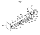
- Fig. 4 is a perspective view illustrating the translation joint mechanism for one axial part using the two-way clutch 180 shown in Fig. 3.
- the translation join mechanism moves a rod 410 in the direction of the arrow 406 or the direction of the arrow 407 with respect to a base 420, and some similar joint mechanisms are connected subsequent to the base 415 of the next joint, and are finally linked to the gripping portions 200 (refer to Fig. 2).
- the base 420 is fixed thereto with a linear guide rail 425 and a rack 340, and a guide base 440 is attached to a guide 430 moved on the linear guide rail 425.
- a rod 410 is secured by means of a rod fixture 435
- the housing 320 is secured by a clutch fixture 405.
- a 3 position solenoid 400 (corresponding to the solenoid 185 shown in Fig. 1) for moving a lever of the two-way clutch.
- the 3 position solenoid 400 may move and hold the rod 300 in three conditions (rod 300a, 300b and 300c) as explained with reference to Fig. 3.
- the master controller 150 calculates such a condition that if the operation input device 190 is moved in the direction of the arrow 406, there is presented a hazard area in the moving direction of the manipulator 110 or 130 which is moved in association with the operation input device 190, and thus, the manipulator 110 or 130 should not be moved in the direction.
- the master controller 150 issues a signal for energizing the 3 position solenoid 400 so as to move the lever 315 and to connect the power transmission function of the two-way clutch, resulting in such a condition that the pinion gear 335 can not be rotated in the direction of the arrow 345 but may be rotated in the direction of the arrow 350.
- the guide 430 may move in the direction of the arrow 407 but can not move in the direction of the arrow 406 according to the meshing between the pinion gear 335 and the rack 340.
- the operator 170 may input his manipulation in the direction of the arrow 407 on the safety side but can not input his manipulation in the direction of the arrow 406 toward the hazard area, thereby it is possible to solve such a problem that the manipulator 110 or 130 is moved into the hazard range.
- the master controller 150 calculates such a condition that at the time if the operation input device 190 is to be moved in the direction of the arrow 407, there is presented a hazard area in the moving direction of the manipulator 110 or 130 which is moved in association with the operation input device 190, and accordingly, the manipulator should not be moved in this direction.
- the master controller 150 issues a signal for energizing the 3 position solenoid 400 so as to move the lever 315 and to connect the power transmission connection of the two-way clutch, resulting in such a condition that the pinion gear 335 can not be rotated in the direction of the arrow 350 but may be rotated in the direction of the arrow 345.
- the guide 430 may move in the direction of the arrow 406 but can not move in the direction of the arrow 407 according to the meshing between the pinion gear 335 and the rack 340.
- the displacement amount of the joint is measured by a linear encoder which is although not shown, and accordingly, a manipulation input amount may be acquired by the master controller 150.
- Fig. 5 shows an entire configuration of the operation input device 190 in this embodiment from which the console 240 is eliminated.
- a base 585 is attached to the rear surface of the console 240 shown in Fig. 2.
- a base 575 and a linear guide rail 580 fixed to the rear surface of the base 585 are linked to each other through the intermediary of translation joints so that the base 575 is moved on the linear guide rail 580 in the direction of the arrow 578, that is, in the left and right directions.
- a mode change-over mechanism which according to the present invention is also attached to this translation joints which are moved in the direction of the arrow 578 although it is hidden behind the base 585 so that it is invisible.
- a rod 560 is translated in the direction of the arrow 563 which is a vertical direction with respect to the base 575 through the intermediary of a mode change-over mechanism 565 meshed with a rack 570 attached to the base 575.
- a rod 535 is translated with respect to a base 550 in the direction of the arrow 537 which is a longitudinal direction through the intermediary of a mode change-over mechanism 540 meshed with a rack 545 fixed to the base 550.
- a fixture 530 mounted to the rod 535 is connected to a link 520 through the intermediary of a shaft 525, and the link 520 serves as a rotating joint by means of the shaft 525.
- the link 520 is connected a link 510, using the shaft 515 as a rotary shaft, and the link 510 is connected to the gripping portions 200 through the intermediary of the shaft 505.
- the operation input device 190 shown in Fig. 5 is composed of three translation joints and three rotating joints, and accordingly, the operator may input positions and orientations in six degrees of freedom. It is noted that the gripping portions 200 are provided with opening and closing joints for the endoscopic equipment.
- the translation joints corresponding to the arrows 563, 537 are provided with constant force springs which are not shown, in order to compensate the dead weight of the operation input device.
- the operator 170 may freely manipulate the operation input device 190 with no feel of the dead weight thereof when the manipulation is made by holding the gripping portions 200.
- the mode change-over mechanism may be materialized in such a way that the shaft 330 shown in Fig. 3 is used as a joint shaft while the housing 220 is fixed to a link of the base, and a link of the next joint is secured to the shaft 330, instead of the pinion gear 350.
- the input of an orientation is optional, and accordingly, only the input of a position may be limited.
- the position and orientation in six degrees of freedom may be limited.
- Figs. 6 and 7 are plan views illustrating the gripping portion 200 in this embodiment in different conditions.
- Movable components in the gripping portion 200 are denoted by reference numerals with a suffix a in the condition shown in Fig. 6, and with a suffix b in the condition shown in Fig. 7.
- the components will be explained being generally denoted by reference numerals with no suffixes a to b.
- the forefinger and the thumb touch blades 625, 640 so as to input an opening and closing manipulation to the endoscopic instrument 165.
- the blade 625 may be also symmetrically moved, and on the contrary, only by moving the blade 625, the blade 640 may be also similarly moved.
- the opening and closing manipulation it is possible to accept three cases, that is, a person desires to use only his thumb, or a person desires only his forefinger, and a person desires to use both thumb and forefinger.
- a cam retainer 605 integrally incorporated with the base 630 is formed therein with a hole 606 through which a cam plate 610 may be translated.
- a shaft 615 is serving as a rotating center shaft of the blades 625, 640, and pierces through the base 630 so as to serve as a mode change-over mechanism 645. Since the shaft 615 is rotated integrally with the blade 625, the opening angle of the blades may be limited by the mode change-over mechanism 645.
- the mode change-over mechanism 645 includes a 3 position solenoid 600. Further, the opening angle of the blades may be acquired by an encoder which is not shown.
- the shaft 615 pierces through a cam hole 651 in the cam plate 610, and a shaft 650 integrally incorporated with the blade 640 and a shaft 620 integrally incorporated with the blade 625 pierce through the cam hole 651 in the cam plate 610.
- the opening degree of the gripping portion may be limited or the gripping portion may be held in a closed condition.
- the operator 170 may eliminate the necessity of gripping with a strong force while he grips an object such as a needle, thereby it is possible to alleviate fatigue or the like.
- the blades 640, 625 are normally opened by springs which are not shown, as shown in Fig. 6.
- An opening and closing base 630 is provided thereto with a micro-switch 635 which responds when it is firmly pressed after the blade 640a is turned into the blade 640b.
- the mode change-over mechanism 645 is operated so that the blades 640, 625 are held in the closed condition.
- another button which is not shown is depressed by a finger, and accordingly, the blades 640, 625 may be released from the closed condition.
- the mode change-over mechanism 645 is used.
- the directions of connection of the power transmission and the disconnection thereof are controlled by the master controller 150, and accordingly, softness and hardness upon contact of the manipulator arm with an object may be exhibited as a force feed-back in addition to the exhibition of an obstacle or a wall of a hazard area. That is, the controller 150 selects the mode of the mode change-over mechanism multiple times and in a variable manner of the duty ratio so as to finely change over the connection, and accordingly, a force feed-back is exhibited when the arm of the manipulator 110 or 130 touches the object.
- the operation input device 190 when no presentation of a safety area or a hazard area is required, the operation input device 190 may be optionally moved, but when the presentation of the safety area or the hazard area is required, the motion toward the hazard area can be limited with no use of a motor while the motion toward the safety area may be optionally made. Further, an operating range limited by the operator and an obstacle can be presented as a force feed-back without using a motor in the operation input device 190, and accordingly it is extremely effective in view of miniaturization and control stability of the operation input device 19, which may exhibits enhanced operability thereof. Further, since no motor is used therein, it is highly effective in an environment in which the affection by noises is desired to be reduced, such as an MRI environment. Further since no motor is used, the operation input device may be manufactured at a low cost.
- the opening degree of the endoscopic equipment 135 may be limited during press-opening operation by the endoscopic equipment 135, and a fatigue which is caused by pressing the gripping portions when the endoscopic equipment 135 is closed may be alleviated, thereby it is possible to enhance the operability.
- two-way clutch is used as the power transmission disconnection and connection mechanism which materializes the mode change-over mechanism
- two one-way clutches and two solenoids may be also used to materialize the mode change-over mechanism.
- the present invention may be also implemented as an operation input device such as a humanoid arm or an arm of an industrial manipulator.
Applications Claiming Priority (1)
| Application Number | Priority Date | Filing Date | Title |
|---|---|---|---|
| JP2005147786A JP2006321027A (ja) | 2005-05-20 | 2005-05-20 | マスタ・スレーブ式マニピュレータシステム及びその操作入力装置 |
Publications (1)
| Publication Number | Publication Date |
|---|---|
| EP1724071A1 true EP1724071A1 (en) | 2006-11-22 |
Family
ID=36758241
Family Applications (1)
| Application Number | Title | Priority Date | Filing Date |
|---|---|---|---|
| EP06010411A Withdrawn EP1724071A1 (en) | 2005-05-20 | 2006-05-19 | Master-slave manipulator system and its operation input device |
Country Status (4)
| Country | Link |
|---|---|
| US (1) | US7391177B2 (zh) |
| EP (1) | EP1724071A1 (zh) |
| JP (1) | JP2006321027A (zh) |
| CN (1) | CN100522504C (zh) |
Cited By (4)
| Publication number | Priority date | Publication date | Assignee | Title |
|---|---|---|---|---|
| EP1970169A3 (en) * | 2007-01-19 | 2011-03-09 | Hitachi, Ltd. | Master-slave manipulator system |
| EP2617530A1 (en) * | 2010-11-30 | 2013-07-24 | Olympus Corporation | Master control input device and master-slave manipulator |
| WO2016020773A1 (en) * | 2014-08-08 | 2016-02-11 | Bbz S.R.L. | Remote manipulation input device |
| KR20160140843A (ko) | 2014-03-31 | 2016-12-07 | 인튜어티브 서지컬 오퍼레이션즈 인코포레이티드 | 시프트 가능한 트랜스미션을 가진 수술 기구 |
Families Citing this family (89)
| Publication number | Priority date | Publication date | Assignee | Title |
|---|---|---|---|---|
| US8944070B2 (en) | 1999-04-07 | 2015-02-03 | Intuitive Surgical Operations, Inc. | Non-force reflecting method for providing tool force information to a user of a telesurgical system |
| US9789608B2 (en) | 2006-06-29 | 2017-10-17 | Intuitive Surgical Operations, Inc. | Synthetic representation of a surgical robot |
| EP3162318B1 (en) * | 2005-10-20 | 2019-10-16 | Intuitive Surgical Operations, Inc. | Auxiliary image display and manipulation on a computer display in a medical robotic system |
| CN104688281B (zh) * | 2006-06-13 | 2017-04-19 | 直观外科手术操作公司 | 微创手术系统 |
| US9718190B2 (en) | 2006-06-29 | 2017-08-01 | Intuitive Surgical Operations, Inc. | Tool position and identification indicator displayed in a boundary area of a computer display screen |
| US10258425B2 (en) | 2008-06-27 | 2019-04-16 | Intuitive Surgical Operations, Inc. | Medical robotic system providing an auxiliary view of articulatable instruments extending out of a distal end of an entry guide |
| US20090192523A1 (en) | 2006-06-29 | 2009-07-30 | Intuitive Surgical, Inc. | Synthetic representation of a surgical instrument |
| US10008017B2 (en) | 2006-06-29 | 2018-06-26 | Intuitive Surgical Operations, Inc. | Rendering tool information as graphic overlays on displayed images of tools |
| JP4891823B2 (ja) * | 2007-03-29 | 2012-03-07 | オリンパスメディカルシステムズ株式会社 | 内視鏡装置 |
| US9084623B2 (en) | 2009-08-15 | 2015-07-21 | Intuitive Surgical Operations, Inc. | Controller assisted reconfiguration of an articulated instrument during movement into and out of an entry guide |
| US8620473B2 (en) | 2007-06-13 | 2013-12-31 | Intuitive Surgical Operations, Inc. | Medical robotic system with coupled control modes |
| US9469034B2 (en) | 2007-06-13 | 2016-10-18 | Intuitive Surgical Operations, Inc. | Method and system for switching modes of a robotic system |
| US9089256B2 (en) | 2008-06-27 | 2015-07-28 | Intuitive Surgical Operations, Inc. | Medical robotic system providing an auxiliary view including range of motion limitations for articulatable instruments extending out of a distal end of an entry guide |
| US9138129B2 (en) | 2007-06-13 | 2015-09-22 | Intuitive Surgical Operations, Inc. | Method and system for moving a plurality of articulated instruments in tandem back towards an entry guide |
| US8903546B2 (en) | 2009-08-15 | 2014-12-02 | Intuitive Surgical Operations, Inc. | Smooth control of an articulated instrument across areas with different work space conditions |
| JP5209903B2 (ja) * | 2007-06-18 | 2013-06-12 | オリンパスメディカルシステムズ株式会社 | 電動湾曲内視鏡用動力伝達装置 |
| JP5024763B2 (ja) * | 2007-11-30 | 2012-09-12 | 国立大学法人 東京大学 | 手術支援システムにおいて用いられるマスタ・マニピュレータ |
| US8864652B2 (en) | 2008-06-27 | 2014-10-21 | Intuitive Surgical Operations, Inc. | Medical robotic system providing computer generated auxiliary views of a camera instrument for controlling the positioning and orienting of its tip |
| US8332072B1 (en) | 2008-08-22 | 2012-12-11 | Titan Medical Inc. | Robotic hand controller |
| US9492927B2 (en) | 2009-08-15 | 2016-11-15 | Intuitive Surgical Operations, Inc. | Application of force feedback on an input device to urge its operator to command an articulated instrument to a preferred pose |
| US8918211B2 (en) | 2010-02-12 | 2014-12-23 | Intuitive Surgical Operations, Inc. | Medical robotic system providing sensory feedback indicating a difference between a commanded state and a preferred pose of an articulated instrument |
| US9119655B2 (en) | 2012-08-03 | 2015-09-01 | Stryker Corporation | Surgical manipulator capable of controlling a surgical instrument in multiple modes |
| JP5669590B2 (ja) * | 2011-01-20 | 2015-02-12 | オリンパス株式会社 | マスタスレーブマニピュレータ及び医療用マスタスレーブマニピュレータ |
| JP2012171088A (ja) * | 2011-02-24 | 2012-09-10 | Olympus Corp | マスタ操作入力装置及びマスタスレーブマニピュレータ |
| JP6309447B2 (ja) * | 2011-05-31 | 2018-04-11 | インテュイティブ サージカル オペレーションズ, インコーポレイテッド | ロボットによる手術用器具のエンドエフェクタの積極的な制御 |
| EP3588217A1 (en) | 2011-07-11 | 2020-01-01 | Board of Regents of the University of Nebraska | Robotic surgical devices, systems and related methods |
| WO2013018908A1 (ja) | 2011-08-04 | 2013-02-07 | オリンパス株式会社 | 医療用マニピュレータおよび手術支援装置 |
| JP6005950B2 (ja) | 2011-08-04 | 2016-10-12 | オリンパス株式会社 | 手術支援装置及びその制御方法 |
| JP6081061B2 (ja) | 2011-08-04 | 2017-02-15 | オリンパス株式会社 | 手術支援装置 |
| JP6000641B2 (ja) | 2011-08-04 | 2016-10-05 | オリンパス株式会社 | マニピュレータシステム |
| WO2013018897A1 (ja) | 2011-08-04 | 2013-02-07 | オリンパス株式会社 | 術具及び医療用マニピュレータ |
| JP5953058B2 (ja) | 2011-08-04 | 2016-07-13 | オリンパス株式会社 | 手術支援装置およびその着脱方法 |
| JP5931497B2 (ja) | 2011-08-04 | 2016-06-08 | オリンパス株式会社 | 手術支援装置およびその組立方法 |
| JP5855656B2 (ja) * | 2011-08-04 | 2016-02-09 | オリンパス株式会社 | 医療用マニピュレータおよびその作動方法 |
| JP6021484B2 (ja) | 2011-08-04 | 2016-11-09 | オリンパス株式会社 | 医療用マニピュレータ |
| JP5841451B2 (ja) | 2011-08-04 | 2016-01-13 | オリンパス株式会社 | 手術器具およびその制御方法 |
| JP6021353B2 (ja) | 2011-08-04 | 2016-11-09 | オリンパス株式会社 | 手術支援装置 |
| WO2013018861A1 (ja) * | 2011-08-04 | 2013-02-07 | オリンパス株式会社 | 医療用マニピュレータおよびその制御方法 |
| JP5936914B2 (ja) * | 2011-08-04 | 2016-06-22 | オリンパス株式会社 | 操作入力装置およびこれを備えるマニピュレータシステム |
| JP6009840B2 (ja) | 2011-08-04 | 2016-10-19 | オリンパス株式会社 | 医療機器 |
| US9108318B2 (en) * | 2012-02-15 | 2015-08-18 | Intuitive Surgical Operations, Inc. | Switching control of an instrument to an input device upon the instrument entering a display area viewable by an operator of the input device |
| CA2871149C (en) | 2012-05-01 | 2020-08-25 | Board Of Regents Of The University Of Nebraska | Single site robotic device and related systems and methods |
| CA2879414A1 (en) | 2012-08-03 | 2014-02-06 | Stryker Corporation | Systems and methods for robotic surgery |
| US9226796B2 (en) | 2012-08-03 | 2016-01-05 | Stryker Corporation | Method for detecting a disturbance as an energy applicator of a surgical instrument traverses a cutting path |
| EP2882331A4 (en) | 2012-08-08 | 2016-03-23 | Univ Nebraska | ROBOTIC SURGICAL DEVICES, SYSTEMS AND CORRESPONDING METHODS |
| CN103085055B (zh) * | 2013-01-29 | 2016-06-22 | 山东电力集团公司电力科学研究院 | 带电抢修机器人位置反馈主手系统 |
| US10507066B2 (en) | 2013-02-15 | 2019-12-17 | Intuitive Surgical Operations, Inc. | Providing information of tools by filtering image areas adjacent to or on displayed images of the tools |
| WO2014156217A1 (ja) * | 2013-03-29 | 2014-10-02 | オリンパス株式会社 | マスタスレーブシステムとその駆動方法 |
| US10966700B2 (en) | 2013-07-17 | 2021-04-06 | Virtual Incision Corporation | Robotic surgical devices, systems and related methods |
| JP6164964B2 (ja) * | 2013-07-26 | 2017-07-19 | オリンパス株式会社 | 医療用システムおよびその制御方法 |
| JP6358463B2 (ja) * | 2013-11-13 | 2018-07-18 | パナソニックIpマネジメント株式会社 | マスタースレーブ装置用マスター装置及びその制御方法、及び、マスタースレーブ装置 |
| KR102327948B1 (ko) * | 2014-03-17 | 2021-11-17 | 인튜어티브 서지컬 오퍼레이션즈 인코포레이티드 | 원격 조종 의료 시스템을 위한 구조적 조절 시스템 및 방법 |
| WO2015153636A1 (en) * | 2014-04-01 | 2015-10-08 | Intuitive Surgical Operations, Inc. | Control input accuracy for teleoperated surgical instrument |
| CN109512516B (zh) * | 2014-04-24 | 2021-12-14 | 柯惠Lp公司 | 机器人接口定位确定系统及方法 |
| US9592608B1 (en) | 2014-12-15 | 2017-03-14 | X Development Llc | Methods and systems for providing feedback during teach mode |
| CN107666878B (zh) | 2015-03-26 | 2022-04-12 | 柯惠Lp公司 | 用于机器人手术系统的输入装置组合件 |
| US11484378B2 (en) | 2015-06-16 | 2022-11-01 | Titan Medical Inc. | Hand grip apparatus for receiving operator input in a robotic surgery system |
| JP6520478B2 (ja) * | 2015-06-30 | 2019-05-29 | 株式会社デンソーウェーブ | ロボットアームの操作システム |
| CN108472030B (zh) | 2015-08-03 | 2021-06-18 | 内布拉斯加大学董事会 | 机器人手术装置系统及相关方法 |
| WO2017031132A1 (en) | 2015-08-17 | 2017-02-23 | Intuitive Surgical Operations, Inc. | Unground master control devices and methods of use |
| CA2999053A1 (en) * | 2015-10-22 | 2017-04-27 | Covidien Lp | Variable sweeping for input devices |
| JP6660157B2 (ja) * | 2015-11-16 | 2020-03-11 | 川崎重工業株式会社 | ロボット及びロボットによる作業方法 |
| US9919422B1 (en) * | 2016-01-06 | 2018-03-20 | X Development Llc | Methods and systems to provide mechanical feedback during movement of a robotic system |
| CN108472086B (zh) * | 2016-02-26 | 2021-07-09 | 直观外科手术操作公司 | 使用虚拟边界避免碰撞的系统和方法 |
| JP2017176307A (ja) * | 2016-03-29 | 2017-10-05 | ソニー株式会社 | 医療用支持アームの制御装置、医療用支持アーム装置の制御方法及び医療用システム |
| TWI595986B (zh) * | 2016-04-19 | 2017-08-21 | Hiwin Tech Corp | Endoscopic movement control method driven by a mechanical arm |
| JP7176757B2 (ja) | 2016-05-18 | 2022-11-22 | バーチャル インシジョン コーポレイション | ロボット手術装置、システム及び関連する方法 |
| WO2017210499A1 (en) * | 2016-06-03 | 2017-12-07 | Covidien Lp | Control arm for robotic surgical systems |
| WO2017210074A1 (en) | 2016-06-03 | 2017-12-07 | Covidien Lp | Passive axis system for robotic surgical systems |
| EP3463151B1 (en) | 2016-06-03 | 2023-10-11 | Covidien LP | Control arm assemblies for robotic surgical systems |
| WO2018112025A1 (en) | 2016-12-16 | 2018-06-21 | Mako Surgical Corp. | Techniques for modifying tool operation in a surgical robotic system based on comparing actual and commanded states of the tool relative to a surgical site |
| JP2018198750A (ja) * | 2017-05-26 | 2018-12-20 | ソニー株式会社 | 医療用システム、医療用支持アームの制御装置、および医療用支持アームの制御方法 |
| US11051894B2 (en) | 2017-09-27 | 2021-07-06 | Virtual Incision Corporation | Robotic surgical devices with tracking camera technology and related systems and methods |
| WO2019099504A1 (en) * | 2017-11-15 | 2019-05-23 | Intuitive Surgical Operations, Inc. | Master control device with multi-finger grip and methods therefor |
| WO2019099584A1 (en) * | 2017-11-15 | 2019-05-23 | Intuitive Surgical Operations, Inc. | Master control device and methods therefor |
| JP6936712B2 (ja) * | 2017-11-24 | 2021-09-22 | 川崎重工業株式会社 | 操作装置 |
| CN111770816B (zh) | 2018-01-05 | 2023-11-03 | 内布拉斯加大学董事会 | 具有紧凑型关节设计的单臂机器人装置及相关系统和方法 |
| US11116591B2 (en) | 2018-10-30 | 2021-09-14 | Titan Medical Inc. | Hand controller apparatus including ergonomic features for a robotic surgery system |
| US10426561B1 (en) | 2018-10-30 | 2019-10-01 | Titan Medical Inc. | Hand controller apparatus for detecting input position in a robotic surgery system |
| US11166769B2 (en) | 2018-10-30 | 2021-11-09 | Titan Medical Inc. | Hand controller apparatus with feedback responsive to function change in a robotic surgery system |
| US10758311B2 (en) * | 2018-10-30 | 2020-09-01 | Titan Medical Inc. | Hand controller apparatus for gesture control and shared input control in a robotic surgery system |
| CN114302665A (zh) | 2019-01-07 | 2022-04-08 | 虚拟切割有限公司 | 机器人辅助手术系统以及相关装置和方法 |
| JP2020049300A (ja) * | 2019-12-25 | 2020-04-02 | 株式会社メディカロイド | 遠隔操作装置及び遠隔手術システム |
| KR102261262B1 (ko) * | 2020-04-22 | 2021-06-07 | 주식회사 이지엔도서지컬 | 슬레이브 장치를 조종하기 위한 마스터 장치 |
| CN111730598B (zh) * | 2020-07-06 | 2022-01-04 | 武汉联影智融医疗科技有限公司 | 一种机器人力位连锁控制方法、装置及系统 |
| CN112716608B (zh) * | 2021-01-20 | 2022-06-24 | 山东威高手术机器人有限公司 | 用于微创手术机器人的主从跟踪控制方法 |
| WO2023112732A1 (ja) * | 2021-12-13 | 2023-06-22 | ソニーグループ株式会社 | ロボットシステム及び座標統合方法 |
| CN114789432B (zh) * | 2022-03-31 | 2023-08-29 | 西安交通大学 | 一种面向建筑板材安装的双臂机器人力位混合控制方法 |
| CN114770458B (zh) * | 2022-04-28 | 2023-09-15 | 燕山大学 | 冗余自由度遥操作机器人主-从双向控制方法及系统 |
Citations (2)
| Publication number | Priority date | Publication date | Assignee | Title |
|---|---|---|---|---|
| US5399951A (en) * | 1992-05-12 | 1995-03-21 | Universite Joseph Fourier | Robot for guiding movements and control method thereof |
| US6437771B1 (en) * | 1995-01-18 | 2002-08-20 | Immersion Corporation | Force feedback device including flexure member between actuator and user object |
Family Cites Families (11)
| Publication number | Priority date | Publication date | Assignee | Title |
|---|---|---|---|---|
| US5672044A (en) * | 1974-01-24 | 1997-09-30 | Lemelson; Jerome H. | Free-traveling manipulator with powered tools |
| JP2567198B2 (ja) | 1993-10-29 | 1996-12-25 | 株式会社明電舎 | マスタスレーブ形マニプレータ |
| US5792135A (en) * | 1996-05-20 | 1998-08-11 | Intuitive Surgical, Inc. | Articulated surgical instrument for performing minimally invasive surgery with enhanced dexterity and sensitivity |
| US6233504B1 (en) | 1998-04-16 | 2001-05-15 | California Institute Of Technology | Tool actuation and force feedback on robot-assisted microsurgery system |
| JP3178813B2 (ja) | 1998-05-29 | 2001-06-25 | 川崎重工業株式会社 | 遠隔操縦装置 |
| JP4656700B2 (ja) * | 2000-07-11 | 2011-03-23 | オリンパス株式会社 | 内視鏡外科手術システム |
| US7831292B2 (en) * | 2002-03-06 | 2010-11-09 | Mako Surgical Corp. | Guidance system and method for surgical procedures with improved feedback |
| JP2003299674A (ja) * | 2002-04-12 | 2003-10-21 | Masasuke Shiraishi | 手術台装置 |
| JP3912251B2 (ja) | 2002-10-02 | 2007-05-09 | 株式会社日立製作所 | マニピュレータ |
| JP2004223128A (ja) * | 2003-01-27 | 2004-08-12 | Hitachi Ltd | 医療行為支援装置および方法 |
| JP2005030451A (ja) * | 2003-07-08 | 2005-02-03 | Alps Electric Co Ltd | 力覚付与型入力装置 |
-
2005
- 2005-05-20 JP JP2005147786A patent/JP2006321027A/ja active Pending
-
2006
- 2006-05-17 US US11/434,900 patent/US7391177B2/en active Active
- 2006-05-19 EP EP06010411A patent/EP1724071A1/en not_active Withdrawn
- 2006-05-19 CN CNB2006100824562A patent/CN100522504C/zh not_active Expired - Fee Related
Patent Citations (2)
| Publication number | Priority date | Publication date | Assignee | Title |
|---|---|---|---|---|
| US5399951A (en) * | 1992-05-12 | 1995-03-21 | Universite Joseph Fourier | Robot for guiding movements and control method thereof |
| US6437771B1 (en) * | 1995-01-18 | 2002-08-20 | Immersion Corporation | Force feedback device including flexure member between actuator and user object |
Non-Patent Citations (1)
| Title |
|---|
| KOYAMA T ET AL: "Multi-fingered exoskeleton haptic device using passive force feedback for dexterous teleoperation", PROCEEDINGS OF THE 2002 IEEE/RSJ INTERNATIONAL CONFERENCE ON INTELLIGENT ROBOTS AND SYSTEMS. (IROS 2002). LAUSANNE, SWITZERLAND, SEPT. 30 - OCT. 4, 2002, IEEE/RSJ INTERNATIONAL CONFERENCE ON INTELLIGENT ROBOTS AND SYSTEMS, NEW YORK, NY : IEEE, US, vol. VOL. 1 OF 3, 30 September 2002 (2002-09-30), pages 2905 - 2910, XP010609533, ISBN: 0-7803-7398-7 * |
Cited By (11)
| Publication number | Priority date | Publication date | Assignee | Title |
|---|---|---|---|---|
| EP1970169A3 (en) * | 2007-01-19 | 2011-03-09 | Hitachi, Ltd. | Master-slave manipulator system |
| US8009140B2 (en) | 2007-01-19 | 2011-08-30 | Hitachi, Ltd. | Master-slave manipulator system |
| EP2617530A1 (en) * | 2010-11-30 | 2013-07-24 | Olympus Corporation | Master control input device and master-slave manipulator |
| EP2617530A4 (en) * | 2010-11-30 | 2014-01-08 | Olympus Corp | MASTER CONTROL CONTROL INPUT DEVICE AND MASTER-SLAVE MANIPULATOR |
| US9050727B2 (en) | 2010-11-30 | 2015-06-09 | Olympus Corporation | Master operation input device and master-slave manipulator |
| KR20160140843A (ko) | 2014-03-31 | 2016-12-07 | 인튜어티브 서지컬 오퍼레이션즈 인코포레이티드 | 시프트 가능한 트랜스미션을 가진 수술 기구 |
| EP3125810A4 (en) * | 2014-03-31 | 2017-11-29 | Intuitive Surgical Operations, Inc. | Surgical instrument with shiftable transmission |
| US10610313B2 (en) | 2014-03-31 | 2020-04-07 | Intuitive Surgical Operations, Inc. | Surgical instrument with shiftable transmission |
| EP3906880A1 (en) * | 2014-03-31 | 2021-11-10 | Intuitive Surgical Operations, Inc. | Surgical instrument with shiftable transmission |
| US11219493B2 (en) | 2014-03-31 | 2022-01-11 | Intuitive Surgical Operations, Inc. | Surgical instrument with shiftable transmission |
| WO2016020773A1 (en) * | 2014-08-08 | 2016-02-11 | Bbz S.R.L. | Remote manipulation input device |
Also Published As
| Publication number | Publication date |
|---|---|
| CN100522504C (zh) | 2009-08-05 |
| US7391177B2 (en) | 2008-06-24 |
| US20060261770A1 (en) | 2006-11-23 |
| CN1864938A (zh) | 2006-11-22 |
| JP2006321027A (ja) | 2006-11-30 |
Similar Documents
| Publication | Publication Date | Title |
|---|---|---|
| EP1724071A1 (en) | Master-slave manipulator system and its operation input device | |
| US10993774B2 (en) | Robotic hand controller | |
| US20230240775A1 (en) | Actuated grips for controller | |
| US11484379B2 (en) | Microsurgery-specific haptic hand controller | |
| US11135031B2 (en) | User interface device having grip linkages | |
| US10921842B2 (en) | Pedal with sliding and locking mechanisms for surgical robots | |
| EP2329788A2 (en) | Robotic instrument system | |
| US10532466B2 (en) | Robotic hand controller | |
| JP2002059380A (ja) | マスタースレーブ装置 | |
| US20230064265A1 (en) | Moveable display system | |
| US20210322127A1 (en) | Breakage detection of tension element for counterbalance mechanism | |
| US20220296323A1 (en) | Moveable display unit on track | |
| US11787063B2 (en) | Linear lock and adjustable arm support system | |
| EP3787852B1 (en) | User interface device having grip linkages | |
| US20240111357A1 (en) | Interaction between user-interface and master controller | |
| US11980435B2 (en) | User interface device having grip linkages | |
| KR102631432B1 (ko) | 수술로봇 조종을 위한 7 자유도를 갖는 소형 마스터 장치 | |
| CN117279589A (zh) | 一种装置、计算机实现的方法和计算机程序 |
Legal Events
| Date | Code | Title | Description |
|---|---|---|---|
| PUAI | Public reference made under article 153(3) epc to a published international application that has entered the european phase |
Free format text: ORIGINAL CODE: 0009012 |
|
| AK | Designated contracting states |
Kind code of ref document: A1 Designated state(s): AT BE BG CH CY CZ DE DK EE ES FI FR GB GR HU IE IS IT LI LT LU LV MC NL PL PT RO SE SI SK TR |
|
| AX | Request for extension of the european patent |
Extension state: AL BA HR MK YU |
|
| 17P | Request for examination filed |
Effective date: 20070522 |
|
| AKX | Designation fees paid |
Designated state(s): DE FR GB |
|
| 17Q | First examination report despatched |
Effective date: 20070703 |
|
| STAA | Information on the status of an ep patent application or granted ep patent |
Free format text: STATUS: EXAMINATION IS IN PROGRESS |
|
| STAA | Information on the status of an ep patent application or granted ep patent |
Free format text: STATUS: THE APPLICATION IS DEEMED TO BE WITHDRAWN |
|
| 18D | Application deemed to be withdrawn |
Effective date: 20170325 |