EP1720490B1 - Vorrichtungen zur aufbewahrung, ladung und abgabe einer intraokularlinse - Google Patents
Vorrichtungen zur aufbewahrung, ladung und abgabe einer intraokularlinse Download PDFInfo
- Publication number
- EP1720490B1 EP1720490B1 EP05735577.8A EP05735577A EP1720490B1 EP 1720490 B1 EP1720490 B1 EP 1720490B1 EP 05735577 A EP05735577 A EP 05735577A EP 1720490 B1 EP1720490 B1 EP 1720490B1
- Authority
- EP
- European Patent Office
- Prior art keywords
- cartridge
- iol
- intraocular lens
- tray
- disposed
- Prior art date
- Legal status (The legal status is an assumption and is not a legal conclusion. Google has not performed a legal analysis and makes no representation as to the accuracy of the status listed.)
- Active
Links
- 238000004806 packaging method and process Methods 0.000 claims description 52
- 238000000034 method Methods 0.000 claims description 30
- 238000003780 insertion Methods 0.000 claims description 23
- 230000037431 insertion Effects 0.000 claims description 23
- 238000012546 transfer Methods 0.000 description 12
- 238000007373 indentation Methods 0.000 description 10
- 210000003811 finger Anatomy 0.000 description 7
- 230000004913 activation Effects 0.000 description 6
- 230000036512 infertility Effects 0.000 description 5
- 238000002347 injection Methods 0.000 description 4
- 239000007924 injection Substances 0.000 description 4
- 208000002177 Cataract Diseases 0.000 description 3
- 238000004891 communication Methods 0.000 description 3
- 239000000314 lubricant Substances 0.000 description 3
- 239000000463 material Substances 0.000 description 3
- 238000012986 modification Methods 0.000 description 3
- 230000004048 modification Effects 0.000 description 3
- 239000011248 coating agent Substances 0.000 description 2
- 238000000576 coating method Methods 0.000 description 2
- 238000010276 construction Methods 0.000 description 2
- 239000007943 implant Substances 0.000 description 2
- 208000014674 injury Diseases 0.000 description 2
- 230000007246 mechanism Effects 0.000 description 2
- 239000004033 plastic Substances 0.000 description 2
- 229920003023 plastic Polymers 0.000 description 2
- 230000002028 premature Effects 0.000 description 2
- 230000008733 trauma Effects 0.000 description 2
- 201000004569 Blindness Diseases 0.000 description 1
- 239000004743 Polypropylene Substances 0.000 description 1
- RTAQQCXQSZGOHL-UHFFFAOYSA-N Titanium Chemical compound [Ti] RTAQQCXQSZGOHL-UHFFFAOYSA-N 0.000 description 1
- 229910052782 aluminium Inorganic materials 0.000 description 1
- XAGFODPZIPBFFR-UHFFFAOYSA-N aluminium Chemical compound [Al] XAGFODPZIPBFFR-UHFFFAOYSA-N 0.000 description 1
- 230000004323 axial length Effects 0.000 description 1
- 239000000919 ceramic Substances 0.000 description 1
- 230000001010 compromised effect Effects 0.000 description 1
- 238000013461 design Methods 0.000 description 1
- 239000012530 fluid Substances 0.000 description 1
- 210000005224 forefinger Anatomy 0.000 description 1
- 230000003993 interaction Effects 0.000 description 1
- 229910052751 metal Inorganic materials 0.000 description 1
- 239000002184 metal Substances 0.000 description 1
- 150000002739 metals Chemical class 0.000 description 1
- 230000003278 mimic effect Effects 0.000 description 1
- 230000000116 mitigating effect Effects 0.000 description 1
- 239000004417 polycarbonate Substances 0.000 description 1
- 229920000515 polycarbonate Polymers 0.000 description 1
- -1 polypropylene Polymers 0.000 description 1
- 229920001155 polypropylene Polymers 0.000 description 1
- 230000008569 process Effects 0.000 description 1
- 210000001525 retina Anatomy 0.000 description 1
- 239000007921 spray Substances 0.000 description 1
- 229910001220 stainless steel Inorganic materials 0.000 description 1
- 239000010935 stainless steel Substances 0.000 description 1
- 239000000126 substance Substances 0.000 description 1
- 238000001356 surgical procedure Methods 0.000 description 1
- 210000003813 thumb Anatomy 0.000 description 1
- 239000010936 titanium Substances 0.000 description 1
- 229910052719 titanium Inorganic materials 0.000 description 1
Images


Classifications
-
- A—HUMAN NECESSITIES
- A61—MEDICAL OR VETERINARY SCIENCE; HYGIENE
- A61F—FILTERS IMPLANTABLE INTO BLOOD VESSELS; PROSTHESES; DEVICES PROVIDING PATENCY TO, OR PREVENTING COLLAPSING OF, TUBULAR STRUCTURES OF THE BODY, e.g. STENTS; ORTHOPAEDIC, NURSING OR CONTRACEPTIVE DEVICES; FOMENTATION; TREATMENT OR PROTECTION OF EYES OR EARS; BANDAGES, DRESSINGS OR ABSORBENT PADS; FIRST-AID KITS
- A61F2/00—Filters implantable into blood vessels; Prostheses, i.e. artificial substitutes or replacements for parts of the body; Appliances for connecting them with the body; Devices providing patency to, or preventing collapsing of, tubular structures of the body, e.g. stents
- A61F2/02—Prostheses implantable into the body
- A61F2/14—Eye parts, e.g. lenses, corneal implants; Implanting instruments specially adapted therefor; Artificial eyes
- A61F2/16—Intraocular lenses
- A61F2/1662—Instruments for inserting intraocular lenses into the eye
- A61F2/1678—Instruments for inserting intraocular lenses into the eye with a separate cartridge or other lens setting part for storage of a lens, e.g. preloadable for shipping
-
- A—HUMAN NECESSITIES
- A61—MEDICAL OR VETERINARY SCIENCE; HYGIENE
- A61F—FILTERS IMPLANTABLE INTO BLOOD VESSELS; PROSTHESES; DEVICES PROVIDING PATENCY TO, OR PREVENTING COLLAPSING OF, TUBULAR STRUCTURES OF THE BODY, e.g. STENTS; ORTHOPAEDIC, NURSING OR CONTRACEPTIVE DEVICES; FOMENTATION; TREATMENT OR PROTECTION OF EYES OR EARS; BANDAGES, DRESSINGS OR ABSORBENT PADS; FIRST-AID KITS
- A61F2/00—Filters implantable into blood vessels; Prostheses, i.e. artificial substitutes or replacements for parts of the body; Appliances for connecting them with the body; Devices providing patency to, or preventing collapsing of, tubular structures of the body, e.g. stents
- A61F2/02—Prostheses implantable into the body
- A61F2/14—Eye parts, e.g. lenses, corneal implants; Implanting instruments specially adapted therefor; Artificial eyes
- A61F2/16—Intraocular lenses
- A61F2/1691—Packages or dispensers for intraocular lenses
Definitions
- the invention relates generally to systems and methods for handling an intraocular lens and more specifically to systems and methods for storing an intraocular lens, loading an intraocular lens into a cartridge, and for delivering the intraocular lens from the cartridge into the eye of a subject.
- cataracts are a clouding of the eye's lens that impairs a person's vision and, if left untreated, causes blindness.
- IOL intraocular lens
- a typical IOL includes an optic or lens body for focusing light toward the retina of the eye.
- the IOL also includes one or more fixation members or haptics for securing the IOL in the desired position within the chamber of the eye.
- the IOL is implanted directly into the eye through a small incision formed in the ocular tissue of the eye. To fit through this small incision, modern IOLs are designed to be deformed, e.g., rolled, folded or the like, to a relatively small profile and then allowed to return to their original shape within the eye.
- FR 2 820 633 A1 discloses an apparatus and method for inserting an intraocular lens.
- a useful technique for inserting an IOL into the eye includes use of an IOL injector or cartridge.
- IOL cartridges include a load chamber connected to an injection tube.
- the load chamber further includes an openable first lumen for receiving the IOL. Closure of this first lumen folds the IOL and maintains the IOL in a folded state.
- the injection tube includes a small diameter distal tip that is insertable into the incision within the eye. The IOL may be delivered from the load chamber through the injection tube and into the eye.
- the IOL is provided to the surgeon in packaging, such as a vial, plastic blister package, or other container for maintaining the IOL in a sterile condition.
- packaging such as a vial, plastic blister package, or other container for maintaining the IOL in a sterile condition.
- the IOL is removed from the packaging and placed on the open load chamber prior to insertion into the patient's eye.
- the packaging protects the IOL during handling and transportation to the surgical site and maintains the sterility of the IOL prior to use.
- the technique of removing the IOL from the packaging and transferring it to the load chamber is usually accomplished with a pair of forceps or similar device. Any covering of the packaging is removed so that the IOL is exposed in its container. Insertion forceps are used to remove the IOL from the packaging and subsequently fold the IOL to a reduced size for insertion into the eye. Alternatively, the forceps are used to physically remove the IOL from the packaging and place it on the load chamber of the cartridge. Whether folding the IOL or simply loading it into the cartridge, this step requires particular manual dexterity and surgical skills.
- a variety of problems may arise when removing the IOL from its packaging, manually folding the IOL and/or placing the IOL into an insertion device or cartridge.
- the IOL can be dropped and/or damaged.
- the IOL can be damaged if improperly folded or loaded into the cartridge and insertion device.
- IOL sterility may be compromised if the IOL is not handled properly during the unpacking and loading procedures, thereby requiring the IOL to be discarded.
- the present disclosure relates to an intraocular lens (IOL) storage and insertion system that includes a lens loading function, and satisfies related doctor and/or support staff needs.
- IOL intraocular lens
- the present disclosure further relates to a device to store and transfer an intraocular lens.
- the device comprises an intraocular lens and a tray having an aperture, wherein the intraocular lens is housed within a portion of the aperture and wherein another portion of the aperture is configured to house a lens cartridge.
- the device may also include a loading mechanism in communication with the tray, wherein the loading mechanism causes controlled movement of the intraocular lens within the device.
- the present disclosure also relates to a method of storing an intraocular lens and transferring said intraocular lens to a lens cartridge for use in a delivery device.
- the method comprises providing a packaging device housing an intraocular lens and a lens cartridge within a tray of the packaging device, wherein the packaging device further comprises a loading tool in communication with the tray.
- the method also includes distally advancing the loading tool to transfer and secure the intraocular lens within the lens cartridge.
- the method includes proximally retracting the loading tool to release the intraocular lens and the lens cartridge, and removing the lens cartridge from the packaging device, wherein the lens cartridge now contains the intraocular lens.
- a cartridge for delivering an intraocular lens into the eye of a subject as recited in Claim 1 below.
- an insertion system for delivering an intraocular lens into the eye of a subject as recited in Claim 6 below.
- a method of inserting an intraocular lens comprises providing a cartridge having a longitudinal axis, a load chamber, a tapered lumen, and a bottom surface.
- the load chamber is configured for receiving an intraocular lens having a haptic and an optic body.
- the tapered lumen is disposed along the longitudinal axis and has an aperture at a distal end thereof.
- the bottom surface has an opening disposed along the longitudinal axis.
- the method also comprises providing a handpiece having a pushrod with a tip having a saddle.
- the method further comprises disposing the cartridge above the handpiece and attaching the cartridge onto the handpiece from above the handpiece. While attaching the cartridge, the method also comprises disposing the tip such that the opening permits passage of at least a portion of the tip.
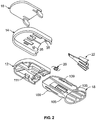
- a lens packaging system/lens loading system 10 in accordance with embodiments of the present invention includes a tray 12, a lid 14, a cover 16 and a loading tool 18.
- the tray 12 is configured to hold and store a foldable IOL 20 and a cartridge 22.
- the IOL 20 and cartridge 22 are held within the tray 12 via the lid 14, cover 16 and loading tool 18.
- the tray 12 also includes a lock (not shown) to secure the loading tool 18 during shipment and storage of the packaging system 10 and, thereby, prevent accidental activation of the loading tool 18.
- the packaging system 10 may be fabricated as a disposable, single-use component or a reusable, multi-use component.
- a variety of materials may be used to fabricate the tray 12, lid 14, cover 16 and loading tool 18 of the packaging system 10. These materials include, but are not limited to, plastics, metals (such as stainless steel, aluminum or titanium), ceramics and the like, including combinations thereof.
- the tray 12 is fabricated from polypropylene, and the lid 14 and loading tool 18 are fabricated from polycarbonate.
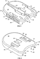
- the tray 12 in one embodiment of the packaging system 10, includes a distal end 24, a proximal end 26, a half-oval shaped top surface 28 and a sidewall 30.
- the distal end 24 of the tray 12 is rounded or curved to conform to the curved portion of the half-oval shaped top surface 28.
- the proximal end 26 of the tray 12 is also slightly curved or rounded and arches in the same direction as the distal end 24 of the tray 12.
- the proximal end 26 of the tray 12 is configured to accommodate the loading tool 18 of the packaging system 10, as described in further detail below.
- the distal and proximal ends 24, 26 of the tray 12 are arched in opposite directions. Furthermore, in certain embodiments, the distal and proximal ends 24, 26 of the tray 12 are angled to form a portion of a square, rectangle, triangle, quadrilateral, regular and/or irregular-shaped form.
- the top surface 28 of the tray 12 is generally planar or flat and includes one or more indentations and/or apertures 32, 33, 34 formed therein.
- the apertures 32 are disposed to either side of the top surface 28 and guide elements or posts, for aligning the lid 14 and/or loading tool 18 of the packaging system 10.
- the proximal-most apertures 33 are formed as two round holes in the top surface 28 of the tray. These apertures or holes 33 are configured to accommodate the alignment pins of the lid 14, as explained in further detail below.
- the center aperture 34 is configured to accommodate a lens 20 and lens cartridge 22, or similar lens holding and/or folding device.
- the center aperture 34 is approximately cross-shaped and includes a wide transverse slot 36 that intersects a narrow, elongate longitudinal slot 38 extending approximately from the proximal end 26 to the distal end 24 of the tray.
- the center aperture 34 further includes various chamfers and ridges within each slot 36, 38, which provide additional support and stability for the lens cartridge 22.
- each side-slot 40 Adjacent the center aperture 34 are two additional longitudinal side-slots 40.
- Each side-slot 40 is positioned on either side and in alignment with the wide transverse slot 36 of the center aperture 34.
- the side-slots 40 are approximately L-shaped and extend along the longitudinal axis near the side edges 42 of the tray 12.
- the side-slots 40 are designed to accommodate the guideposts of the cover 16, as described in further detail below.
- a sidewall 44 Integral with the top surface 28 of the tray 12 is a sidewall 44.
- the sidewall 44 extends along the perimeter of the top surface 28 and forms a hollow cavity beneath the top surface 28 of the tray 12.
- an opening 46 extends along a portion of the sidewall 44 located near the tray's proximal end 26.
- the opening 46 includes a first portion 48 and a second portion 50, wherein the first portion 48 of the opening 46 extends along a transverse, proximal section of the tray's sidewall 44.
- the second portion 50 of the opening 46 forms a longitudinal slot that is continuous with the first portion 48 and extends in a distal direction along the top surface 28 of the tray 12.
- the second portion 50 of the opening 46 merges with the central aperture 34 of the top surface 28.
- the opening 46 is configured to accommodate the loading tool 18 of the packaging system 10, as described in further detail below.
- the shape of the lid 14 is nearly identical to the shape of the tray 12.
- the sidewall 52 of the lid 14 does not extend completely around the perimeter of the lid's top surface 54 but, rather, includes a generally rectangular-shaped gap or aperture 56 near the proximal end 58 of the lid 14.
- each vertical edge 60 of the sidewall 52 that frames the gap or aperture 56 further includes at least one notch 62, which is continuous with the aperture 56 near the proximal end 58 of the lid 14.
- the lid's aperture and notches 56, 62 which are in direct alignment with the longitudinal slot 46 of the tray 12, are generally configured to accommodate the loading tool 18 when fully advanced during transfer of the IOL 20 into the cartridge 22.
- the proximal end of the lid's top surface 54 does not include apertures or indentations, as does the tray 12.
- the underside of the lid 14, near its proximal end may include one or more alignment pins 35. As explained above, these alignment pins 35 are configured to seat within the proximal-most apertures 33 of the tray 12 and, thereby, align and secure the lid 14 onto the tray 12 of the device 10.
- a central window 64 and indentations or tabs 66 are formed in the top surface 54 of the lid 14 and are generally aligned with the center aperture 34 of the tray 12.
- the central window 64 and tabs 66 allow portions of the cartridge 22 to be exposed, with the remaining portions of the cartridge 22 covered and secured by the lid 14.
- the lid 14 functions to secure the cartridge 22 within the packaging system 10 during storage and/or use of the system/device 10.
- the lid 14 of the packaging system 10 also includes one or more longitudinal side-slots 68.
- the side-slots 68 are positioned on either side of the indentations/tabs 66 and are designed to accommodate the guideposts of the cover 16.
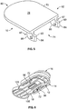
- the cover 16 makes reference to Figures 1 , 2 , 5, 6 and 7 .
- FIG. 5 depicts an embodiment of the cover 16 as used in the packaging system 10.
- the cover 16 preferably includes a generally planar or flat body 70 and two guideposts 72.
- the body 70 of the cover 16 further includes a top surface 78 and a bottom surface (not visible) that are shaped similar to the top surfaces 28, 54 of the tray 12 and lid 14.
- the body 70 is preferably configured in a half-oval shape that includes a rounded or curved distal end 80 and a relatively straight or linear proximal end 82.
- the body 70 of the cover 16 is sized to cover a substantial portion of the top surface 54 of the lid 14 and, in particular, at least a portion of the central window and indentations of the lid 14.
- the guideposts or guide elements 72 of the cover 16 may also be relatively planar or flat, but lie in vertical planes that are perpendicular to the plane of the cover's bottom surface.
- Each guidepost 72 is configured approximately in the shape of a quarter-circle and includes a first or longitudinal straight edge 83, a second or vertical straight edge 84 and a rounded edge 86.
- the first straight edge 83 of each guidepost 72 extends parallel to the bottom surface of the cover 16, while the second edge 84 is preferably positioned at approximately a ninety-degree angle from the first straight edge near the proximal end 82.
- a notch 85 is formed in the portion of the guidepost 72 where the first and second edges 84 intersect, the area around the notch 85 forming a type of neck or stem region 87.
- the stem region 87 is configured to seat within the narrow portion of the L-shaped slot 40 of the tray 12, as explained in further detail below.
- the remaining rounded edge 86 of the guidepost 72 connects the first and second edges 84 of the guidepost 72, thereby forming its generally quarter-circle shape.
- each guidepost 72 is sized to fit within the longitudinal side-slots 40, 68 of the tray 12 and lid 14.
- the guideposts 72 are generally parallel to each other and symmetrically positioned near the side edges of the cover 16, which generally correspond to the side edges of the lid 12 and tray 14.
- Figures 1 , 2 and 8 illustrate one embodiment of the loading tool 18, which includes a oval-shaped handle 92 in communication with a half-oval shaped slide 94.
- the handle 92 of the loading tool 18 includes a circular pushing surface 96 and a sidewall 98 that extends around the perimeter of the surface 96.
- the sidewall 98 provides additional structural support and gives added dimension to the handle 92 to enable a user to securely and controllably grip the loading tool 18 of the system.
- the half-oval shaped slide 94 is connected to the handle 92 of the loading tool 18 via the sidewall 98.
- the slide 94 of the loading tool 18 includes a generally planar or flat body 100 having a top surface and a bottom surface that are shaped similar to the top surfaces 28, 54 of the tray 12 and lid 14.
- the slide 94 of the loading tool 18 is configured in a half-oval shape that includes a generally rounded or curved distal end 102, two side-edges 104 and a proximal end 106 that follows the outline-shape of a portion of the sidewall 98.
- the slide 94 is sized to fit through the opening 46 of the sidewall 44 and within the tray 12 of the packaging system 10.
- one or more indentations 105 are located along the side-edges 104 and near the proximal end of the planar body 100 of the loading tool 18. These indentations 105 are configured to bypass the portion or section of the lid's sidewall 52 that surrounds or frames the lid's notches 62. In particular, during storage, the indentations 105 of the loading tool 18 are positioned proximal to and outside of the notches 62 of the lid 14. As such, the wider, non-indented section of the loading tool 18 is seated within the notches 62 during storage so that the lid 14 cannot be removed from the system or device 10. However, when the loading tool 18 is actuated or advanced distally, the indentations 105 fall into alignment with the notches 62, thereby allowing lid removal.
- each side-edge 104 of the slide 94 further includes one or more detents 109 which are configured to interact with the detent-slots 111 of the tray 12. Adjacent the detents 109 is a groove or slot 108 that extends along a longitudinal length of the slide 94. The grooves 108 are configured to accommodate the guideposts 72 of the cover 16 when the loading tool 18 is in a fully retracted or non-actuated position, as shown in Figure 6 , for example.
- grooves 108 also allow sufficient inward movement of the side-edges of the loading tool 18 to enable the detents 109 to pop out of the detent-slots 111 of tray 12 and travel along the inside sidewall of the tray 12 during device activation.
- the detents 109 of the loading tool 18 are seated within the detent-slots 111 of the tray 12.
- the guideposts 72 of the cover 16 are seated within the slots 68, 40, 108 of the lid 14, tray 12 and loading tool 18 and, in particular, are aligned with the detents 109 and detent-slots 111.
- the guideposts 72 prevent the detents 109 from causing the side-edges of the loading tool 18 to bow inward along the grooves 108 and from becoming dislodged from the detent-slots 111 of the tray 12.
- the guideposts 72 of the cover 16 serve, in part, to secure the system 10 during shipping and storage by preventing lateral distal advancement of the loading tool 18.
- the distal end 112 of the support member 110 includes a beveled and/or curved front edge formed to securely contact a portion of the IOL's perimeter and aid in advancing the IOL 20 into the cartridge 22.
- the distal end 112 further includes a groove located in the top surface of the support member 110 to securely hold a first or trailing haptic 113a of the IOL 20.
- the guide member 114 Distal to the support member 110 is a guide member 114.
- the guide member 114 includes a semi-flexible, U-shaped base 116 and a wedge-shaped holder 118.
- the forked end of the U-shaped base 116 extends longitudinally toward the proximal end 106 and is integrally formed with the body 100 of the push-rod 18.
- the wedge-shaped holder 118 Located along the distal end and perpendicular to the planar, U-shaped member 116 is the wedge-shaped holder 118.
- the wedge-shaped holder 118 includes a notched or grooved top surface 120 and a sloping front end 121.
- the grooved top surface 120 of the guide member 114 is configured to securely hold the second or leading haptic 113b of the IOL.
- the support member 110 and guide member 114 not only aid in advancing the IOL 20 into the cartridge 22, but also in controlling the IOL's rotational movement so that the IOL 20, and in particular the leading haptic 113b of the IOL 20, is correctly positioned within the cartridge 22.
- the U-shaped base 116 of the guide member 114 forms a central through-hole or window 122 in the body 100 of the loading tool 18.
- the window 122 enables a user of the device 10 to access a portion of the IOL 20 prior to IOL transfer into the cartridge 22.
- a user of the packaging system 10 may easily apply a lubricant, viscoelastic gel or viscoelastic surgical device (VSD) (not shown) to the IOL 20.
- VSD viscoelastic surgical device
- a VSD is injected into the eye to help maintain the shape of ocular structures and as a lubricant/coating to minimize trauma from surgical instruments and implants.
- viscoelastic may also be used with IOLs as a form of lubricant to aid in the passing of the IOL 20 into and through the cartridge 22 and to help prevent air bubbles from being delivered into the eye with the IOL 20, which would obstruct the surgeon's view during the IOL insertion procedure.
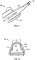
- FIGS 12 and 13 illustrate one preferred embodiment of the cartridge 22 for delivering an intraocular lens into the eye of a subject.
- the cartridge 22 includes an elongate tubular body 124 and two wings 126 longitudinally disposed to either side of the body 124 and formed along a proximal portion of the exterior sides of the body 124.
- the elongate body 124 is disposed along a longitudinal axis 127 and includes a distal end 128, a proximal end 130 and a tapering, longitudinal lumen 132 that extends along the axial length of body 124.
- the lumen 132 comprises a load chamber 131 disposed at the proximal end 130 of the body 124 for receiving or loading the IOL 20 and an aperture 133 disposed at the distal end 128 of the body 124 for delivering the IOL 20 into the eye of a subject.
- the lumen 132 or inside profile of the cartridge 22 is generally symmetrical about the longitudinal axis of the cartridge 22 and sized to accommodate the rod tip of the handpiece (not shown) during the insertion procedure.
- the aperture 133 and the cross-sectional shape of the lumen 132 near the aperture 133 generally comprises an upper portion 132a and a lower portion 132b.
- the upper portion 132a in cross-section is generally arcuate or dome shaped and has a width a
- the lower portion in cross-section is generally horizontally disposed and has a width b that is preferably greater than the width a.
- the bottom of lower portion 132b is preferably generally flat, as illustrated in Figure 14 , but may alternatively be arcuate in shape, for instance to increase or decrease the cross-sectional area of the lumen 132 at or near the aperture 133.
- the center of the IOL 20 is generally disposed in the upper portion 132a, while portions of the edges of the IOL 20 are substantially disposed in the lower portion 132b.
- the interior surface of the lumen 132 also includes one or more ribs 134 that extend substantially along the longitudinal length of the body 124.
- the triangular-shaped ribs 134 may extend from the loading area or proximal end 130 to the discharge area or distal end 128 of the cartridge 22.
- the ribs 134 function, at least in part, to fold or compress the edges of the IOL in a controlled manner toward the outer edges of the interior of the cartridge 22.
- the symmetry of the body 124 allows for even or uniform application of a coating to the interior surface simply using a spray apparatus.
- the cross-sectional area of the distal end of the lumen 132 is generally smaller than or reduced relative to the cross-sectional area of the proximal end of the lumen 132, as a result of the cartridge's tapered lumen 132.
- the taper of the lumen 132 aids in compressing or folding the IOL 20 as the IOL 20 passes through the lumen 132 of the cartridge 32 and into the patient's eye, as described in further detail below.
- the interior surface or inside edges of the cartridge 22 also may be configured to accommodate the shape of the IOL 20. This feature not only provides additional control during IOL transfer into the cartridge 22, but allows more efficient use of space to compress and guide the IOL 20 to the distal end 128 of the cartridge 22.
- the inside edges of the cartridge 22 are configured to mimic the shape of the AMO OptiEdge® IOL. The reduced friction between the IOL 20 and the interior wall of the cartridge 22 results in less force being needed to deform or compress the IOL 20 as it is pushed/advanced to the distal end 128 of the cartridge 22.
- a portion of the bottom surface 136 of the cartridge 22 includes an opening 138 which allows the wedge-shaped holder 118 of the loading tool 18 to extend therethrough and support the leading haptic 113b of the lens 20 during shipping and storage of the device 10 and loading of the IOL 20 into the cartridge 22.
- the opening 138 provides a means of guiding the leading haptic 113b in a forward direction toward the distal tip of the cartridge 22 when the IOL 20 is advanced into the cartridge 22.
- the opening 138 of the cartridge 22 may also be configured to allow a portion of the rod-tip of a handpiece to contact and/or push the IOL 20 through and out of the cartridge 22 during the insertion procedure.
- the opening 138 is preferably in the form of an elongated slot that is open at the proximal end 130 of the body 124, as illustrated in Figure 13 .
- the opening 138 may have other shapes, lengths, or aspect ratios depending upon the particular design requirements of the IOL 20, the cartridge 22, the loading tool 18, or the inserter and pushrod used to deliver the IOL 20 into the eye of a subject.
- each of the wings 126 formed along the exterior side near the proximal end of the cartridge 22 include a rectangular-shaped connecting rib 142 and finger grip 144.
- the connecting rib 142 extends along the longitudinal length of the proximal end 130 of the cartridge 22 and connects the finger grip 144 to the body 124 of the cartridge 22. Perpendicular to the connecting rib 142 is the rectangular-shaped finger grip 144.
- the finger grip 144 is illustrated as being rectangular in shape, it is understood that the finger grip 144 of the cartridge 22 can be configured in various shapes, sizes and textures, which allow a user of the device 10 to securely grasp the cartridge 22.
- the finger grip 144, connecting rib 142 and a portion of the cartridge body 124 form an exterior slot or groove 146 that is configured to mate with and snap into the distal end of a handpiece.
- the loading tool 18 and the cartridge 22 are mounted into the tray 12.
- the IOL 20 is preferably placed onto the IOL support member 110 of the loading tool 18 and disposed for loading into the load chamber 131.
- the lid 14 and the cover 16 are preferably placed over the tray 12 in order to protect the IOL 20 and prevent premature loading of the IOL 20 into the load chamber 131.
- a viscoelastic or other substance may be applied to both the IOL 20 and cartridge 22 of the device 10.
- the window 122 in the loading tool 18 enables a user to apply viscoelastic to the IOL 20.
- the opening 138 in the cartridge 22 also enables a user of the device 10 to easily administer viscoelastic into the cartridge 22.
- the viscoelastic lubricates the surfaces of the cartridge 22 and IOL 20, thereby mitigating any tearing of the IOL 20 as it travels through the cartridge 22 and reducing the incidence of tissue trauma to the eye.
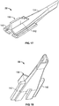
- FIG. 17-19 an alternate embodiment of the cartridge 22 is illustrated in which the finger grips 144 of the wings 126 have been removed and a holding handle 150 has been added to top, exterior surface near the proximal end 130 of the cartridge 22.
- the cartridge 22 illustrated in Figure 17 is shown mounted in the tray 12 along with the loading tool 18 and the IOL 20.
- the cartridge 22 is used in conjunction with a handpiece to deliver the IOL 20 into the eye of a subject.
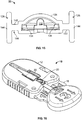
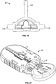
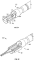
- Figures 21-24 illustrate a handpiece 140 which is configured to hold the cartridge 22, preferably after the loading tool 18 has been used to mount the IOL 20 into longitudinal lumen 132.
- an insertion system 160 for delivering the intraocular lens 20 into the eye of a subject comprises the cartridge 22 and an inserter 161.
- the inserter 161 comprises a handpiece 162 and a pushrod 164 with a tip 168 having a saddle 170.
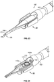
- the saddle 170 preferably has a smaller diameter than the remainder of the pushrod 164, such that a ledge 171 is formed between the saddle 170 and the remaining portions of the pushrod 164, as illustrated in Figures 21 and 23 .
- the opening 138 on the bottom surface 136 of the cartridge 22 is disposed to permit passage of at least a portion of the tip 168 when cartridge is placed onto the handpiece 162 from above the handpiece 162.
- the handpiece 162 further comprises a raised platform 172 disposed below pushrod 164, the raised platform 172 being sized to fit within the opening 138.
- the platform 172 may be configured to fit tightly within the opening 138, for instance, to aid in securely maintaining the cartridge 22 when attached to the handpiece 162; however, a tight fit between the opening 138 and the platform 172 is not essential.
- the insertion system 160 further comprises at least a portion of the lens packaging system/lens loading system 10 for storing the IOL 20 and/or for placing the IOL 20 in the cartridge 22.
- the system 160 may include the tray 12 and the loading tool 18.
- the system 160 may include the lid 14 and the cover 16, for instance, in order to protect the IOL 20 and prevent premature loading of the IOL 20 into the load chamber 131.
- the IOL 20 is preferable place inside the packaging system 10 prior to storage and/or shipment to a customer or user.
- at least portions of the system 10, for example the tray 12 and the loading tool 18, may be stored or shipped as separate parts. A practitioner may then use the portions of the packaging system 10 to load the IOL 20 inside the load chamber 133 of the cartridge 22 just prior to placing the IOL inside an eye using the handpiece 162.
- the distal end of the handpiece 140 includes two rails or side-edges 148 having slightly curved proximal and distal ends.
- the rails 148 are sized and shaped to fit securely within the grooves 146 of the cartridge 22, with the distal ends of the rails 148 having a greater curved depth than the proximal ends.
- the distal ends of the cartridge grooves 146 are first slid into the curved distal ends of the rails 148.
- the proximal ends of the grooves 146 are then inserted downward and preferably snapped into the curved proximal ends of the rails 148.
- the snap-fit between the grooves 146 and the rails 148 keep the cartridge 22 securely within the handpiece 140 during the lens delivery procedure.
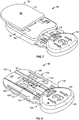
- the packaging system 10 is typically supplied to an end-user or surgeon with a lens cartridge 22 and IOL 20 pre-loaded within the tray 12.
- Figures 16 and 20 illustrate embodiments of the packaging system as supplied to the end user with the cover 16 and lid 14 removed to clearly show the lens 20 and cartridge 22 within the device 10.
- the packaging system 10 may only include the IOL 20, thereby allowing the user of the device 10 to supply the cartridge 22.
- the tray 12 of the device 10 Prior to use, the tray 12 of the device 10 is covered with the lid 14 and the loading tool 18 is a retracted or partially inserted position within the opening 46 of the tray 12.
- the cover 16 is secured to the lid 14, tray 12 and loading tool 18, via the guide elements 72 and slots 40, 68, 108, to prevent inadvertent or unintentional activation of the system 10.
- the guideposts or vertical members 72 of the cover 16 block further distal advancement of the loading tool 18, and its support member 110, until the cover 16 is removed from the system 10.
- the cover 16 is removed to expose the top surface 54 of the lid 14.
- the lid 14 is fabricated from a clear material to allow the user of the device 10 to inspect the system 10, particularly the lens cartridge 22 and IOL 20, prior to use to ensure that none of the components are damaged. Removal of the cover 16 also exposes the central window 64 of the lid 14 and, thereby, a portion of the lens cartridge 22. Viscoelastic fluid is applied to the cartridge 22 and/or the IOL 22 through the opening 138 and window 122, respectively, prior to device activation.
- a user may simply grasp the handle 92 of the loading tool 18 using, for example, his/her thumb and fore-finger, and push the loading tool 18 in a distal direction. Longitudinal sliding movement of the loading tool 18 causes the distal tip 112 of the support member 110 to push the IOL 20 along the longitudinal slot of the tray 12 and into the lumen 132 of the cartridge 22.
- the lid 14 of the packaging system 10 is then removed.
- the loading tool 18 is proximally retracted to release the loaded cartridge 22 from the loading tool 18 and the loaded cartridge 22 is then removed from the packaging system.
- the user may easily transfer the cartridge 22 with its loaded IOL 20 to the inserter 161 for delivery of the IOL 20 into a patient's eye.
- the packaging system 10 may be used to simplify the removal and transfer of the IOL 20 to the IOL insertion system 160.
- the packaging device 10 enables a user to easily load an IOL 20 into a cartridge 22 without requiring the use of forceps.
- the configuration of the cartridge 22 also allows a user to fold and/or compress the IOL 20 during IOL delivery into the eye without damaging the IOL 20 and/or compromising IOL sterility.
- the related methods of operation minimize and/or eliminate the potential of damaging the IOL 20 during unpackaging, folding, transfer and/or loading procedures.
- the device 10 and its method of use provide repeatable and consistent loading (e.g., with respect to position and rotation) of the IOL 20 into the cartridge 22.
- a method of inserting the IOL 20 comprises providing the cartridge 22 and providing the handpiece 140 with the pushrod 164 having the saddle 170 in the tip 168. The method further comprises disposing the cartridge 22 above the handpiece 140 and attaching the cartridge 22 onto the handpiece 140 from above the handpiece 140. While attaching the cartridge 22, the method also includes disposing the tip 168 such that the opening 138 permits passage of at least a portion of the tip 168, for instance, as illustrated in Figures 21 and 24 .
- the method may further comprises loading the IOL 20 in the cartridge 22, for instance by using the loading tool 18, as discussed above herein.
- the IOL 20 is preferably placed in the cartridge 22 prior to attaching the cartridge 22 onto the handpiece 162.
- the IOL 20 is loaded into the load chamber such that at least a portion of at least one of the haptics 113a, 113b is disposed above at least a portion of the pushrod, as illustrated in Figure 24 .
- the IOL 20 is loaded into the load chamber 22 such at least a portion of an optic body 174 of the IOL 20 is disposed above or draped over the saddle 170 of the tip 168, for instance, as illustrated in Figures 24 and 27 .
- the method comprises advancing the IOL 20 along the lumen 132 and into the eye of a subject at least in part by engaging an edge of the optic body 174 of the IOL 20 with the ledge 171 at the tip 168 of the pushrod 164.
- the ledge 171 may be used to help prevent the pushrod 164 from moving too far into the optic body 174, thereby advantageously preventing the pushrod 164 from damaging the optic body 174.
- the ledge 171 may also be used to more evenly distribute the force produced by the pushrod 164 around the edge of the optic body 174.
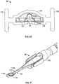
- the IOL 20 is disposed in the load chamber 131 in a substantially flat and substantially unstressed state, as illustrated Figures 24 and 25 .
- the optic body 174 of the IOL 20 is folded or squeezed such that the central portions of the IOL 20 fill the upper portion 132b of the lumen 132, as illustrated in Figure 26 .
- the edges of the optic body 174 of the IOL 20 largely are contained within the lower portion 132a of the lumen, thereby advantageously allowing the orientation of the IOL 20 to be maintained as it advances down the lumen 132 and into the eye of the subject. In certain embodiments, as illustrated in Figure 27 , this allows the IOL 20 to exit the aperture 133 of the lumen 132 in substantially the same orientation as it had when it was in the load chamber 131.
Landscapes
- Health & Medical Sciences (AREA)
- Ophthalmology & Optometry (AREA)
- Cardiology (AREA)
- Oral & Maxillofacial Surgery (AREA)
- Transplantation (AREA)
- Engineering & Computer Science (AREA)
- Biomedical Technology (AREA)
- Heart & Thoracic Surgery (AREA)
- Vascular Medicine (AREA)
- Life Sciences & Earth Sciences (AREA)
- Animal Behavior & Ethology (AREA)
- General Health & Medical Sciences (AREA)
- Public Health (AREA)
- Veterinary Medicine (AREA)
- Prostheses (AREA)
Claims (10)
- Patrone (22) zur Abgabe einer Intraokularlinse (20) in das Auge eines Subjekts, umfassend:einen Körper (124), der entlang einer Längsachse (127) angeordnet ist und ein distales Ende (128) und ein proximales Ende (130) aufweist; undein konisches Lumen (132), das entlang der Längsachse (127) angeordnet ist und eine Öffnung (133) an dem distalen Ende (128) des Körpers (124) aufweist; undwobei mindestens ein Abschnitt des konischen Lumens (132) aus einem ersten Abschnitt (132a) und einem zweiten Abschnitt (132b) besteht,gekennzeichnet dadurch, dass:der erste Abschnitt (132a) eine erste Breite (a) und einen Querschnitt aufweist, der im Allgemeinen gekrümmt ist;der zweite Abschnitt (132b) einen Querschnitt aufweist, der im Allgemeinen horizontal angeordnet ist und eine zweite Breite (b) aufweist, die größer ist als die erste Breite (a); undder erste und der zweite Abschnitt derart angeordnet sind, dass, wenn das Lumen verwendet wird, um eine Intraokularlinse abzugeben, eine Mitte der Intraokularlinse im Allgemeinen in dem ersten Abschnitt angeordnet ist, während die Abschnitte der Ränder der Intraokularlinse im Wesentlichen in dem zweiten Abschnitt angeordnet sind.
- Patrone nach Anspruch 1, ferner umfassend Flügel (126), die in Längsrichtung auf beiden Seiten des Körpers (124) angeordnet sind.
- Patrone nach Anspruch 1 oder Anspruch 2, wobei der Körper (124) ferner eine Unterseite (136) mit einer Öffnung (138) umfasst, die entlang der Längsachse (127) angeordnet ist.
- Patrone nach einem der Ansprüche 1 bis 3, wobei die Öffnung (138) einen Längsschlitz umfasst, der an dem proximalen Ende des Körpers offen ist.
- Patrone nach einem der Ansprüche 1 bis 4, wobei die Öffnung (138) dazu angeordnet ist, eine Spitze einer Druckstange (164) eines Handstücks der Einführvorrichtung (140; 162) aufzunehmen.
- Einführsystem (160) zur Abgabe einer Intraokularlinse (20) in das Auge eines Subjekts, umfassend:eine Patrone nach einem der Ansprüche 1 bis 5, wobei die Patrone aufweist:eine Ladekammer (131) zum Aufnehmen einer Intraokularlinse (20);eine Unterseite (136) mit einer Öffnung (138), die entlang der Längsachse angeordnet ist; undein Handstück (140; 162), das eine Druckstange (164) mit einer Spitze (168) umfasst, die einen Sattel (170) aufweist;wobei die Öffnung (138) dazu angeordnet ist, den Durchgang von mindestens einem Abschnitt der Spitze (168) zu erlauben, wenn die Patrone (22) von oberhalb des Handstücks auf das Handstück (140; 162) platziert wird, unddie Patrone dazu ausgelegt ist, zu ermöglichen, dass die Spitze die Intraokularlinse kontaktiert und die Intraokularlinse während des Einführvorgangs durch die Patrone hindurch und aus ihr heraus drückt.
- Einführsystem nach Anspruch 6, ferner umfassend ein Verpackungssystem (10) zum Platzieren einer Intraokularlinse (20) in der Patrone (22).
- Einführsystem nach Anspruch 7, wobei das Verpackungssystem (10) eine Ablage (12) und ein Beladungswerkzeug (18) umfasst.
- Einführsystem nach Anspruch 8, wobei das Verpackungssystem (10) ferner einen Deckel (14) und eine Abdeckung (16) umfasst.
- Einführsystem nach einem der Ansprüche 6 bis 9, wobei das Handstück (162) ferner eine erhöhte Plattform (172) umfasst, die unterhalb der Druckstange (164) angeordnet ist, wobei die erhöhte Plattform so groß gestaltet ist, dass sie in die Öffnung passt.
Priority Applications (1)
| Application Number | Priority Date | Filing Date | Title |
|---|---|---|---|
| EP19177717.6A EP3552582A1 (de) | 2004-03-02 | 2005-03-02 | Vorrichtungen und verfahren zur aufbewahrung, ladung und ausgabe einer intraokularlinse |
Applications Claiming Priority (2)
| Application Number | Priority Date | Filing Date | Title |
|---|---|---|---|
| US54989904P | 2004-03-02 | 2004-03-02 | |
| PCT/US2005/006892 WO2005084588A1 (en) | 2004-03-02 | 2005-03-02 | Devices and methods for storing, loading, and delivering an intraocular lens |
Related Child Applications (2)
| Application Number | Title | Priority Date | Filing Date |
|---|---|---|---|
| EP19177717.6A Division-Into EP3552582A1 (de) | 2004-03-02 | 2005-03-02 | Vorrichtungen und verfahren zur aufbewahrung, ladung und ausgabe einer intraokularlinse |
| EP19177717.6A Division EP3552582A1 (de) | 2004-03-02 | 2005-03-02 | Vorrichtungen und verfahren zur aufbewahrung, ladung und ausgabe einer intraokularlinse |
Publications (2)
| Publication Number | Publication Date |
|---|---|
| EP1720490A1 EP1720490A1 (de) | 2006-11-15 |
| EP1720490B1 true EP1720490B1 (de) | 2019-07-31 |
Family
ID=34919555
Family Applications (2)
| Application Number | Title | Priority Date | Filing Date |
|---|---|---|---|
| EP19177717.6A Pending EP3552582A1 (de) | 2004-03-02 | 2005-03-02 | Vorrichtungen und verfahren zur aufbewahrung, ladung und ausgabe einer intraokularlinse |
| EP05735577.8A Active EP1720490B1 (de) | 2004-03-02 | 2005-03-02 | Vorrichtungen zur aufbewahrung, ladung und abgabe einer intraokularlinse |
Family Applications Before (1)
| Application Number | Title | Priority Date | Filing Date |
|---|---|---|---|
| EP19177717.6A Pending EP3552582A1 (de) | 2004-03-02 | 2005-03-02 | Vorrichtungen und verfahren zur aufbewahrung, ladung und ausgabe einer intraokularlinse |
Country Status (6)
| Country | Link |
|---|---|
| EP (2) | EP3552582A1 (de) |
| JP (1) | JP4749413B2 (de) |
| AU (1) | AU2005218601B2 (de) |
| BR (1) | BRPI0508316B8 (de) |
| CA (1) | CA2557967C (de) |
| WO (1) | WO2005084588A1 (de) |
Families Citing this family (55)
| Publication number | Priority date | Publication date | Assignee | Title |
|---|---|---|---|---|
| FR2833154B1 (fr) | 2001-12-12 | 2004-11-19 | Ioltechnologie Production | Cassette et injecteur de lentille intraoculaire souple et procede d'injection de telles lentilles |
| US10045844B2 (en) | 2002-02-02 | 2018-08-14 | Powervision, Inc. | Post-implant accommodating lens modification |
| US8328869B2 (en) | 2002-12-12 | 2012-12-11 | Powervision, Inc. | Accommodating intraocular lenses and methods of use |
| US7217288B2 (en) | 2002-12-12 | 2007-05-15 | Powervision, Inc. | Accommodating intraocular lens having peripherally actuated deflectable surface and method |
| US8361145B2 (en) | 2002-12-12 | 2013-01-29 | Powervision, Inc. | Accommodating intraocular lens system having circumferential haptic support and method |
| US10835373B2 (en) | 2002-12-12 | 2020-11-17 | Alcon Inc. | Accommodating intraocular lenses and methods of use |
| AU2004219674A1 (en) | 2003-03-06 | 2004-09-23 | Powervision, Inc. | Adaptive optic lens and method of making |
| US9872763B2 (en) | 2004-10-22 | 2018-01-23 | Powervision, Inc. | Accommodating intraocular lenses |
| WO2006070628A1 (ja) | 2004-12-27 | 2006-07-06 | Hoya Corporation | 眼内レンズ移植装置 |
| JP5221949B2 (ja) | 2005-01-26 | 2013-06-26 | Hoya株式会社 | 眼内レンズ挿入用器具 |
| JP4836046B2 (ja) | 2005-02-24 | 2011-12-14 | Hoya株式会社 | 眼内レンズ挿入器具 |
| WO2007037223A1 (ja) | 2005-09-28 | 2007-04-05 | Hoya Corporation | 眼内レンズ挿入用器具 |
| JP4520390B2 (ja) | 2005-09-29 | 2010-08-04 | 株式会社ニデック | 眼内レンズ挿入システム |
| JP4767671B2 (ja) * | 2005-12-02 | 2011-09-07 | 株式会社ニデック | 眼内レンズ挿入システム |
| JP4877643B2 (ja) | 2005-12-08 | 2012-02-15 | Hoya株式会社 | 眼内レンズ挿入用器具 |
| JP4927473B2 (ja) * | 2006-08-11 | 2012-05-09 | 興和株式会社 | 眼内レンズの挿入器具 |
| US7879090B2 (en) | 2006-12-13 | 2011-02-01 | Bausch & Lomb Incorporated | Intraocular lens injector apparatus and methods of use |
| CN101678149B (zh) | 2007-02-21 | 2013-07-17 | 力景公司 | 适用于眼用装置的聚合材料及其制造方法 |
| WO2008149794A1 (ja) | 2007-05-30 | 2008-12-11 | Hoya Corporation | 眼内レンズ挿入器具 |
| WO2008149795A1 (ja) | 2007-05-30 | 2008-12-11 | Hoya Corporation | 眼内レンズ挿入器具 |
| JP5086713B2 (ja) | 2007-07-11 | 2012-11-28 | Hoya株式会社 | 眼内レンズ挿入器具 |
| US8668734B2 (en) | 2010-07-09 | 2014-03-11 | Powervision, Inc. | Intraocular lens delivery devices and methods of use |
| US8314927B2 (en) | 2007-07-23 | 2012-11-20 | Powervision, Inc. | Systems and methods for testing intraocular lenses |
| JP5346022B2 (ja) | 2007-07-23 | 2013-11-20 | パワーヴィジョン・インコーポレーテッド | 調節眼内レンズおよび使用方法 |
| US8968396B2 (en) | 2007-07-23 | 2015-03-03 | Powervision, Inc. | Intraocular lens delivery systems and methods of use |
| EP2178464B1 (de) | 2007-07-23 | 2013-08-21 | PowerVision, Inc. | Linseneinführsystem und Verfahren |
| US8702794B2 (en) * | 2008-04-28 | 2014-04-22 | Abbott Medical Optics Inc. | Back loaded IOL insertion cartridge |
| JP5254669B2 (ja) * | 2008-06-05 | 2013-08-07 | Hoya株式会社 | 眼内レンズ挿入器具及びカートリッジ |
| JP5470753B2 (ja) | 2008-06-17 | 2014-04-16 | Hoya株式会社 | 眼内レンズ挿入器具 |
| JP5323420B2 (ja) | 2008-08-21 | 2013-10-23 | Hoya株式会社 | 眼内レンズ挿入器具 |
| JP5416379B2 (ja) | 2008-09-04 | 2014-02-12 | Hoya株式会社 | 眼内レンズ挿入器具 |
| FR2935606B1 (fr) * | 2008-09-11 | 2010-09-03 | Patrick Meunier | Systeme d'injection d'une lentille intraoculaire comprenant un injecteur avec une cartouche et un dispositif de chargement. |
| CN102231970B (zh) * | 2008-12-01 | 2014-07-30 | 兴和株式会社 | 眼内透镜插入器具 |
| SG172876A1 (en) | 2009-01-07 | 2011-08-29 | Hoya Corp | Intraocular lens insertion device |
| US10299913B2 (en) | 2009-01-09 | 2019-05-28 | Powervision, Inc. | Accommodating intraocular lenses and methods of use |
| GB2472872B (en) * | 2009-08-18 | 2014-12-31 | Carl Zeiss Meditec Sas | Holding device for an intraocular lens, packaging and transport means for an intraocular lens and injector device for an intraocular lens. |
| US8447086B2 (en) | 2009-08-31 | 2013-05-21 | Powervision, Inc. | Lens capsule size estimation |
| WO2011106435A2 (en) | 2010-02-23 | 2011-09-01 | Powervision, Inc. | Fluid for accommodating intraocular lenses |
| US9326847B2 (en) | 2010-04-08 | 2016-05-03 | Hoya Corporation | Ocular implant insertion apparatus and methods |
| JP5511530B2 (ja) | 2010-06-10 | 2014-06-04 | Hoya株式会社 | 眼内レンズ挿入装置 |
| CN103547239B (zh) * | 2010-12-20 | 2015-09-16 | 诺华公司 | 眼内晶状体传送盒 |
| JP6071995B2 (ja) | 2011-03-24 | 2017-02-01 | パワーヴィジョン・インコーポレーテッド | 眼内レンズ装填システムおよび使用方法 |
| US8690941B2 (en) * | 2011-10-04 | 2014-04-08 | Novartis Ag | Intraocular lens surgical system and method |
| US10433949B2 (en) | 2011-11-08 | 2019-10-08 | Powervision, Inc. | Accommodating intraocular lenses |
| WO2014104271A1 (ja) * | 2012-12-27 | 2014-07-03 | 参天製薬株式会社 | 眼内レンズ用インジェクタ |
| JP6717740B2 (ja) | 2013-03-15 | 2020-07-01 | パワーヴィジョン・インコーポレーテッド | 眼内レンズの収容および載置装置ならびにその使用方法 |
| JP6646987B2 (ja) | 2015-09-16 | 2020-02-14 | Hoya株式会社 | 眼内レンズ挿入器具 |
| WO2017047714A1 (ja) | 2015-09-16 | 2017-03-23 | Hoya株式会社 | 眼内レンズ挿入器具 |
| CA3001477A1 (en) | 2015-11-06 | 2017-05-11 | Powervision, Inc. | Accommodating intraocular lenses and methods of manufacturing |
| KR102431211B1 (ko) | 2016-06-28 | 2022-08-09 | 호야 가부시키가이샤 | 안내 렌즈 삽입기 |
| KR102445286B1 (ko) * | 2016-07-07 | 2022-09-19 | 이올루션 게엠베하 | 안구내 렌즈를 이식하는 인젝터를 위한 카트리지 |
| WO2018151141A1 (ja) * | 2017-02-15 | 2018-08-23 | 参天製薬株式会社 | 眼内レンズ用インジェクタ |
| WO2019130029A1 (en) | 2017-12-28 | 2019-07-04 | Medicontour Medical Engineering Ltd. | Lens case for intraocular lenses with haptics |
| US11660182B2 (en) | 2019-10-04 | 2023-05-30 | Alcon Inc. | Adjustable intraocular lenses and methods of post-operatively adjusting intraocular lenses |
| CN115737269B (zh) * | 2022-11-17 | 2023-07-21 | 齐齐哈尔建华医院有限责任公司 | 一种眼科器件植入器 |
Family Cites Families (7)
| Publication number | Priority date | Publication date | Assignee | Title |
|---|---|---|---|---|
| US6056757A (en) * | 1992-09-30 | 2000-05-02 | Staar Surgical Company, Inc. | Implantation device with deformable nozzle tip for implanting a deformable intraocular lens |
| US6406481B2 (en) * | 1992-09-30 | 2002-06-18 | Starr Surgical Company, Inc. | Method preloading a deformable intraocular lens into injecting apparatus for storage and/or shipment |
| US6447520B1 (en) * | 2001-03-19 | 2002-09-10 | Advanced Medical Optics, Inc. | IOL insertion apparatus with IOL engagement structure and method for using same |
| FR2789890B1 (fr) * | 1999-02-22 | 2002-01-18 | Lab Contactologie Appl Lca | Dispositif pour l'injection d'une lentille intra-oculaire en matiere souple |
| FR2820633B1 (fr) * | 2001-02-13 | 2003-08-15 | Biotech | Dispositif et procede d'injection de lentille intraoculaire |
| JP2002355268A (ja) * | 2001-06-01 | 2002-12-10 | Nidek Co Ltd | 眼内レンズ挿入器具 |
| WO2005070341A1 (ja) * | 2004-01-27 | 2005-08-04 | Hoya Corporation | 眼内レンズ挿入装置及びそのカートリッジ |
-
2005
- 2005-03-02 AU AU2005218601A patent/AU2005218601B2/en not_active Ceased
- 2005-03-02 EP EP19177717.6A patent/EP3552582A1/de active Pending
- 2005-03-02 EP EP05735577.8A patent/EP1720490B1/de active Active
- 2005-03-02 BR BRPI0508316A patent/BRPI0508316B8/pt not_active IP Right Cessation
- 2005-03-02 WO PCT/US2005/006892 patent/WO2005084588A1/en not_active Application Discontinuation
- 2005-03-02 JP JP2007501971A patent/JP4749413B2/ja not_active Expired - Fee Related
- 2005-03-02 CA CA2557967A patent/CA2557967C/en active Active
Non-Patent Citations (1)
| Title |
|---|
| None * |
Also Published As
| Publication number | Publication date |
|---|---|
| WO2005084588A1 (en) | 2005-09-15 |
| CA2557967A1 (en) | 2005-09-15 |
| AU2005218601B2 (en) | 2012-01-19 |
| EP1720490A1 (de) | 2006-11-15 |
| JP2007526091A (ja) | 2007-09-13 |
| BRPI0508316B1 (pt) | 2018-06-19 |
| BRPI0508316B8 (pt) | 2021-06-22 |
| BRPI0508316A (pt) | 2007-07-24 |
| JP4749413B2 (ja) | 2011-08-17 |
| AU2005218601A1 (en) | 2005-09-15 |
| EP3552582A1 (de) | 2019-10-16 |
| CA2557967C (en) | 2013-12-10 |
Similar Documents
| Publication | Publication Date | Title |
|---|---|---|
| EP1720490B1 (de) | Vorrichtungen zur aufbewahrung, ladung und abgabe einer intraokularlinse | |
| US7458976B2 (en) | Devices and methods for storing, loading, and delivering an intraocular lens | |
| US8475527B2 (en) | Intraocular lens and cartridge packaging with lens-loading function | |
| US9339374B2 (en) | Intraocular lens insertion apparatus and lens case | |
| US20080147082A1 (en) | Injector apparatus for use with intraocular lenses and methods of use | |
| US20080147080A1 (en) | Injector apparatus for use with intraocular lenses and methods of use | |
| AU2012202321B2 (en) | Devices and methods for storing, loading, and delivering an intraocular lens | |
| AU2011203121B2 (en) | Intraocular lens and cartridge packaging with lens-loading function |
Legal Events
| Date | Code | Title | Description |
|---|---|---|---|
| PUAI | Public reference made under article 153(3) epc to a published international application that has entered the european phase |
Free format text: ORIGINAL CODE: 0009012 |
|
| 17P | Request for examination filed |
Effective date: 20060825 |
|
| AK | Designated contracting states |
Kind code of ref document: A1 Designated state(s): AT BE BG CH CY CZ DE DK EE ES FI FR GB GR HU IE IS IT LI LT LU MC NL PL PT RO SE SI SK TR |
|
| RIN1 | Information on inventor provided before grant (corrected) |
Inventor name: COLE, MARK, S. Inventor name: OTT, ROBERT, D. Inventor name: PETERSON, ROD, T. |
|
| DAX | Request for extension of the european patent (deleted) | ||
| 17Q | First examination report despatched |
Effective date: 20090706 |
|
| RAP1 | Party data changed (applicant data changed or rights of an application transferred) |
Owner name: ABBOTT MEDICAL OPTICS INC. |
|
| RAP1 | Party data changed (applicant data changed or rights of an application transferred) |
Owner name: ABBOTT MEDICAL OPTICS INC. |
|
| STAA | Information on the status of an ep patent application or granted ep patent |
Free format text: STATUS: EXAMINATION IS IN PROGRESS |
|
| GRAP | Despatch of communication of intention to grant a patent |
Free format text: ORIGINAL CODE: EPIDOSNIGR1 |
|
| STAA | Information on the status of an ep patent application or granted ep patent |
Free format text: STATUS: GRANT OF PATENT IS INTENDED |
|
| INTG | Intention to grant announced |
Effective date: 20180507 |
|
| RAP1 | Party data changed (applicant data changed or rights of an application transferred) |
Owner name: JOHNSON & JOHNSON SURGICAL VISION, INC. |
|
| GRAJ | Information related to disapproval of communication of intention to grant by the applicant or resumption of examination proceedings by the epo deleted |
Free format text: ORIGINAL CODE: EPIDOSDIGR1 |
|
| GRAP | Despatch of communication of intention to grant a patent |
Free format text: ORIGINAL CODE: EPIDOSNIGR1 |
|
| INTG | Intention to grant announced |
Effective date: 20181119 |
|
| GRAJ | Information related to disapproval of communication of intention to grant by the applicant or resumption of examination proceedings by the epo deleted |
Free format text: ORIGINAL CODE: EPIDOSDIGR1 |
|
| STAA | Information on the status of an ep patent application or granted ep patent |
Free format text: STATUS: EXAMINATION IS IN PROGRESS |
|
| GRAP | Despatch of communication of intention to grant a patent |
Free format text: ORIGINAL CODE: EPIDOSNIGR1 |
|
| STAA | Information on the status of an ep patent application or granted ep patent |
Free format text: STATUS: GRANT OF PATENT IS INTENDED |
|
| INTC | Intention to grant announced (deleted) | ||
| INTG | Intention to grant announced |
Effective date: 20190329 |
|
| GRAS | Grant fee paid |
Free format text: ORIGINAL CODE: EPIDOSNIGR3 |
|
| GRAA | (expected) grant |
Free format text: ORIGINAL CODE: 0009210 |
|
| STAA | Information on the status of an ep patent application or granted ep patent |
Free format text: STATUS: THE PATENT HAS BEEN GRANTED |
|
| REG | Reference to a national code |
Ref country code: DE Ref legal event code: R081 Ref document number: 602005056087 Country of ref document: DE Owner name: JOHNSON & JOHNSON SURGICAL VISION, INC., IRVIN, US Free format text: FORMER OWNER: ADVANCED MEDICAL OPTICS, INC., SANTA ANA, CALIF., US |
|
| AK | Designated contracting states |
Kind code of ref document: B1 Designated state(s): AT BE BG CH CY CZ DE DK EE ES FI FR GB GR HU IE IS IT LI LT LU MC NL PL PT RO SE SI SK TR |
|
| REG | Reference to a national code |
Ref country code: CH Ref legal event code: EP Ref country code: GB Ref legal event code: FG4D |
|
| REG | Reference to a national code |
Ref country code: DE Ref legal event code: R096 Ref document number: 602005056087 Country of ref document: DE |
|
| REG | Reference to a national code |
Ref country code: AT Ref legal event code: REF Ref document number: 1160135 Country of ref document: AT Kind code of ref document: T Effective date: 20190815 |
|
| REG | Reference to a national code |
Ref country code: IE Ref legal event code: FG4D |
|
| REG | Reference to a national code |
Ref country code: NL Ref legal event code: FP |
|
| REG | Reference to a national code |
Ref country code: LT Ref legal event code: MG4D |
|
| REG | Reference to a national code |
Ref country code: AT Ref legal event code: MK05 Ref document number: 1160135 Country of ref document: AT Kind code of ref document: T Effective date: 20190731 |
|
| PG25 | Lapsed in a contracting state [announced via postgrant information from national office to epo] |
Ref country code: FI Free format text: LAPSE BECAUSE OF FAILURE TO SUBMIT A TRANSLATION OF THE DESCRIPTION OR TO PAY THE FEE WITHIN THE PRESCRIBED TIME-LIMIT Effective date: 20190731 Ref country code: LT Free format text: LAPSE BECAUSE OF FAILURE TO SUBMIT A TRANSLATION OF THE DESCRIPTION OR TO PAY THE FEE WITHIN THE PRESCRIBED TIME-LIMIT Effective date: 20190731 Ref country code: BG Free format text: LAPSE BECAUSE OF FAILURE TO SUBMIT A TRANSLATION OF THE DESCRIPTION OR TO PAY THE FEE WITHIN THE PRESCRIBED TIME-LIMIT Effective date: 20191031 Ref country code: SE Free format text: LAPSE BECAUSE OF FAILURE TO SUBMIT A TRANSLATION OF THE DESCRIPTION OR TO PAY THE FEE WITHIN THE PRESCRIBED TIME-LIMIT Effective date: 20190731 Ref country code: PT Free format text: LAPSE BECAUSE OF FAILURE TO SUBMIT A TRANSLATION OF THE DESCRIPTION OR TO PAY THE FEE WITHIN THE PRESCRIBED TIME-LIMIT Effective date: 20191202 Ref country code: AT Free format text: LAPSE BECAUSE OF FAILURE TO SUBMIT A TRANSLATION OF THE DESCRIPTION OR TO PAY THE FEE WITHIN THE PRESCRIBED TIME-LIMIT Effective date: 20190731 |
|
| PG25 | Lapsed in a contracting state [announced via postgrant information from national office to epo] |
Ref country code: IS Free format text: LAPSE BECAUSE OF FAILURE TO SUBMIT A TRANSLATION OF THE DESCRIPTION OR TO PAY THE FEE WITHIN THE PRESCRIBED TIME-LIMIT Effective date: 20191130 Ref country code: ES Free format text: LAPSE BECAUSE OF FAILURE TO SUBMIT A TRANSLATION OF THE DESCRIPTION OR TO PAY THE FEE WITHIN THE PRESCRIBED TIME-LIMIT Effective date: 20190731 Ref country code: GR Free format text: LAPSE BECAUSE OF FAILURE TO SUBMIT A TRANSLATION OF THE DESCRIPTION OR TO PAY THE FEE WITHIN THE PRESCRIBED TIME-LIMIT Effective date: 20191101 |
|
| PG25 | Lapsed in a contracting state [announced via postgrant information from national office to epo] |
Ref country code: TR Free format text: LAPSE BECAUSE OF FAILURE TO SUBMIT A TRANSLATION OF THE DESCRIPTION OR TO PAY THE FEE WITHIN THE PRESCRIBED TIME-LIMIT Effective date: 20190731 |
|
| PG25 | Lapsed in a contracting state [announced via postgrant information from national office to epo] |
Ref country code: EE Free format text: LAPSE BECAUSE OF FAILURE TO SUBMIT A TRANSLATION OF THE DESCRIPTION OR TO PAY THE FEE WITHIN THE PRESCRIBED TIME-LIMIT Effective date: 20190731 Ref country code: PL Free format text: LAPSE BECAUSE OF FAILURE TO SUBMIT A TRANSLATION OF THE DESCRIPTION OR TO PAY THE FEE WITHIN THE PRESCRIBED TIME-LIMIT Effective date: 20190731 Ref country code: DK Free format text: LAPSE BECAUSE OF FAILURE TO SUBMIT A TRANSLATION OF THE DESCRIPTION OR TO PAY THE FEE WITHIN THE PRESCRIBED TIME-LIMIT Effective date: 20190731 Ref country code: IT Free format text: LAPSE BECAUSE OF FAILURE TO SUBMIT A TRANSLATION OF THE DESCRIPTION OR TO PAY THE FEE WITHIN THE PRESCRIBED TIME-LIMIT Effective date: 20190731 Ref country code: RO Free format text: LAPSE BECAUSE OF FAILURE TO SUBMIT A TRANSLATION OF THE DESCRIPTION OR TO PAY THE FEE WITHIN THE PRESCRIBED TIME-LIMIT Effective date: 20190731 |
|
| PG25 | Lapsed in a contracting state [announced via postgrant information from national office to epo] |
Ref country code: SK Free format text: LAPSE BECAUSE OF FAILURE TO SUBMIT A TRANSLATION OF THE DESCRIPTION OR TO PAY THE FEE WITHIN THE PRESCRIBED TIME-LIMIT Effective date: 20190731 Ref country code: IS Free format text: LAPSE BECAUSE OF FAILURE TO SUBMIT A TRANSLATION OF THE DESCRIPTION OR TO PAY THE FEE WITHIN THE PRESCRIBED TIME-LIMIT Effective date: 20200224 Ref country code: CZ Free format text: LAPSE BECAUSE OF FAILURE TO SUBMIT A TRANSLATION OF THE DESCRIPTION OR TO PAY THE FEE WITHIN THE PRESCRIBED TIME-LIMIT Effective date: 20190731 |
|
| REG | Reference to a national code |
Ref country code: DE Ref legal event code: R097 Ref document number: 602005056087 Country of ref document: DE |
|
| PLBE | No opposition filed within time limit |
Free format text: ORIGINAL CODE: 0009261 |
|
| STAA | Information on the status of an ep patent application or granted ep patent |
Free format text: STATUS: NO OPPOSITION FILED WITHIN TIME LIMIT |
|
| PG2D | Information on lapse in contracting state deleted |
Ref country code: IS |
|
| PG25 | Lapsed in a contracting state [announced via postgrant information from national office to epo] |
Ref country code: IS Free format text: LAPSE BECAUSE OF FAILURE TO SUBMIT A TRANSLATION OF THE DESCRIPTION OR TO PAY THE FEE WITHIN THE PRESCRIBED TIME-LIMIT Effective date: 20191030 |
|
| 26N | No opposition filed |
Effective date: 20200603 |
|
| PG25 | Lapsed in a contracting state [announced via postgrant information from national office to epo] |
Ref country code: SI Free format text: LAPSE BECAUSE OF FAILURE TO SUBMIT A TRANSLATION OF THE DESCRIPTION OR TO PAY THE FEE WITHIN THE PRESCRIBED TIME-LIMIT Effective date: 20190731 |
|
| PG25 | Lapsed in a contracting state [announced via postgrant information from national office to epo] |
Ref country code: MC Free format text: LAPSE BECAUSE OF FAILURE TO SUBMIT A TRANSLATION OF THE DESCRIPTION OR TO PAY THE FEE WITHIN THE PRESCRIBED TIME-LIMIT Effective date: 20190731 |
|
| REG | Reference to a national code |
Ref country code: BE Ref legal event code: MM Effective date: 20200331 |
|
| PG25 | Lapsed in a contracting state [announced via postgrant information from national office to epo] |
Ref country code: LU Free format text: LAPSE BECAUSE OF NON-PAYMENT OF DUE FEES Effective date: 20200302 |
|
| PG25 | Lapsed in a contracting state [announced via postgrant information from national office to epo] |
Ref country code: IE Free format text: LAPSE BECAUSE OF NON-PAYMENT OF DUE FEES Effective date: 20200302 |
|
| PG25 | Lapsed in a contracting state [announced via postgrant information from national office to epo] |
Ref country code: BE Free format text: LAPSE BECAUSE OF NON-PAYMENT OF DUE FEES Effective date: 20200331 |
|
| PG25 | Lapsed in a contracting state [announced via postgrant information from national office to epo] |
Ref country code: CY Free format text: LAPSE BECAUSE OF FAILURE TO SUBMIT A TRANSLATION OF THE DESCRIPTION OR TO PAY THE FEE WITHIN THE PRESCRIBED TIME-LIMIT Effective date: 20190731 |
|
| REG | Reference to a national code |
Ref country code: DE Ref legal event code: R081 Ref document number: 602005056087 Country of ref document: DE Owner name: JOHNSON & JOHNSON SURGICAL VISION, INC., IRVIN, US Free format text: FORMER OWNER: JOHNSON & JOHNSON SURGICAL VISION, INC., SANTA ANA, CA, US |
|
| PGFP | Annual fee paid to national office [announced via postgrant information from national office to epo] |
Ref country code: FR Payment date: 20230208 Year of fee payment: 19 |
|
| PGFP | Annual fee paid to national office [announced via postgrant information from national office to epo] |
Ref country code: CH Payment date: 20230401 Year of fee payment: 19 |
|
| PGFP | Annual fee paid to national office [announced via postgrant information from national office to epo] |
Ref country code: NL Payment date: 20240215 Year of fee payment: 20 |
|
| PGFP | Annual fee paid to national office [announced via postgrant information from national office to epo] |
Ref country code: DE Payment date: 20240130 Year of fee payment: 20 Ref country code: GB Payment date: 20240201 Year of fee payment: 20 |