EP1717922A2 - Gehäuse mit einer Durchführung für einen elektrischen Leiter - Google Patents
Gehäuse mit einer Durchführung für einen elektrischen Leiter Download PDFInfo
- Publication number
- EP1717922A2 EP1717922A2 EP06111512A EP06111512A EP1717922A2 EP 1717922 A2 EP1717922 A2 EP 1717922A2 EP 06111512 A EP06111512 A EP 06111512A EP 06111512 A EP06111512 A EP 06111512A EP 1717922 A2 EP1717922 A2 EP 1717922A2
- Authority
- EP
- European Patent Office
- Prior art keywords
- sealing
- housing according
- plug
- housing
- sealing bush
- Prior art date
- Legal status (The legal status is an assumption and is not a legal conclusion. Google has not performed a legal analysis and makes no representation as to the accuracy of the status listed.)
- Granted
Links
- 238000007789 sealing Methods 0.000 claims abstract description 87
- 239000004020 conductor Substances 0.000 claims abstract description 27
- 239000011324 bead Substances 0.000 claims description 11
- 210000002105 tongue Anatomy 0.000 claims description 8
- 239000013013 elastic material Substances 0.000 claims 1
- 230000001747 exhibiting effect Effects 0.000 claims 1
- 238000006073 displacement reaction Methods 0.000 description 1
- 238000004519 manufacturing process Methods 0.000 description 1
- 238000012856 packing Methods 0.000 description 1
Images


Classifications
-
- H—ELECTRICITY
- H02—GENERATION; CONVERSION OR DISTRIBUTION OF ELECTRIC POWER
- H02G—INSTALLATION OF ELECTRIC CABLES OR LINES, OR OF COMBINED OPTICAL AND ELECTRIC CABLES OR LINES
- H02G3/00—Installations of electric cables or lines or protective tubing therefor in or on buildings, equivalent structures or vehicles
- H02G3/02—Details
- H02G3/08—Distribution boxes; Connection or junction boxes
- H02G3/081—Bases, casings or covers
- H02G3/083—Inlets
-
- Y—GENERAL TAGGING OF NEW TECHNOLOGICAL DEVELOPMENTS; GENERAL TAGGING OF CROSS-SECTIONAL TECHNOLOGIES SPANNING OVER SEVERAL SECTIONS OF THE IPC; TECHNICAL SUBJECTS COVERED BY FORMER USPC CROSS-REFERENCE ART COLLECTIONS [XRACs] AND DIGESTS
- Y10—TECHNICAL SUBJECTS COVERED BY FORMER USPC
- Y10S—TECHNICAL SUBJECTS COVERED BY FORMER USPC CROSS-REFERENCE ART COLLECTIONS [XRACs] AND DIGESTS
- Y10S248/00—Supports
- Y10S248/906—Electrical outlet box support
Definitions
- the present invention relates to a housing with a passage for an electrical conductor according to the preamble of claim 1.
- At least one bushing is provided in the housing, which is formed in two parts and consists of a lower and a top part, which has a molded sealing bead, which rests in functional position sealingly against the conductor.
- the implementation is formed by two half-shell-shaped recesses, one of which is provided in each case in the upper and lower part, which together form the passage opening for the conductor in the assembled state.
- the known housing are designed so that the or the molded sealing beads seal inserted conductor with specific diameters.
- the present invention has for its object to develop a housing of the generic type so that its usefulness is improved.
- the invention ensures that easily different conductor diameters are sealed sufficiently in the implementation of the housing wall.
- the molded sealing beads of the passage of the housing only seal conductors with, for example, a diameter of 4, 6 and 6.5 mm
- conductors with, for example, a diameter of 2 to 4 mm can be sealed by the use of the sealing bush, preferably 2, 2, 4 and 2.9 mm
- the diameter 4 mm is sealed both by the sealing bead of the housing passage as well as by a corresponding sealing lip of the through hole of the sealing bushing.
- the sealing bush is slotted lengthwise, so that when performing a thicker conductor, the sealing bush is spread to some extent and the corresponding sealing lip rests under the action of the restoring forces of the sealing bushing on the head.
- the smallest in diameter insertable conductor is at less spreading of the sealing bush on the sealing lip with the smaller clear diameter, wherein the respective sealing lip is pressed by the placement of the upper part on the lower part of the housing and corresponding deformation of the sealing bushing firmly to the inserted conductor.
- the sealing bush is closed when not in use by a plug inserted into the axial passage opening. Both in the case that the sealing bush placed in the passage of the housing, but no conductor is performed, as well as in the case that the sealing bush is not used and is positioned within the housing.
- the plug may have resilient latching tongues at one end, which form-fitting and / or frictionally engage in a recess of the housing bottom, so that the unit plug / sealing bushing is securely held. This is particularly advantageous as a transport lock when the housing including the assembly plug / sealing bush comes for delivery.
- the plug with sealing bushing can be connected by a captive, for example in the form of a ⁇ senbandes which is firmly connected at one end to the sealing bush and attached at the other end with an eyelet on the plug and there, for example in the region of said locking tongues is held positively.
- the plug and the sealing bush can be removed as a unit from the recess without having to deduct the eyelet strip from the plug.
- the plug circumferentially on the sealing lips adapted grooves which cover the sealing lips so far and at the same time form a displacement protection in the sealing bushing.
- the sealing bush is provided on the outside with at least one circumferential groove, in the inserted into the housing wall position the molded sealing bead of the implementation is inserted.
- the lower part 2 of a two-part housing 1 which has a plurality of bushings 3, which are arranged side by side in a wall of the lower part 2 and are each formed in a half-shell.
- the bushings 3 are completed by placing the upper part, not shown, which form the other halves of the present as half-shells bushings 3, so that a total result in mounted position of the upper and lower part 2 bushings 3 for conductors with round cross-sections.
- Such a conductor is provided with the reference numeral 15 in FIG.
- Each bushing 3 has two injection-molded sealing beads 4, the clear diameters are different, corresponding to the diameter of a performed conductor to which they then sealingly.
- the housing 1 further has a sealing bush 6 formed from a plastic, which, as FIGS. 2 to 4 show very clearly, rests in a functional position in one of the bushings 3 and has an axial passage opening 17 with a plurality of circumferential sealing lips 20 (FIG. 9).
- the clear diameters in the passage region of these sealing lips 20 are also different in size and correspond to the diameters of different conductors 15, which are guided from the outside into the housing 1. In case of operation, the sealing lips 20 are sealingly against the corresponding cable.
- the sealing bushing 6 is shown in a non-use position in which it is fixed to the lower part 2 outside the passage opening 3.
- a plug 7 is inserted into the passage opening 17, which has at one end a head 11 which covers the end face of the sealing bushing 6, and at the other end two resilient locking tongues 10, in a recess 18 ( Figure 2) of the bottom of the lower part 2 plugged in and held there.
- the plug 7, the locking tongues 10 protrude from the sealing bushing 6 is secured against loss via an eyelet 8 with the sealing bushing 6, wherein the eyelet strip 8 has an eyelet 9 which rests locked in a circumferential annular groove 21 on the locking tongues 10.
- the plug 7 further has, according to the number of sealing lips 20 circumferential grooves 16, in which, when the plug 7 is inserted into the sealing bushing 6, the sealing lips 20 are protected eino.
- FIG. 2 shows a position before the stopper 7 is inserted into the sealing bush 6, while in FIG. 3 the stopper 7 closes the sealing bush 6 as a blanking plug.
- a gap 5 is formed, which receives an outer sealing bead of the bushing 3, while a circumferential groove 12 of the sealing bush 6 covers an inner sealing bead 4.
- the plug 7 is secured against loss in accordance with the illustration in Figure 4 on the eyelet strip 8 connected to the sealing bush 6 and locked in the recess 18 of the lower part 2.
- the sealing bushing 6 is provided with a longitudinal slot 19 which is guided from the outside to the through hole 17 and over the entire length of the sealing bushing 6, so that depending on the diameter of the inserted conductor 15, the legs of the Sealing bush 6 spread more or less far and the associated sealing lip on the head 15 sealingly comes to rest.
- the usually made of plastic sealing sleeve 6 is compressed so that the corresponding sealing lip 20 rests tightly against the conductor 15.
Landscapes
- Engineering & Computer Science (AREA)
- Architecture (AREA)
- Civil Engineering (AREA)
- Structural Engineering (AREA)
- Connector Housings Or Holding Contact Members (AREA)
- Installation Of Indoor Wiring (AREA)
- Insulating Bodies (AREA)
- Motor Or Generator Frames (AREA)
Abstract
Description
- Die vorliegende Erfindung betrifft ein Gehäuse mit einer Durchführung für einen elektrischen Leiter gemäß dem Oberbegriff des Anspruchs 1.
- Zur Einführung bzw. Durchführung eines elektrischen Leiters ist in dem Gehäuse, das zweiteilig ausgebildet ist und aus einem Unter- und einem Oberteil besteht, mindestens eine Durchführung vorgesehen, die einen angespritzten Dichtwulst aufweist, der in Funktionsstellung dichtend an dem Leiter anliegt.
- Dabei wird die Durchführung durch zwei halbschalenförmige Ausnehmungen gebildet, von denen jeweils eine im Ober- und Unterteil vorgesehen ist, die im zusammengebauten Zustand gemeinsam die Durchgangsöffnung für den Leiter bilden.
- Die bekannten Gehäuse sind so ausgebildet, dass der oder die angespritzten Dichtwülste eingelegte Leiter mit bestimmten Durchmessern abdichten.
- Für den Fall, dass Rundleiter mit einem davon abweichenden Durchmesser in das Gehäuse geführt werden sollen, muss bislang ein Gehäuse eingesetzt werden, dessen Durchführung daran angepasst ist. Naturgemäß ist dies mit einem erheblichen Fertigungsaufwand verbunden, da unterschiedliche Gehäuse bereit gehalten werden müssen.
- Der vorliegenden Erfindung liegt die Aufgabe zugrunde, ein Gehäuse der gattungsgemäßen Art so weiter zu entwickeln, dass seine Verwendungsfähigkeit verbessert wird.
- Diese Aufgabe wird durch ein Gehäuse gelöst, das die Merkmale des Anspruchs 1 aufweist.
- Durch die Erfindung ist gewährleistet, dass problemlos unterschiedliche Leiterdurchmesser ausreichend in der Durchführung der Gehäusewand abgedichtet werden.
- Während die angespritzten Dichtwülste der Durchführung des Gehäuses lediglich Leiter mit beispielsweise einem Durchmesser von 4, 6 und 6,5 mm abdichten, können durch den Einsatz der Dichtbuchse auch Leiter mit beispielsweise einem Durchmesser von 2 bis 4 mm abgedichtet werden, vorzugsweise 2, 2,4 und 2,9 mm, wobei der Durchmesser 4 mm sowohl durch den Dichtwulst der Gehäusedurchführung wie auch durch eine entsprechende Dichtlippe der Durchgangsöffnung der Dichtbuchse abgedichtet wird.
- Dabei ist die Dichtbuchse der Länge nach geschlitzt, so dass beim Durchführen eines dickeren Leiters die Dichtbuchse in gewissem Umfang aufgespreizt wird und die entsprechende Dichtlippe unter Wirkung der Rückstellkräfte der Dichtbuchse am Leiter anliegt. Der im Durchmesser kleinste einführbare Leiter liegt unter geringerer Aufspreizung der Dichtbuchse an der Dichtlippe mit dem kleineren lichten Durchmesser an, wobei die jeweilige Dichtlippe durch das Aufsetzen des Oberteiles auf das Unterteil des Gehäuses und entsprechende Verformung der Dichtbuchse fest an den eingelegten Leiter angepresst wird. Bei Durchführung eines Leiters mit größerem Durchmesser verformt sich die Dichtlippe mit kleinstem lichten Abmaß soweit, dass die diesem Leiter zugeordnete Dichtlippe in vollem Umfang zur Anlage kommt.
- Nach einer vorteilhaften Weiterbildung der Erfindung ist vorgesehen, dass die Dichtbuchse bei Nichtgebrauch durch einen in die axiale Durchgangsöffnung eingesteckten Stopfen verschlossen ist. Sowohl in dem Fall, dass die Dichtbuchse in der Durchführung des Gehäuses platziert, jedoch kein Leiter durchgeführt ist, wie auch in dem Fall, dass die Dichtbuchse nicht zum Einsatz kommt und innerhalb des Gehäuses positioniert ist.
- Dabei kann der Stopfen an einem Ende federnde Rastzungen aufweisen, die in eine Ausnehmung des Gehäusebodens form- und/oder reibschlüssig eingreifen, so dass die Einheit Stopfen/Dichtbuchse sicher gehalten wird. Dies ist insbesondere als Transportsicherung von Vorteil, wenn das Gehäuse einschließlich der Baueinheit Stopfen/Dichtbuchse zur Auslieferung kommt.
- Des weiteren kann der Stopfen mit Dichtbuchse durch eine Verliersicherung verbunden sein, beispielsweise in Form eines Ösenbandes, das an einem Ende fest mit der Dichtbuchse verbunden ist und am anderen Ende mit einer Öse auf den Stopfen aufgesteckt ist und dort, beispielsweise im Bereich der genannten Rastzungen formschlüssig gehalten wird.
- Falls der Stopfen sozusagen als Blindstopfen in die in der Wandung des Gehäuses eingelegte Dichtbuchse eingeschoben werden soll, kann der Stopfen und die Dichtbuchse als Einheit aus der Ausnehmung entnommen werden ohne das Ösenband vom Stopfen abziehen zu müssen.
- Um eine Beschädigung der Dichtlippen der Dichtbuchse zu gewährleisten, weist der Stopfen umfänglich an die Dichtlippen angepasste Nuten auf, die die Dichtlippen insoweit abdecken und gleichzeitig eine Verschiebesicherung in der Dichtbuchse bilden.
- Weiter ist die Dichtbuchse außenseitig mit mindestens einer umlaufenden Nut versehen, in die in die Gehäusewandung eingesetzter Stellung die angespritzte Dichtwulst der Durchführung eingefügt ist.
- Weitere vorteilhafte Ausbildungen der Erfindung sind in den Unteransprüchen gekennzeichnet.
- Ein Ausführungsbeispiel der Erfindung wird nachfolgend anhand der beigefügten Zeichnungen beschrieben.
- Es zeigen:
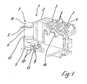
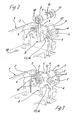
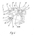
- Figuren 1 bis 4
- das erfindungsgemäße Gehäuse in einem Teilausschnitt, jeweils in einer anderen Funktionsstellung
- Figuren 5 und 6
- Einzelheiten des erfindungsgemäßen Gehäuses jeweils in einer perspektivischen Ansicht
- Figur 7
- die Einzelheit nach Figur 6 in einer Draufsicht
- Figur 8
- die Einzelheit in einer perspektivischen Ansicht
- Figur 9
- einen Schnitt durch die Einzelheit gemäß der Linie IX - IX in Figur 7
- In den Figuren 1 bis 4 ist das Unterteil 2 eines zweiteiligen Gehäuses 1 dargestellt, das mehrere Durchführungen 3 aufweist, die nebeneinander liegend in einer Wandung des Unterteiles 2 angeordnet sind und jeweils halbschalenförmig ausgebildet sind. Komplettiert werden die Durchführungen 3 durch das Aufsetzen des nicht dargestellten Oberteiles, das die anderen Hälften der als Halbschalen vorliegenden Durchführungen 3 bilden, so dass sich insgesamt in montierter Stellung des Ober- und Unterteiles 2 Durchführungen 3 für Leiter mit runden Querschnitten ergeben. Ein solcher Leiter ist in der Figur 4 mit dem Bezugszeichen 15 versehen.
- Jede Durchführung 3 weist zwei angespritzte Dichtwülste 4 auf, deren lichte Durchmesser unterschiedlich sind, entsprechend dem Durchmesser eines durchgeführten Leiters, an dem sie dann dichtend anliegen.
- Das Gehäuse 1 weist weiter eine aus einem Kunststoff gebildete Dichtbuchse 6 auf, die, wie die Figuren 2 bis 4 sehr deutlich zeigen, in Funktionsstellung in einer der Durchführungen 3 einliegt und die eine axiale Durchgangsöffnung 17 aufweist mit mehreren umfänglichen Dichtlippen 20 (Figur 9). Die lichten Durchmesser im Durchgangsbereich dieser Dichtlippen 20 sind ebenfalls unterschiedlich groß und entsprechen den Durchmessern von verschiedenen Leitern 15, die von außen in das Gehäuse 1 geführt werden. Im Funktionsfall liegen die Dichtlippen 20 an dem entsprechenden Kabel dichtend an.
- In der Figur 1 ist die Dichtbuchse 6 in einer Nichtgebrauchsstellung gezeigt, in der sie am Unterteil 2 außerhalb der Durchführöffnung 3 fixiert ist. Hierzu ist in die Durchgangsöffnung 17 ein Stopfen 7 eingesteckt, der an einem Ende einen Kopf 11 aufweist, der die Stirnseite der Dichtbuchse 6 überdeckt, und am anderen Ende zwei federnde Rastzungen 10, die in eine Ausnehmung 18 (Figur 2) des Bodens des Unterteiles 2 eingesteckt und dort gehalten sind.
- Der Stopfen 7, dessen Rastzungen 10 aus der Dichtbuchse 6 herausragen, ist über ein Ösenband 8 verliergesichert mit der Dichtbuchse 6 verbunden, wobei das Ösenband 8 eine Öse 9 aufweist, die in einer umlaufenden Ringnut 21 an den Rastzungen 10 arretiert einliegt.
- Der Stopfen 7 weist weiterhin entsprechend der Anzahl der Dichtlippen 20 umlaufende Nuten 16 auf, in denen, wenn der Stopfen 7 in die Dichtbuchse 6 eingesteckt ist, die Dichtlippen 20 geschützt einliegen.
- In der Figur 2 ist eine Position dargestellt, bevor der Stopfen 7 in die Dichtbuchse 6 eingesteckt ist, während in der Figur 3 der Stopfen 7 die Dichtbuchse 6 als Blindstopfen verschließt. In dieser Figur ist auch erkennbar, dass zwischen dem Kopf 11 und der Stirnseite der Dichtbuchse 6 ein Spalt 5 gebildet ist, der einen äußeren Dichtwulst der Durchführung 3 aufnimmt, während eine umlaufende Nut 12 der Dichtbuchse 6 einen inneren Dichtwulst 4 überdeckt.
- Während in den Figuren 2 und 3 die Dichtbuchse 6 durch den Stopfen 7 verschlossen ist, also kein Leiter 15 durchgeführt ist, ist in der Figur 4 der Leiter 15 in die Durchgangsöffnung 17 eingesteckt. Des weiteren ist zu erkennen, dass die Dichtbuchse 6 Aussparungen 13 aufweist (Figur 6), in die Stege 14 der Wandung des Unterteiles 2 eingreifen, so dass eine exakte Arretierung der Dichtbuchse 6 gewährleistet ist.
- Der Stopfen 7 ist bei Nichtgebrauch entsprechend der Darstellung in Figur 4 über das Ösenband 8 verliergesichert mit der Dichtbuchse 6 verbunden und in der Ausnehmung 18 des Unterteiles 2 arretiert.
- Zur einfachen Durchführung eines Leiters mit angeschlossenem Leiter ist die Dichtbuchse 6 mit einem Längsschlitz 19 versehen, der von außen bis zur Durchgangsöffnung 17 und über die gesamte Länge der Dichtbuchse 6 geführt ist, so dass je nach Durchmesser des eingeführten Leiters 15 sich die gebildeten Schenkel der Dichtbuchse 6 mehr oder weniger weit aufspreizten und die zugeordnete Dichtlippe an dem Leiter 15 dichtend zur Anlage kommt. Durch Verspannen des Oberteiles mit dem Unterteil 2 wird die üblicherweise aus Kunststoff bestehende Dichthülse 6 so zusammengepresst, dass die entsprechende Dichtlippe 20 dicht an dem Leiter 15 anliegt.
-
- 1
- Gehäuse
- 2
- Unterteil
- 3
- Durchführung
- 4
- Dichtwulst
- 5
- Spalt
- 6
- Dichtbuchse
- 7
- Stopfen
- 8
- Ösenband
- 9
- Öse
- 10
- Rastzunge
- 11
- Kopf
- 12
- Nut
- 13
- Aussparung
- 14
- Steg
- 15
- Leiter
- 16
- Nut
- 17
- Durchgangsöffnung
- 18
- Ausnehmung
- 19
- Längsschlitz
- 20
- Dichtlippe
- 21
- Ringnut
Claims (16)
- Ein Ober- und ein Unterteil (2) aufweisendes Gehäuse (1) mit einer Durchführung (3) für einen elektrischen Leiter (15), wobei die Durchführung mindestens einen Dichtwulst (4) aufweist, dadurch gekennzeichnet, dass eine Dichtbuchse (6) vorgesehen ist, die in die Durchführung (3) einlegbar ist und die eine axiale Durchgangsöffnung (17) mit mindestens einer umfänglichen Dichtlippe (20) aufweist.
- Gehäuse nach Anspruch 1, dadurch gekennzeichnet, dass die Dichtbuchse (6) mehrere Dichtlippen (20) mit jeweils einem anderen lichten Durchmesser aufweist.
- Gehäuse nach Anspruch 1 oder 2, dadurch gekennzeichnet, dass die Dichtbuchse (6) zumindest eine umfängliche Nut aufweist, die bei in die Durchführöffnung (3) eingesetzter Stellung einen zugeordneten Dichtwulst (4) umgreift.
- Gehäuse nach einem der vorhergehenden Ansprüche, dadurch gekennzeichnet, dass die Dichtbuchse (6) einen Längsschlitz (19) aufweist, der sich über die gesamte Länge und von außen bis in die Durchgangsöffnung (17) erstreckt.
- Gehäuse nach einem der vorhergehenden Ansprüche, dadurch gekennzeichnet, dass die Dichtbuchse (6) mit Aussparungen (13) versehen ist, in denen Stege (14) des Gehäuses (1) einliegen.
- Gehäuse nach einem der vorhergehenden Ansprüche, dadurch gekennzeichnet, dass ein Stopfen (7) vorgesehen ist, der bei Nichtgebrauch der Dichtbuchse (6) in diese eingesteckt ist.
- Gehäuse nach einem der vorhergehenden Ansprüche, dadurch gekennzeichnet, dass der Stopfen (7) umfängliche Nuten (16) aufweist, in denen bei in die Dichtbuchse (6) eingesteckter Stellung die Dichtlippen (20) einliegen.
- Gehäuse nach einem der vorhergehenden Ansprüche, dadurch gekennzeichnet, dass der Stopfen (7) an einem Ende einen Kopf (11) aufweist, der die zugeordnete Stirnseite der Dichtbuchse (6) überdeckt.
- Gehäuse nach einem der vorhergehenden Ansprüche, dadurch gekennzeichnet, dass der Stopfen (7) an seinem dem Kopf (11) gegenüberliegenden Endbereich federnde Rastzungen aufweist, die in eine Ausnehmung (18) des Gehäuses (1) form- und/oder reibschlüssig einsteckbar sind.
- Gehäuse nach einem der vorhergehenden Ansprüche, dadurch gekennzeichnet, dass der Stopfen (7) verliergesichert mit der Dichtbuchse (6) verbunden ist.
- Gehäuse nach einem der vorhergehenden Ansprüche, dadurch gekennzeichnet, dass zur Verliersicherung des Stopfens (7) ein Ösenband (8) vorgesehen ist, das einerseits mit der Dichtbuchse (6) und andererseits mit dem Stopfen (7) verbunden ist.
- Gehäuse nach einem der vorhergehenden Ansprüche, dadurch gekennzeichnet, dass das Ösenband (8) an einem Ende eine Öse (9) aufweist, die formschlüssig mit dem Stopfen (7) verbunden ist.
- Gehäuse nach einem der vorhergehenden Ansprüche, dadurch gekennzeichnet, dass die Öse (9) im Bereich der federnden Rastzungen (10) lösbar an dem Stopfen (7) angeschlossen ist.
- Gehäuse nach einem der vorhergehenden Ansprüche, dadurch gekennzeichnet, dass die Dichtbuchse (6) aus einem elastischen Material, vorzugsweise einem Kunststoff besteht.
- Gehäuse nach einem der vorhergehenden Ansprüche, dadurch gekennzeichnet, dass die Dichtlippen (20) elastisch verformbar sind.
- Gehäuse nach einem der vorhergehenden Ansprüche, dadurch gekennzeichnet, dass die Dichtbuchse (6) durch Verspannen des Oberteiles mit dem Unterteil (2) derart verformbar ist, dass die jeweils zugeordnete Dichtlippe (20) an dem entsprechenden eingeführten Leiter (15) dichtend anliegt.
Applications Claiming Priority (1)
| Application Number | Priority Date | Filing Date | Title |
|---|---|---|---|
| DE202005006965U DE202005006965U1 (de) | 2005-04-30 | 2005-04-30 | Gehäuse mit einer Durchführung für einen elektrischen Leiter |
Publications (3)
| Publication Number | Publication Date |
|---|---|
| EP1717922A2 true EP1717922A2 (de) | 2006-11-02 |
| EP1717922A3 EP1717922A3 (de) | 2011-05-04 |
| EP1717922B1 EP1717922B1 (de) | 2012-06-06 |
Family
ID=36654756
Family Applications (1)
| Application Number | Title | Priority Date | Filing Date |
|---|---|---|---|
| EP06111512A Expired - Lifetime EP1717922B1 (de) | 2005-04-30 | 2006-03-21 | Gehäuse mit einer Durchführung für einen elektrischen Leiter |
Country Status (4)
| Country | Link |
|---|---|
| US (1) | US7408110B2 (de) |
| EP (1) | EP1717922B1 (de) |
| JP (1) | JP2006310315A (de) |
| DE (1) | DE202005006965U1 (de) |
Cited By (2)
| Publication number | Priority date | Publication date | Assignee | Title |
|---|---|---|---|---|
| EP3021013A4 (de) * | 2013-07-10 | 2016-06-15 | Zte Corp | Dichtungsstruktur |
| CN114928005A (zh) * | 2022-05-27 | 2022-08-19 | 中国重汽集团济南动力有限公司 | 一种低噪音重卡电器接线盒 |
Families Citing this family (2)
| Publication number | Priority date | Publication date | Assignee | Title |
|---|---|---|---|---|
| JP2009043600A (ja) * | 2007-08-09 | 2009-02-26 | Yazaki Corp | 防水コネクタ用ゴム栓体、および防水コネクタ |
| CN113224709B (zh) * | 2020-11-22 | 2022-04-12 | 胜利油田恒源电气有限责任公司 | 一种耐腐蚀的电力金具 |
Citations (1)
| Publication number | Priority date | Publication date | Assignee | Title |
|---|---|---|---|---|
| DE10125625A1 (de) | 2001-05-25 | 2002-12-12 | Langmatz Lic Gmbh | Dichtungstülle insbesondere für einen Kabelübergangskasten |
Family Cites Families (16)
| Publication number | Priority date | Publication date | Assignee | Title |
|---|---|---|---|---|
| DE3201324A1 (de) * | 1982-01-18 | 1983-07-28 | Elektro-Bals Inh. Elisabeth Bals, 5942 Kirchhundem | Kabeleinfuehrungstuelle |
| AT394477B (de) * | 1990-01-03 | 1992-04-10 | Vaillant Gmbh | Kabeldurchfuehrung |
| JPH07130239A (ja) * | 1993-11-01 | 1995-05-19 | Sony Corp | コードブッシュ |
| US5397859A (en) * | 1993-12-10 | 1995-03-14 | The Whitaker Corporation | Enclosure with sealant for spliced coaxial cables |
| DE59402663D1 (de) * | 1993-12-22 | 1997-06-12 | Rxs Schrumpftech Garnituren | Kabelmuffe aus einem längsgeteilten Gehäuse |
| FR2723162B1 (fr) * | 1994-07-29 | 1996-10-04 | Connecteurs Albert Bonneau Cab | Joint annulaire d'etancheite |
| JPH0917646A (ja) * | 1995-06-28 | 1997-01-17 | Tokin Corp | ブッシュ、ブッシュ型磁心及びそれを用いたノイズフィルタ |
| DE19701511C2 (de) * | 1996-01-18 | 2000-10-26 | Draexlmaier Lisa Gmbh | Tülle zur Durchführung von elektrischen Leitungen durch Wandungen, insbesondere in Kraftfahrzeugen |
| JPH1198650A (ja) * | 1997-09-19 | 1999-04-09 | Oki Electric Ind Co Ltd | 円柱状ブッシュ |
| JPH11260176A (ja) * | 1998-03-12 | 1999-09-24 | Yazaki Corp | 導電防水グロメット |
| US6064003A (en) * | 1998-04-16 | 2000-05-16 | Lear Automotive Dearborn, Inc | Grommet and connector seal for use with flat flexible cable |
| US6396990B1 (en) * | 1998-06-12 | 2002-05-28 | Netrix Technologies, Inc. | Multi-purpose communications cabinet |
| DE19907204A1 (de) * | 1999-02-19 | 2000-08-24 | Delphi Tech Inc | Dichtelement |
| DE10323080A1 (de) * | 2003-05-22 | 2004-12-09 | Abb Patent Gmbh | Stopfen zum Verschließen einer in einem Gehäuse vorgesehenen Öffnung zur Durchführung von Kabeln |
| DE10333499A1 (de) * | 2003-07-22 | 2005-02-10 | Murrplastik Systemtechnik Gmbh | Kabeldurchführungsplatte |
| SE527755C2 (sv) * | 2004-02-25 | 2006-05-30 | Paul Tapper | Kabelgenomföringsanordning för enkel installation |
-
2005
- 2005-04-30 DE DE202005006965U patent/DE202005006965U1/de not_active Expired - Lifetime
-
2006
- 2006-03-21 EP EP06111512A patent/EP1717922B1/de not_active Expired - Lifetime
- 2006-04-21 US US11/409,131 patent/US7408110B2/en not_active Expired - Fee Related
- 2006-04-27 JP JP2006123953A patent/JP2006310315A/ja active Pending
Patent Citations (1)
| Publication number | Priority date | Publication date | Assignee | Title |
|---|---|---|---|---|
| DE10125625A1 (de) | 2001-05-25 | 2002-12-12 | Langmatz Lic Gmbh | Dichtungstülle insbesondere für einen Kabelübergangskasten |
Cited By (3)
| Publication number | Priority date | Publication date | Assignee | Title |
|---|---|---|---|---|
| EP3021013A4 (de) * | 2013-07-10 | 2016-06-15 | Zte Corp | Dichtungsstruktur |
| CN114928005A (zh) * | 2022-05-27 | 2022-08-19 | 中国重汽集团济南动力有限公司 | 一种低噪音重卡电器接线盒 |
| CN114928005B (zh) * | 2022-05-27 | 2024-02-20 | 中国重汽集团济南动力有限公司 | 一种低噪音重卡电器接线盒 |
Also Published As
| Publication number | Publication date |
|---|---|
| US7408110B2 (en) | 2008-08-05 |
| DE202005006965U1 (de) | 2006-09-07 |
| US20060243474A1 (en) | 2006-11-02 |
| JP2006310315A (ja) | 2006-11-09 |
| EP1717922A3 (de) | 2011-05-04 |
| EP1717922B1 (de) | 2012-06-06 |
Similar Documents
| Publication | Publication Date | Title |
|---|---|---|
| DE69208627T2 (de) | Wasserdichte Verbinder | |
| DE102006016882B4 (de) | Steckverbinder | |
| EP1524731B1 (de) | Steckergehäuse mit verbesserter Kabelabdichtung | |
| WO2015185511A2 (de) | Elektrisches gerät | |
| EP2249448A2 (de) | Kabeldurchführung | |
| EP2896093B1 (de) | Elektrischer kontaktstecker sowie steckergehäuse | |
| DE102017101870A1 (de) | Steckverbindergehäuse | |
| DE112019001475T5 (de) | Fluidvorrichtung | |
| DE69310692T2 (de) | Rastverbindungen für Aggregate sowie Befestigungselemente dafür | |
| EP2614565A2 (de) | Kabeldurchführung | |
| EP3413414B1 (de) | Dichtungsmuffe für einen rohrverband | |
| EP1717922B1 (de) | Gehäuse mit einer Durchführung für einen elektrischen Leiter | |
| DE68907211T2 (de) | Markierungsanordnung. | |
| DE1615823B2 (de) | Elektrische Steckvorrichtung mit einem Steck- und einem Dosenteil | |
| DE102016217456B3 (de) | Anordnung für einen elektrischen Steckverbinder sowie Steckverbinder mit einem Kontaktgehäuse, Umgehäuse und Sicherungselement | |
| DE202017006800U1 (de) | Innenliegende Zugentlastung für einen Steckverbinder | |
| EP3503307B1 (de) | Elektrisches kupplungsteil | |
| EP2911311B1 (de) | Vorrichtung zum Absorbieren bzw. Reduzieren von Störsignalen auf einem elektrischen Leiter | |
| DE10125625C2 (de) | Dichtungstülle insbesondere für einen Kabelübergangskasten | |
| DE102013016765A1 (de) | Montageelement zur Positionierung einer Betriebsmittelleitung | |
| DE19907204A1 (de) | Dichtelement | |
| DE9311448U1 (de) | Lampenfassung für eine Niederspannungslampe mit zwei Steckerstiften | |
| EP1978289A1 (de) | Vorrichtung zum Durchführen einer Leitung | |
| DE102015220685A1 (de) | Zugentlastungselement für eine Leitung, Aufnahmeeinrichtung, Zugentlastungsvorrichtung und Gehäuse | |
| DE3120524C2 (de) |
Legal Events
| Date | Code | Title | Description |
|---|---|---|---|
| PUAI | Public reference made under article 153(3) epc to a published international application that has entered the european phase |
Free format text: ORIGINAL CODE: 0009012 |
|
| AK | Designated contracting states |
Kind code of ref document: A2 Designated state(s): AT BE BG CH CY CZ DE DK EE ES FI FR GB GR HU IE IS IT LI LT LU LV MC NL PL PT RO SE SI SK TR |
|
| AX | Request for extension of the european patent |
Extension state: AL BA HR MK YU |
|
| PUAL | Search report despatched |
Free format text: ORIGINAL CODE: 0009013 |
|
| AK | Designated contracting states |
Kind code of ref document: A3 Designated state(s): AT BE BG CH CY CZ DE DK EE ES FI FR GB GR HU IE IS IT LI LT LU LV MC NL PL PT RO SE SI SK TR |
|
| AX | Request for extension of the european patent |
Extension state: AL BA HR MK YU |
|
| 17P | Request for examination filed |
Effective date: 20110415 |
|
| RIC1 | Information provided on ipc code assigned before grant |
Ipc: H02G 3/08 20060101AFI20110615BHEP |
|
| 17Q | First examination report despatched |
Effective date: 20110624 |
|
| AKX | Designation fees paid |
Designated state(s): AT BE BG CH CY CZ DE DK EE ES FI FR GB GR HU IE IS IT LI LT LU LV MC NL PL PT RO SE SI SK TR |
|
| GRAP | Despatch of communication of intention to grant a patent |
Free format text: ORIGINAL CODE: EPIDOSNIGR1 |
|
| GRAS | Grant fee paid |
Free format text: ORIGINAL CODE: EPIDOSNIGR3 |
|
| GRAA | (expected) grant |
Free format text: ORIGINAL CODE: 0009210 |
|
| AK | Designated contracting states |
Kind code of ref document: B1 Designated state(s): AT BE BG CH CY CZ DE DK EE ES FI FR GB GR HU IE IS IT LI LT LU LV MC NL PL PT RO SE SI SK TR |
|
| REG | Reference to a national code |
Ref country code: GB Ref legal event code: FG4D Free format text: NOT ENGLISH |
|
| REG | Reference to a national code |
Ref country code: CH Ref legal event code: EP Ref country code: AT Ref legal event code: REF Ref document number: 561423 Country of ref document: AT Kind code of ref document: T Effective date: 20120615 |
|
| REG | Reference to a national code |
Ref country code: IE Ref legal event code: FG4D Free format text: LANGUAGE OF EP DOCUMENT: GERMAN |
|
| REG | Reference to a national code |
Ref country code: DE Ref legal event code: R096 Ref document number: 502006011530 Country of ref document: DE Effective date: 20120809 |
|
| REG | Reference to a national code |
Ref country code: NL Ref legal event code: VDEP Effective date: 20120606 |
|
| PG25 | Lapsed in a contracting state [announced via postgrant information from national office to epo] |
Ref country code: LT Free format text: LAPSE BECAUSE OF FAILURE TO SUBMIT A TRANSLATION OF THE DESCRIPTION OR TO PAY THE FEE WITHIN THE PRESCRIBED TIME-LIMIT Effective date: 20120606 Ref country code: CY Free format text: LAPSE BECAUSE OF FAILURE TO SUBMIT A TRANSLATION OF THE DESCRIPTION OR TO PAY THE FEE WITHIN THE PRESCRIBED TIME-LIMIT Effective date: 20120606 Ref country code: FI Free format text: LAPSE BECAUSE OF FAILURE TO SUBMIT A TRANSLATION OF THE DESCRIPTION OR TO PAY THE FEE WITHIN THE PRESCRIBED TIME-LIMIT Effective date: 20120606 Ref country code: SE Free format text: LAPSE BECAUSE OF FAILURE TO SUBMIT A TRANSLATION OF THE DESCRIPTION OR TO PAY THE FEE WITHIN THE PRESCRIBED TIME-LIMIT Effective date: 20120606 |
|
| REG | Reference to a national code |
Ref country code: LT Ref legal event code: MG4D Effective date: 20120606 |
|
| PG25 | Lapsed in a contracting state [announced via postgrant information from national office to epo] |
Ref country code: GR Free format text: LAPSE BECAUSE OF FAILURE TO SUBMIT A TRANSLATION OF THE DESCRIPTION OR TO PAY THE FEE WITHIN THE PRESCRIBED TIME-LIMIT Effective date: 20120907 Ref country code: LV Free format text: LAPSE BECAUSE OF FAILURE TO SUBMIT A TRANSLATION OF THE DESCRIPTION OR TO PAY THE FEE WITHIN THE PRESCRIBED TIME-LIMIT Effective date: 20120606 Ref country code: SI Free format text: LAPSE BECAUSE OF FAILURE TO SUBMIT A TRANSLATION OF THE DESCRIPTION OR TO PAY THE FEE WITHIN THE PRESCRIBED TIME-LIMIT Effective date: 20120606 |
|
| PG25 | Lapsed in a contracting state [announced via postgrant information from national office to epo] |
Ref country code: EE Free format text: LAPSE BECAUSE OF FAILURE TO SUBMIT A TRANSLATION OF THE DESCRIPTION OR TO PAY THE FEE WITHIN THE PRESCRIBED TIME-LIMIT Effective date: 20120606 Ref country code: NL Free format text: LAPSE BECAUSE OF FAILURE TO SUBMIT A TRANSLATION OF THE DESCRIPTION OR TO PAY THE FEE WITHIN THE PRESCRIBED TIME-LIMIT Effective date: 20120606 Ref country code: IS Free format text: LAPSE BECAUSE OF FAILURE TO SUBMIT A TRANSLATION OF THE DESCRIPTION OR TO PAY THE FEE WITHIN THE PRESCRIBED TIME-LIMIT Effective date: 20121006 Ref country code: RO Free format text: LAPSE BECAUSE OF FAILURE TO SUBMIT A TRANSLATION OF THE DESCRIPTION OR TO PAY THE FEE WITHIN THE PRESCRIBED TIME-LIMIT Effective date: 20120606 Ref country code: CZ Free format text: LAPSE BECAUSE OF FAILURE TO SUBMIT A TRANSLATION OF THE DESCRIPTION OR TO PAY THE FEE WITHIN THE PRESCRIBED TIME-LIMIT Effective date: 20120606 Ref country code: SK Free format text: LAPSE BECAUSE OF FAILURE TO SUBMIT A TRANSLATION OF THE DESCRIPTION OR TO PAY THE FEE WITHIN THE PRESCRIBED TIME-LIMIT Effective date: 20120606 |
|
| PG25 | Lapsed in a contracting state [announced via postgrant information from national office to epo] |
Ref country code: PL Free format text: LAPSE BECAUSE OF FAILURE TO SUBMIT A TRANSLATION OF THE DESCRIPTION OR TO PAY THE FEE WITHIN THE PRESCRIBED TIME-LIMIT Effective date: 20120606 Ref country code: IT Free format text: LAPSE BECAUSE OF FAILURE TO SUBMIT A TRANSLATION OF THE DESCRIPTION OR TO PAY THE FEE WITHIN THE PRESCRIBED TIME-LIMIT Effective date: 20120606 Ref country code: PT Free format text: LAPSE BECAUSE OF FAILURE TO SUBMIT A TRANSLATION OF THE DESCRIPTION OR TO PAY THE FEE WITHIN THE PRESCRIBED TIME-LIMIT Effective date: 20121008 |
|
| PLBE | No opposition filed within time limit |
Free format text: ORIGINAL CODE: 0009261 |
|
| STAA | Information on the status of an ep patent application or granted ep patent |
Free format text: STATUS: NO OPPOSITION FILED WITHIN TIME LIMIT |
|
| PG25 | Lapsed in a contracting state [announced via postgrant information from national office to epo] |
Ref country code: DK Free format text: LAPSE BECAUSE OF FAILURE TO SUBMIT A TRANSLATION OF THE DESCRIPTION OR TO PAY THE FEE WITHIN THE PRESCRIBED TIME-LIMIT Effective date: 20120606 Ref country code: ES Free format text: LAPSE BECAUSE OF FAILURE TO SUBMIT A TRANSLATION OF THE DESCRIPTION OR TO PAY THE FEE WITHIN THE PRESCRIBED TIME-LIMIT Effective date: 20120917 |
|
| 26N | No opposition filed |
Effective date: 20130307 |
|
| REG | Reference to a national code |
Ref country code: DE Ref legal event code: R097 Ref document number: 502006011530 Country of ref document: DE Effective date: 20130307 |
|
| PG25 | Lapsed in a contracting state [announced via postgrant information from national office to epo] |
Ref country code: BG Free format text: LAPSE BECAUSE OF FAILURE TO SUBMIT A TRANSLATION OF THE DESCRIPTION OR TO PAY THE FEE WITHIN THE PRESCRIBED TIME-LIMIT Effective date: 20120906 |
|
| BERE | Be: lapsed |
Owner name: WEIDMULLER INTERFACE G.M.B.H. & CO. KG Effective date: 20130331 |
|
| PG25 | Lapsed in a contracting state [announced via postgrant information from national office to epo] |
Ref country code: MC Free format text: LAPSE BECAUSE OF NON-PAYMENT OF DUE FEES Effective date: 20130331 |
|
| REG | Reference to a national code |
Ref country code: CH Ref legal event code: PL |
|
| GBPC | Gb: european patent ceased through non-payment of renewal fee |
Effective date: 20130321 |
|
| REG | Reference to a national code |
Ref country code: FR Ref legal event code: ST Effective date: 20131129 |
|
| REG | Reference to a national code |
Ref country code: IE Ref legal event code: MM4A |
|
| REG | Reference to a national code |
Ref country code: DE Ref legal event code: R119 Ref document number: 502006011530 Country of ref document: DE Effective date: 20131001 |
|
| PG25 | Lapsed in a contracting state [announced via postgrant information from national office to epo] |
Ref country code: BE Free format text: LAPSE BECAUSE OF NON-PAYMENT OF DUE FEES Effective date: 20130331 Ref country code: CH Free format text: LAPSE BECAUSE OF NON-PAYMENT OF DUE FEES Effective date: 20130331 Ref country code: LI Free format text: LAPSE BECAUSE OF NON-PAYMENT OF DUE FEES Effective date: 20130331 Ref country code: IE Free format text: LAPSE BECAUSE OF NON-PAYMENT OF DUE FEES Effective date: 20130321 Ref country code: GB Free format text: LAPSE BECAUSE OF NON-PAYMENT OF DUE FEES Effective date: 20130321 Ref country code: FR Free format text: LAPSE BECAUSE OF NON-PAYMENT OF DUE FEES Effective date: 20130402 Ref country code: DE Free format text: LAPSE BECAUSE OF NON-PAYMENT OF DUE FEES Effective date: 20131001 |
|
| REG | Reference to a national code |
Ref country code: AT Ref legal event code: MM01 Ref document number: 561423 Country of ref document: AT Kind code of ref document: T Effective date: 20130321 |
|
| PG25 | Lapsed in a contracting state [announced via postgrant information from national office to epo] |
Ref country code: AT Free format text: LAPSE BECAUSE OF NON-PAYMENT OF DUE FEES Effective date: 20130321 |
|
| PG25 | Lapsed in a contracting state [announced via postgrant information from national office to epo] |
Ref country code: TR Free format text: LAPSE BECAUSE OF FAILURE TO SUBMIT A TRANSLATION OF THE DESCRIPTION OR TO PAY THE FEE WITHIN THE PRESCRIBED TIME-LIMIT Effective date: 20120606 |
|
| PG25 | Lapsed in a contracting state [announced via postgrant information from national office to epo] |
Ref country code: HU Free format text: LAPSE BECAUSE OF FAILURE TO SUBMIT A TRANSLATION OF THE DESCRIPTION OR TO PAY THE FEE WITHIN THE PRESCRIBED TIME-LIMIT; INVALID AB INITIO Effective date: 20060321 Ref country code: LU Free format text: LAPSE BECAUSE OF NON-PAYMENT OF DUE FEES Effective date: 20130321 |