EP1524731B1 - Steckergehäuse mit verbesserter Kabelabdichtung - Google Patents
Steckergehäuse mit verbesserter Kabelabdichtung Download PDFInfo
- Publication number
- EP1524731B1 EP1524731B1 EP04023892A EP04023892A EP1524731B1 EP 1524731 B1 EP1524731 B1 EP 1524731B1 EP 04023892 A EP04023892 A EP 04023892A EP 04023892 A EP04023892 A EP 04023892A EP 1524731 B1 EP1524731 B1 EP 1524731B1
- Authority
- EP
- European Patent Office
- Prior art keywords
- plug housing
- cable
- housing according
- sealing insert
- slot
- Prior art date
- Legal status (The legal status is an assumption and is not a legal conclusion. Google has not performed a legal analysis and makes no representation as to the accuracy of the status listed.)
- Expired - Lifetime
Links
- 238000007789 sealing Methods 0.000 title claims abstract description 54
- 239000000463 material Substances 0.000 claims description 6
- 230000000717 retained effect Effects 0.000 abstract 1
- 230000007704 transition Effects 0.000 description 4
- 239000002184 metal Substances 0.000 description 3
- 230000002093 peripheral effect Effects 0.000 description 2
- 230000001419 dependent effect Effects 0.000 description 1
- 210000004907 gland Anatomy 0.000 description 1
- 239000012212 insulator Substances 0.000 description 1
- 230000036316 preload Effects 0.000 description 1
Images


Classifications
-
- H—ELECTRICITY
- H01—ELECTRIC ELEMENTS
- H01R—ELECTRICALLY-CONDUCTIVE CONNECTIONS; STRUCTURAL ASSOCIATIONS OF A PLURALITY OF MUTUALLY-INSULATED ELECTRICAL CONNECTING ELEMENTS; COUPLING DEVICES; CURRENT COLLECTORS
- H01R13/00—Details of coupling devices of the kinds covered by groups H01R12/70 or H01R24/00 - H01R33/00
- H01R13/46—Bases; Cases
- H01R13/52—Dustproof, splashproof, drip-proof, waterproof, or flameproof cases
- H01R13/5205—Sealing means between cable and housing, e.g. grommet
-
- H—ELECTRICITY
- H01—ELECTRIC ELEMENTS
- H01R—ELECTRICALLY-CONDUCTIVE CONNECTIONS; STRUCTURAL ASSOCIATIONS OF A PLURALITY OF MUTUALLY-INSULATED ELECTRICAL CONNECTING ELEMENTS; COUPLING DEVICES; CURRENT COLLECTORS
- H01R13/00—Details of coupling devices of the kinds covered by groups H01R12/70 or H01R24/00 - H01R33/00
- H01R13/46—Bases; Cases
- H01R13/52—Dustproof, splashproof, drip-proof, waterproof, or flameproof cases
- H01R13/5202—Sealing means between parts of housing or between housing part and a wall, e.g. sealing rings
-
- H—ELECTRICITY
- H01—ELECTRIC ELEMENTS
- H01R—ELECTRICALLY-CONDUCTIVE CONNECTIONS; STRUCTURAL ASSOCIATIONS OF A PLURALITY OF MUTUALLY-INSULATED ELECTRICAL CONNECTING ELEMENTS; COUPLING DEVICES; CURRENT COLLECTORS
- H01R13/00—Details of coupling devices of the kinds covered by groups H01R12/70 or H01R24/00 - H01R33/00
- H01R13/46—Bases; Cases
- H01R13/502—Bases; Cases composed of different pieces
- H01R13/512—Bases; Cases composed of different pieces assembled by screw or screws
-
- Y—GENERAL TAGGING OF NEW TECHNOLOGICAL DEVELOPMENTS; GENERAL TAGGING OF CROSS-SECTIONAL TECHNOLOGIES SPANNING OVER SEVERAL SECTIONS OF THE IPC; TECHNICAL SUBJECTS COVERED BY FORMER USPC CROSS-REFERENCE ART COLLECTIONS [XRACs] AND DIGESTS
- Y10—TECHNICAL SUBJECTS COVERED BY FORMER USPC
- Y10S—TECHNICAL SUBJECTS COVERED BY FORMER USPC CROSS-REFERENCE ART COLLECTIONS [XRACs] AND DIGESTS
- Y10S439/00—Electrical connectors
- Y10S439/901—Connector hood or shell
- Y10S439/904—Multipart shell
- Y10S439/906—Longitudinally divided
Definitions
- the invention relates to a connector housing, which is particularly suitable for receiving a pre-assembled cable.
- a prefabricated cable is characterized in that its wires are already connected to contacts, which in turn may already be arranged in an insulating body.
- the pre-assembled cables are used, for example, to make the wiring of electrical equipment on site, the cables must be guided depending on the spatial conditions in different directions to the devices.
- the insulating body is inserted with the contacts in a plug housing, which is adapted to the spatial conditions on site, for example, in terms of cable outlet direction.
- the problem with prefabricated cables is that due to the already attached contacts and the insulating body, the cable can not be inserted in the axial direction by a cable gland or cable seal in an example closed housing.
- the parting line is arranged so that in the open state, the cable can be placed between the two housing parts. Similar problems arise with respect to the sealing of the cable in the region of the cable passage through the housing. It can not use a closed seal be, because this can not be pushed over the insulating body. Instead, an either slotted or multi-part sealing ring must be used.
- a plug housing with a first housing part, a second housing part and a sealing insert is known from document GB 2 377 821.
- the object of the invention is therefore to provide a connector housing that can be equipped with a pre-assembled cable and can meet high demands on the tightness with little effort.
- a plug housing is provided with a first housing part and a second housing part which abut each other along a parting line, a cable passage for a cable from the inside of the plug housing to the outside, wherein the parting line extends in the region of the cable passage, and a sealing insert, which is arranged in the cable passage, wherein the sealing insert is provided with a slot so that it can be plugged onto a prefabricated cable, and wherein the sealing insert is arranged so that its slot is offset from the parting line.
- This design ensures that the sealing insert can be used with a cable arranged therein in one of the two housing parts, where it remains fixed by friction. Subsequently, the second housing part can be placed and screwed, whereby the sealing insert is compressed so that it seals well.
- a connector which consists of a connector housing 5, in which a plurality of plug contacts are received, which are covered here by a surrounding insulating 7.
- a cable 8 whose wires are connected to the plug contacts in the insulating body 7 leads.
- the cable 8 is guided through a cable passage 9, in the area of which a later-explained sealing takes place.
- the plug housing for this purpose consists of a first housing part 10 and a housing part 12, which along a circumferential parting line 14 (see also Figure 7) can abut each other.
- the parting line 14 is slightly offset relative to a center plane M of the housing to one side. This Offset V is less than 10% of the total maximum width of the connector housing.
- the cable passage 9 is divided by the parting line 14 into two parts, of which the larger part is in the first housing part 10 and the smaller part in the second housing part 12.
- the part of the cable passage 9 located in the first housing part 10 is U-shaped with a base 16 and two side walls 18.
- a projecting web 20 is formed, which is provided on its side facing the parting line 14 with a parallel to this end wall 22 and on its bottom 16 side facing in the region of the transition of the side walls 18 to the bottom 16 expires.
- the first housing part 10 is provided with a peripheral seal 24, which runs along the parting line 14 and also extends through the portion of the cable passage 9 located in the first housing part 10.
- the exposed surface of the seal 24 in this case runs in accordance with the contour of the cable passage 9, thus protruding inwards on the webs 20.
- the seal 24 is provided on each side of the cable passage 9 with two biasing lugs 26 which project beyond the parting line and are chamfered on their side facing away from the cable passage 9 side.
- an abutment 30 is formed.
- the remaining part of the cable passage 9 is formed in the second housing part 12.
- a U-shaped recess is provided which has a bottom and two side walls.
- webs 20 are provided in the side walls, such as in the housing part 10.
- an obliquely extending, correspondingly recessed pressure surface 32 is provided for receiving the preload projections 26.
- a sealing insert 34 is provided, which consists of rubber.
- the material of the sealing insert 34 has a higher hardness than the rubber material of the seal 24.
- the sealing insert 34 is composed of a sealing portion 36, a clamping portion 38 and an intermediate flange 40.
- the sealing portion 36 is provided in the region of the actual cable passage 9 between the two U-shaped depressions in the two housing parts 10, 12 to be arranged. He has, as well as the cable passage 9, an approximately square cross-section with rounded corners.
- the sealing portion 38 is intended to be disposed in the cable clamp 28. He has a round cross section.
- the flange 40 is intended to be received in a Flanschability 42 in the first and in the second housing part 10, 12. It also has a square section with rounded corners.
- the sealing insert 34 is provided with a slot 44 which is arranged in the middle of one of the sides of the square sealing portion 36.
- the slot 44 allows the sealing insert 33 can be placed on the pre-assembled cable 8.
- two grooves 46 are provided which each begin in the region of a rounded corner and terminate at a sufficient distance in front of the slot 44. In the region of the slot 44 thus the wall thickness of the sealing portion 36 remains in the usual strength.
- the grooves 46 are also disposed on the non-visible in Figure 5, the lower side of the sealing portion 36, so that the sealing insert 34 is symmetrical to two mutually perpendicular planes. The first of these planes passes through the slot 44, and the intersection of the two planes coincides with the central axis of the sealing insert 34 and thus also with the central axis of the cable 8.
- the sealing insert 34 is first placed on the cable 8 by the slot 44 is bent so far that the sealing insert 34 can be pushed onto the cable 8. Then, the insulating body 7 in an associated Isolier Sciencesfact 48 disposed in the first housing part 10, and the cable 9 is inserted into the located in the first housing part 10 part of the cable passage 9. In this case, the sealing insert 34 is positioned between the side walls 18, that the two webs 20 engage in opposing grooves 46 of the sealing portion 36 of the sealing insert 34.
- the slot 44 is in this case, since the parting line 14 is offset relative to the center plane M of the housing and thus also the center of the cable passage 9, in the region of one of the side walls 18 (see Figure 7).
- the sealing insert 34 is prefixed correctly and with closed slot 44 in the first housing part 10 despite the slight pressure exerted by the inserted cable 8 and which seeks to spread the slot 44.
- the cable clamp 28 can be completed by a metal clip 50 is screwed onto the abutment 30, which presses on the clamping portion 38 of the sealing insert 34. In this way, the cable can be fixed in the housing part 10. If desired, with the cable clamp 28 consisting of the abutment 30 and the metal clip 50 also a braided shield can be contacted, if the cable 8 is a shielded cable.
- the sealing insert 34 whose dimensions in the initial state are slightly larger than the dimensions of the cable passage 9, slightly compressed so that it rests with bias on the side walls of the cable passage 9.
- the slot 44 of the sealing insert 34 is compressed, so that there is a good seal.
- the good seal is completed by the peripheral seal 24, which seals on the one hand between the two housing parts and on the other hand, due to the biasing lugs 26 in combination with the pressure surfaces 32, in the region of the transition to the sealing insert 34, in particular on the side of the slot 44, seals.
- both between the cable 8 and the sealing insert 34 and between the two housing parts 10, 12 and finally between the sealing insert 34 and the two housing parts 10, 12 a good seal achieved so that an industrial grade of protection IP65 or higher can be achieved.
- the webs 20 could also be provided on the second housing part 12 in order to apply a defined bias on the slot 44 can.
Landscapes
- Connector Housings Or Holding Contact Members (AREA)
- Cable Accessories (AREA)
Description
- Die Erfindung betrifft ein Steckergehäuse, das besonders zur Aufnahme eines vorkonfektionierten Kabels geeignet ist.
- Ein vorkonfektioniertes Kabel zeichnet sich dadurch aus, daß seine Adern bereits mit Kontakten verbunden sind, die wiederum bereits in einem Isolierkörper angeordnet sein können. Die vorkonfektionierten Kabel werden beispielsweise dazu verwendet, vor Ort die Verkabelung von elektrischen Geräten vorzunehmen, wobei die Kabel je nach den räumlichen Verhältnissen in unterschiedlichen Richtungen zu den Geräten geführt werden müssen. Beim Anschließen des Kabels wird der Isolierkörper mit den Kontakten in ein Steckergehäuse eingelegt, das den räumlichen Verhältnissen vor Ort angepaßt ist, beispielsweise hinsichtlich der Kabelabgangsrichtung. Das Problem bei vorkonfektionierten Leitungen besteht darin, daß aufgrund der bereits angebrachten Kontakte und des Isolierkörpers das Kabel nicht in axialer Richtung durch eine Kabelverschraubung bzw. Kabelabdichtung in ein beispielsweise geschlossenes Gehäuse eingeführt werden kann. Es ist statt dessen erforderlich, ein mindestens zweiteiliges Gehäuse zu verwenden, dessen Trennfuge so angeordnet ist, daß im geöffneten Zustand das Kabel zwischen die beiden Gehäuseteile gelegt werden kann. Ähnliche Probleme ergibt sich hinsichtlich der Abdichtung des Kabels im Bereich des Kabeldurchgangs durch das Gehäuse. Es kann kein geschlossener Dichtring verwendet werden, da dieser nicht über den Isolierkörper geschoben werden kann. Statt dessen muß ein entweder geschlitzter oder mehrteiliger Dichtring verwendet werden.
- Ein Steckergehäuse mit einem ersten Gehäuseteil, einem zweiten Gehäuseteil und einem Dichteinsatz ist aus Dokument GB 2 377 821 bekannt.
- Der Nachteil bei mehrteiligen Gehäusen und mehrteiligen bzw. geschlitzten Dichtringen besteht darin, daß eine zuverlässige Abdichtung gegen Schmutzeintritt nur mit besonderem Aufwand möglich ist, insbesondere wenn höhere IP-Schutzklassen erreicht werden sollen.
- Die Aufgabe der Erfindung besteht dementsprechend darin, ein Steckergehäuse zu schaffen, das mit einem vorkonfektionierten Kabel bestückt werden kann und mit geringem Aufwand hohe Anforderungen an die Dichtigkeit einhalten kann.
- Zu diesem Zweck ist erfindungsgemäß ein Steckergehäuse vorgesehen mit einem ersten Gehäuseteil und einem zweiten Gehäuseteil, die entlang einer Trennfuge aneinander anliegen, einem Kabeldurchgang für ein Kabel aus dem Inneren des Steckergehäuses nach außen, wobei die Trennfuge im Bereich des Kabeldurchgangs verläuft, und einem Dichteinsatz, der im Kabeldurchgang angeordnet ist, wobei der Dichteinsatz mit einem Schlitz versehen ist, so daß er auf ein vorkonfektioniertes Kabel aufgesteckt werden kann, und wobei der Dichteinsatz so angeordnet ist, daß sein Schlitz gegenüber der Trennfuge versetzt ist. Diese Gestaltung gewährleistet, daß der Dichteinsatz mit einem darin angeordneten Kabel in eines der beiden Gehäuseteile eingesetzt werden kann, wo er durch Reibung fixiert bleibt. Anschließend kann das zweite Gehäuseteil aufgesetzt und festgeschraubt werden, wodurch der Dichteinsatz so komprimiert wird, daß er gut abdichtet.
- Vorteilhafte Ausgestaltungen der Erfindung ergeben sich aus den Unteransprüchen.
- Die Erfindung wird nachfolgend anhand einer bevorzugten Ausführungsform beschrieben, die in den beigefügten Zeichnungen dargestellt ist. In diesen zeigen:
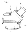
- Figur 1 in einer perspektivischen Ansicht ein erfindungsgemäßes Steckergehäuse mit angebrachtem Kabel;
- Figur 2 das Steckergehäuse von Figur 1 in einer Explosionsansicht;
- Figur 3 in einer Ansicht entsprechend derjenigen von Figur 2 die beiden Gehäuseteile des Steckergehäuses von Figur 1;
- Figur 4 in einer perspektivischen Ansicht ein Detail eines Gehäuseteils;
- Figur 5 in einer perspektivischen, vergrößerten Ansicht einen Dichteinsatz;
- Figur 6 in einer perspektivischen Ansicht das Gehäuseteil von Figur 4 bestückt mit dem Dichteinsatz von Figur 5; und
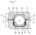
- Figur 7 schematisch einen Schnitt durch das geschlossene Steckergehäuse entlang der Ebene VII-VII von Figur 3.
- In Figur 1 ist ein Steckverbinder gezeigt, der aus einem Steckergehäuse 5 besteht, in welchem mehrere Steckkontakte aufgenommen sind, die hier von einem sie umgebenden Isolierkörper 7 verdeckt sind. In das Steckergehäuse 5 hinein führt ein Kabel 8, dessen Adern mit den Steckkontakten im Isolierkörper 7 verbunden sind. Das Kabel 8 wird durch einen Kabeldurchgang 9 geführt, in dessen Bereich eine später erläuterte Abdichtung erfolgt.
- Beim Kabel 8 handelt es sich um ein vorkonfektioniertes Kabel, dessen Adern bereits fest mit den Steckkontakten im Isolierkörper 7 verbunden sind. Hieraus folgt, daß das Steckergehäuse 5 geöffnet werden muß, da es ansonsten nicht möglich wäre, das Kabel zusammen mit dem Isolierkörper 7 in das Steckergehäuse einzulegen. Wie in Figur 2 zu sehen ist, besteht das Steckergehäuse zu diesem Zweck aus einem ersten Gehäuseteil 10 und einem Gehäuseteil 12, die entlang einer umlaufenden Trennfuge 14 (siehe auch Figur 7) aneinander anliegen können. Wie insbesondere in Figur 7 zu sehen ist, ist die Trennfuge 14 gegenüber einer Mittelebene M des Gehäuses geringfügig zu einer Seite versetzt. Dieser Versatz V beträgt weniger als 10 % der gesamten maximalen Breite des Steckergehäuses.
- Der Kabeldurchgang 9 wird von der Trennfuge 14 in zwei Teile unterteilt, von denen sich der größere Teil im ersten Gehäuseteil 10 und der kleinere Teil im zweiten Gehäuseteil 12 befindet. Der sich im ersten Gehäuseteil 10 befindende Teil des Kabeldurchgangs 9 (siehe insbesondere Figur 4) ist U-förmig mit einem Boden 16 und zwei Seitenwänden 18 ausgeführt. Auf jeder der Seitenwände 18 ist ein vorstehender Steg 20 ausgebildet, der auf seiner der Trennfuge 14 zugewandten Seite mit einer zu dieser parallelen Stirnwand 22 versehen ist und auf seiner dem Boden 16 zugewandten Seite im Bereich des Übergangs der Seitenwände 18 zum Boden 16 ausläuft.
- Das erste Gehäuseteil 10 ist mit einer umlaufenden Dichtung 24 versehen, die entlang der Trennfuge 14 verläuft und auch durch den sich im ersten Gehäuseteil 10 befindenden Teil des Kabeldurchgangs 9 verläuft. Die freiliegende Oberfläche der Dichtung 24 verläuft dabei entsprechend der Kontur des Kabeldurchgangs 9, springt also an den Stegen 20 nach innen vor. Im Bereich des Übergangs jeder Seitenwand zur Trennfuge 14 ist die Dichtung 24 auf jeder Seite des Kabeldurchgangs 9 mit zwei Vorspannansätzen 26 versehen, die über die Trennfuge hinausstehen und auf ihrer vom Kabeldurchgang 9 abgewandten Seite abgeschrägt sind.
- An den Kabeldurchgang 9 schließt sich zum Inneren des Steckergehäuses 5 hin eine Kabelschelle 28 an, von der im ersten Gehäuseteil 10 ein Widerlager 30 ausgebildet ist.
- Der übrige Teil des Kabeldurchgangs 9 ist im zweiten Gehäuseteil 12 ausgebildet. Auch hier ist eine U-förmige Vertiefung vorgesehen, die einen Boden und zwei Seitenwände aufweist. Weiterhin sind in den Seitenwänden, wie im Gehäuseteil 10, Stege 20 vorgesehen. Im Bereich des Übergangs jeder Seitenwand zur Trennfuge ist eine schräg verlaufende, entsprechend vertiefte Druckfläche 32 zur Aufnahme der Vorspannansätze 26 vorgesehen.
- Zur Abdichtung im Bereich des Kabeldurchgangs 9 ist ein Dichteinsatz 34 vorgesehen, der aus Gummi besteht. Das Material des Dichteinsatzes 34 hat eine höhere Härte als das Gummimaterial der Dichtung 24. Der Dichteinsatz 34 setzt sich zusammen aus einem Dichtabschnitt 36, einem Klemmabschnitt 38 und einem dazwischenliegenden Flansch 40. Der Dichtabschnitt 36 ist dafür vorgesehen, im Bereich des eigentlichen Kabeldurchgangs 9 zwischen den beiden U-förmigen Vertiefungen in den beiden Gehäuseteilen 10, 12 angeordnet zu werden. Er hat, ebenso wie der Kabeldurchgang 9, einen etwa quadratischen Querschnitt mit abgerundeten Ecken. Der Dichtabschnitt 38 ist dafür vorgesehen, in der Kabelschelle 28 angeordnet zu werden. Er hat einen runden Querschnitt. Der Flansch 40 ist dafür vorgesehen, in einer Flanschaufnahme 42 im ersten und im zweiten Gehäuseteil 10, 12 aufgenommen zu werden. Er hat ebenfalls einen quadratischen Querschnitt mit abgerundeten Ecken.
- Der Dichteinsatz 34 ist mit einem Schlitz 44 versehen, der in der Mitte einer der Seiten des quadratischen Dichtabschnittes 36 angeordnet ist. Der Schlitz 44 ermöglicht, daß der Dichteinsatz 33 auf das vorkonfektionierte Kabel 8 aufgesetzt werden kann. Auf der Seite des Dichtabschnittes 36, auf der sich der Schlitz 44 befindet, sind zwei Nuten 46 vorgesehen, die jeweils im Bereich einer abgerundeten Ecke beginnen und in einem ausreichenden Abstand vor dem Schlitz 44 enden. Im Bereich des Schlitzes 44 verbleibt also die Wandstärke des Dichtabschnittes 36 in gewohnter Stärke. Die Nuten 46 sind auch auf der in Figur 5 nicht sichtbaren, unteren Seite des Dichtabschnittes 36 angeordnet, so daß der Dichteinsatz 34 zu zwei zueinander senkrechten Ebenen symmetrisch ist. Die erste dieser Ebenen verläuft durch den Schlitz 44, und die Schnittlinie der beiden Ebenen fällt mit der Mittelache des Dichteinsatzes 34 und damit auch mit der Mittelachse des Kabels 8 zusammen.
- Zur Anbringung des vorkonfektionierten Kabels 8 im Steckergehäuse 5 wird zuerst der Dichteinsatz 34 auf das Kabel 8 aufgesetzt, indem der Schlitz 44 so weit aufgebogen wird, daß der Dichteinsatz 34 auf das Kabel 8 aufgeschoben werden kann. Dann wird der Isolierkörper 7 in einer ihm zugeordneten Isolierkörperaufnahme 48 im ersten Gehäuseteil 10 angeordnet, und das Kabel 9 wird in den sich im ersten Gehäuseteil 10 befindenden Teil des Kabeldurchgangs 9 eingelegt. Dabei wird der Dichteinsatz 34 so zwischen den Seitenwänden 18 positioniert, daß die beiden Stege 20 in einander gegenüberliegende Nuten 46 des Dichtabschnittes 36 des Dichteinsatzes 34 eingreifen. Der Schlitz 44 befindet sich dabei, da die Trennfuge 14 gegenüber der Mittelebene M des Gehäuses und damit auch der Mitte des Kabeldurchgangs 9 versetzt ist, im Bereich einer der Seitenwände 18 (siehe Figur 7). Dies gewährleistet, daß der Dichteinsatz 34 trotz des leichten Drucks, den das in ihn eingelegte Kabel 8 ausübt und welcher den Schlitz 44 aufzuspreizen sucht, korrekt und mit geschlossenem Schlitz 44 im ersten Gehäuseteil 10 vorfixiert ist. Anschließend kann die Kabelschelle 28 komplettiert werden, indem auf das Widerlager 30 eine Metallklammer 50 aufgeschraubt wird, die auf den Klemmabschnitt 38 des Dichteinsatzes 34 drückt. Auf diese Weise kann das Kabel im Gehäuseteil 10 fixiert werden. Falls gewünscht, kann mit der aus dem Widerlager 30 und der Metallklammer 50 bestehenden Kabelschelle 28 auch ein Schirmgeflecht kontaktiert werden, wenn es sich beim Kabel 8 um ein abgeschirmtes Kabel handelt.
- Abschließend wird das zweite Gehäuseteil 12 auf das erste Gehäuseteil 10 aufgesetzt und mit diesem verschraubt. Dabei wird der Dichteinsatz 34, dessen Abmessungen im Ausgangszustand geringfügig größer sind als die Abmessungen des Kabeldurchgangs 9, leicht zusammengedrückt, so daß er mit Vorspannung an den Seitenwänden des Kabeldurchgangs 9 anliegt. Durch den aufgebrachten Druck wird auch der Schlitz 44 des Dichteinsatzes 34 zusammengedrückt, so daß sich dort eine gute Abdichtung ergibt. Die gute Abdichtung wird vervollständigt durch die umlaufende Dichtung 24, die zum einen zwischen den beiden Gehäuseteilen abdichtet und zum anderen, aufgrund der Vorspannansätze 26 in Kombination mit den Druckflächen 32, im Bereich des Übergangs zum Dichteinsatz 34, insbesondere auf der Seite des Schlitzes 44, abdichtet. Auf diese Weise ist sowohl zwischen dem Kabel 8 und dem Dichteinsatz 34 als auch zwischen den beiden Gehäuseteilen 10, 12 und schließlich auch zwischen dem Dichteinsatz 34 und den beiden Gehäuseteilen 10, 12 eine gute Abdichtung erzielt, so daß eine industrietaugliche Schutzart von IP65 oder höher erreicht werden kann.
- Gemäß einer nicht dargestellten Weiterbildung der Erfindung könnten die Stege 20 auch am zweiten Gehäuseteil 12 vorgesehen sein, um eine definiertere Vorspannung auf den Schlitz 44 aufbringen zu können.
-
- 5:
- Steckergehäuse
- 7:
- Isolierkörper
- 8:
- Kabel
- 9:
- Kabeldurchgang
- 10:
- erstes Gehäuseteil
- 12:
- zweites Gehäuseteil
- 14:
- Trennfuge
- 16:
- Boden
- 18:
- Seitenwand
- 20:
- Steg
- 22:
- Stirnwand
- 24:
- Dichtung
- 26:
- Vorspannansatz
- 28:
- Kabelschelle
- 30:
- Widerlager
- 32:
- Druckfläche
- 34:
- Dichteinsatz
- 36:
- Dichtabschnitt
- 38:
- Klemmabschnitt
- 40:
- Flansch
- 42:
- Flanschaufnahme
- 44:
- Schlitz
- 46:
- Nut
- 48:
- Isolierkörperaufnahme
- 50:
- Metallklammer
Claims (18)
- Steckergehäuse (5) mit einem ersten Gehäuseteil (10), einem zweiten Gehäuseteil (12), die entlang einer Trennfuge (14) aneinander anliegen, einem Kabeldurchgang (9) für ein Kabel (8) aus dem Innenraum des Steckergehäuses (5) nach außen, wobei die Trennfuge (14) im Bereich des Kabeldurchgangs (9) verläuft, und einem Dichteinsatz (34), der im Kabeldurchgang (9) angeordnet ist, wobei der Dichteinsatz (34) mit einem Schlitz (44) versehen ist, so daß er auf ein vorkonfektioniertes Kabel (8) aufgesteckt werden kann, und wobei der Dichteinsatz (34) so angeordnet ist, daß sein Schlitz (44) gegenüber der Trennfuge (14) versetzt ist.
- Steckergehäuse nach Anspruch 1, dadurch gekennzeichnet, daß die Trennfuge (14) um weniger als 10% der Dicke des Gehäuses (5) gegenüber der Mittelebene (M) des Gehäuses versetzt ist.
- Steckergehäuse nach einem der vorhergehenden Ansprüche, dadurch gekennzeichnet, daß eines der Gehäuseteile (10) mit einer umlaufenden Dichtung (24) versehen ist.
- Steckergehäuse nach Anspruch 3, dadurch gekennzeichnet, daß die Dichtung (24) durch den in diesem Gehäuseteil (10) befindlichen Teil des Kabeldurchgangs (9) verläuft.
- Steckergehäuse nach Anspruch 3 oder Anspruch 4, dadurch gekennzeichnet, daß die Dichtung (24) mit zwei abgeschrägten Vorspannansätzen (26) versehen ist, die einander gegenüberliegend im Bereich des Kabeldurchgangs (9) angeordnet sind und über die Trennfuge (14) hervorstehen.
- Steckergehäuse nach Anspruch 5, dadurch gekennzeichnet, daß das andere Gehäuseteil (12) mit zwei schräg angeordneten Druckflächen (32) versehen ist, mittels denen die Vorspannansätze (26) der Dichtung (24) gegen den Dichteinsatz (34) gedrückt werden.
- Steckergehäuse nach einem der Ansprüche 3 bis 6, dadurch gekennzeichnet, daß das Material der Dichtung (24) eine andere Härte hat als das Material des Dichteinsatzes (34).
- Steckergehäuse nach Anspruch 7, dadurch gekennzeichnet, daß das Material der Dichtung (24) eine geringere Härte hat als das Material des Dichteinsatzes (34).
- Steckergehäuse nach einem der vorhergehenden Ansprüche, dadurch gekennzeichnet, daß der Dichteinsatz (34) mit wenigstens zwei Nuten (46) auf seiner Außenfläche versehen ist, von denen eine auf der einen Seite des Schlitzes (44) und die andere auf der anderen Seite des Schlitzes (44) angeordnet ist.
- Steckergehäuse nach Anspruch 9, dadurch gekennzeichnet, daß mindestens eines der Gehäuseteile (10) mit einem Steg (20) versehen ist, der in die Nut (46) eingreift.
- Steckergehäuse nach Anspruch 10, dadurch gekennzeichnet, daß der Steg (20) in demjenigen Gehäuseteil (10) angeordnet ist, das eine größere Dicke hat als das andere Gehäuseteil (12).
- Steckergehäuse nach Anspruch 10 oder Anspruch 11, dadurch gekennzeichnet, daß die Trennfuge (14) sich etwa mittig zwischen dem Schlitz (44) des Dichteinsatzes (34) und dem Ende einer Nut (46) befindet.
- Steckergehäuse nach einem der vorhergehenden Ansprüche, dadurch gekennzeichnet, daß der Kabeldurchgang (9) einen quadratischen Querschnitt mit abgerundeten Ecken hat.
- Steckergehäuse nach Anspruch 13, dadurch gekennzeichnet, daß der Dichteinsatz (34), abgesehen vom Schlitz (44), symmetrisch ist bezüglich zwei Ebenen, die senkrecht zueinander sind, deren Schnittgerade mit der Mittelachse des Kabeldurchgangs (9) zusammenfällt und von denen eine durch den Schlitz verläuft.
- Steckergehäuse nach einem der vorhergehenden Ansprüche, dadurch gekennzeichnet, daß der Kabeldurchgang (9), gemessen in einer Richtung senkrecht zur Trennfuge (14), geringfügig kleiner ist als die Breite des Dichteinsatzes (34) in dieser Richtung.
- Steckergehäuse nach einem der vorhergehenden Ansprüche, dadurch gekennzeichnet, daß der Schlitz (44) parallel zur Trennfuge (14) verläuft.
- Steckergehäuse nach einem der vorhergehenden Ansprüche, dadurch gekennzeichnet, daß eines der Gehäuseteile mit einer Kabelschelle (28) versehen ist und daß der Dichteinsatz (34) mit einem Klemmabschnitt (38) versehen ist, der in der Kabelschelle (28) eingespannt werden kann.
- Steckergehäuse nach Anspruch 17, dadurch gekennzeichnet, daß die Kabelschelle (28) das Schirmgeflecht eines Kabels (8) einspannen kann.
Applications Claiming Priority (2)
| Application Number | Priority Date | Filing Date | Title |
|---|---|---|---|
| DE10347696 | 2003-10-14 | ||
| DE10347696A DE10347696A1 (de) | 2003-10-14 | 2003-10-14 | Steckergehäuse mit verbesserter Kabelabdichtung |
Publications (2)
| Publication Number | Publication Date |
|---|---|
| EP1524731A1 EP1524731A1 (de) | 2005-04-20 |
| EP1524731B1 true EP1524731B1 (de) | 2007-01-03 |
Family
ID=34353394
Family Applications (1)
| Application Number | Title | Priority Date | Filing Date |
|---|---|---|---|
| EP04023892A Expired - Lifetime EP1524731B1 (de) | 2003-10-14 | 2004-10-07 | Steckergehäuse mit verbesserter Kabelabdichtung |
Country Status (7)
| Country | Link |
|---|---|
| US (1) | US7040916B2 (de) |
| EP (1) | EP1524731B1 (de) |
| JP (1) | JP4099471B2 (de) |
| CN (1) | CN1315232C (de) |
| AT (1) | ATE350783T1 (de) |
| CA (1) | CA2484567C (de) |
| DE (2) | DE10347696A1 (de) |
Families Citing this family (26)
| Publication number | Priority date | Publication date | Assignee | Title |
|---|---|---|---|---|
| DE102006012337B3 (de) * | 2006-03-17 | 2007-11-29 | Amphenol-Tuchel Electronics Gmbh | Elektrischer Steckverbinder |
| DE202009000899U1 (de) * | 2009-01-23 | 2010-06-17 | Weidmüller Interface GmbH & Co. KG | Fixiervorrichtung zum Fixieren eines Kabels an einer Gehäusedurchführung |
| US7878832B2 (en) * | 2009-03-25 | 2011-02-01 | Culture Bright Ltd | Underwater connector with a deformable insertion member and a sealing member squeezed by a clamping member |
| USD648271S1 (en) * | 2009-12-16 | 2011-11-08 | Harting Electric Gmbh & Co. Kg | Connection socket |
| USD648275S1 (en) * | 2010-04-13 | 2011-11-08 | Harting Electric Gmbh & Co. Kg | Connection socket |
| USD688629S1 (en) | 2011-07-20 | 2013-08-27 | Harting Electric Gmbh & Co. Kg | Connection socket |
| US8939788B2 (en) * | 2013-01-29 | 2015-01-27 | Rockwell Automation Technologies, Inc. | Cable connector |
| USD745478S1 (en) * | 2013-03-19 | 2015-12-15 | Phoenix Contact Gmbh & Co. Kg | Electrical housing |
| KR101545404B1 (ko) * | 2013-12-04 | 2015-08-18 | 엘에스산전 주식회사 | 전기 자동차의 충전기 |
| USD758311S1 (en) * | 2014-10-15 | 2016-06-07 | Harting Electric Gmbh & Co. Kg | Hood connector |
| US9769551B2 (en) | 2014-12-31 | 2017-09-19 | Skullcandy, Inc. | Method of connecting cable to headphone, and headphone formed using such methods |
| US9225108B1 (en) * | 2015-02-20 | 2015-12-29 | Martin Design & Fabrication, Inc. | Handle assembly for an electrical connector plug assembly |
| US20160315414A1 (en) * | 2015-04-27 | 2016-10-27 | Tyco Electronics Corporation | Connector housing assembly for sealing to a cable |
| US9799986B2 (en) * | 2015-06-18 | 2017-10-24 | Foxconn Interconnect Technology Limited | Cable connector assembly having improved outer shell and lateral mating member |
| KR102504572B1 (ko) * | 2015-10-26 | 2023-02-28 | 엘지이노텍 주식회사 | 부품 수용 장치 |
| FR3051903B1 (fr) * | 2016-05-25 | 2020-02-14 | Aptiv Technologies Limited | Attache de cable, ensemble de connexion et procede de mesure de temperature de cable |
| CN105958255B (zh) * | 2016-06-30 | 2018-05-11 | 广东华美骏达电器有限公司 | 一种防水电控盒 |
| DE102017122581A1 (de) * | 2017-09-28 | 2019-03-28 | Harting Electric Gmbh & Co. Kg | Kabelverschraubung |
| USD976140S1 (en) * | 2019-08-29 | 2023-01-24 | Otodata Wireless Network Inc. | Hall effect lead wire |
| AT523019B1 (de) * | 2019-09-17 | 2021-12-15 | Neutrik Ag | Elektrischer Steckverbinder |
| USD1054381S1 (en) * | 2019-10-29 | 2024-12-17 | Enconnex LLC | Base power connector housing |
| USD1021803S1 (en) * | 2019-10-29 | 2024-04-09 | Enconnex LLC | Power connector housing |
| USD969765S1 (en) * | 2020-08-13 | 2022-11-15 | Virginia Panel Corporation | Interface device |
| DE102021134332A1 (de) | 2021-12-22 | 2023-06-22 | Reichle + De-Massari Ag | Objektmuffenvorrichtung, Objektmuffe, Verfahren zur Montage einer Objektmuffenvorrichtung |
| US12278444B2 (en) * | 2022-12-09 | 2025-04-15 | Chengli Li | Protection structure for power receptacle |
| USD1112081S1 (en) * | 2023-08-07 | 2026-02-10 | Bizlink International Corp. | Connector |
Family Cites Families (14)
| Publication number | Priority date | Publication date | Assignee | Title |
|---|---|---|---|---|
| US2927962A (en) * | 1954-04-26 | 1960-03-08 | Bell Telephone Labor Inc | Transmission systems employing quantization |
| CA959158A (en) * | 1971-05-24 | 1974-12-10 | Wladimiro Teagno | Electrical connector shroud |
| US4108527A (en) | 1977-06-23 | 1978-08-22 | Amp Incorporated | Strain relief assembly |
| US4272148A (en) * | 1979-04-05 | 1981-06-09 | Hewlett-Packard Company | Shielded connector housing for use with a multiconductor shielded cable |
| US4963104A (en) | 1989-05-01 | 1990-10-16 | Spark Innovations, Inc. | Shielded connector assembly |
| DE4004550A1 (de) * | 1990-02-14 | 1991-08-22 | Hans Brandner | Vorrichtung zum verschliessen einer kabeldurchfuehrungsoeffnung in einem schaltschrank |
| GB2284716B (en) * | 1993-11-03 | 1998-03-04 | Framatome Connectors Int | Improvements relating to cable sealing arrangements |
| JPH07135044A (ja) * | 1993-11-11 | 1995-05-23 | Yazaki Corp | コネクタ |
| DE29716019U1 (de) | 1997-09-06 | 1997-12-04 | Rose-Elektrotechnik Gmbh & Co Kg Elektrotechnische Fabrik, 32457 Porta Westfalica | Kabel-Stecker-Durchführung für ein Gehäuse |
| TW464109U (en) * | 1998-12-11 | 2001-11-11 | Hon Hai Prec Ind Co Ltd | Cable connector device |
| US6071145A (en) * | 1999-02-01 | 2000-06-06 | Toly; Elde V. | Contact housing for electrical connector |
| CN2403158Y (zh) * | 1999-11-09 | 2000-10-25 | 马金亮 | 配线电缆橡胶护套装置 |
| DE29923811U1 (de) * | 1999-11-10 | 2001-05-03 | Leopold Kostal GmbH & Co KG, 58507 Lüdenscheid | Elektrisches Kupplungsteil |
| US6492590B1 (en) * | 2001-07-13 | 2002-12-10 | Ching Chi Cheng | Liquid-proof enclosure of electrical device |
-
2003
- 2003-10-14 DE DE10347696A patent/DE10347696A1/de not_active Withdrawn
-
2004
- 2004-10-07 DE DE502004002515T patent/DE502004002515D1/de not_active Expired - Lifetime
- 2004-10-07 AT AT04023892T patent/ATE350783T1/de active
- 2004-10-07 EP EP04023892A patent/EP1524731B1/de not_active Expired - Lifetime
- 2004-10-12 US US10/963,364 patent/US7040916B2/en not_active Expired - Lifetime
- 2004-10-13 CA CA002484567A patent/CA2484567C/en not_active Expired - Fee Related
- 2004-10-14 JP JP2004300451A patent/JP4099471B2/ja not_active Expired - Fee Related
- 2004-10-14 CN CNB200410088180XA patent/CN1315232C/zh not_active Expired - Lifetime
Also Published As
| Publication number | Publication date |
|---|---|
| US7040916B2 (en) | 2006-05-09 |
| DE10347696A1 (de) | 2005-05-12 |
| ATE350783T1 (de) | 2007-01-15 |
| CA2484567A1 (en) | 2005-04-14 |
| CA2484567C (en) | 2008-01-22 |
| EP1524731A1 (de) | 2005-04-20 |
| US20050079749A1 (en) | 2005-04-14 |
| JP2005123195A (ja) | 2005-05-12 |
| DE502004002515D1 (de) | 2007-02-15 |
| CN1607700A (zh) | 2005-04-20 |
| JP4099471B2 (ja) | 2008-06-11 |
| CN1315232C (zh) | 2007-05-09 |
Similar Documents
| Publication | Publication Date | Title |
|---|---|---|
| EP1524731B1 (de) | Steckergehäuse mit verbesserter Kabelabdichtung | |
| DE60225672T2 (de) | Kabelverschraubungszusammenbau | |
| DE19829291C2 (de) | Abgeschirmter Steckverbinder | |
| WO2010006758A1 (de) | Elektrische anschlussvorrichtung | |
| WO2015185511A2 (de) | Elektrisches gerät | |
| DE8704502U1 (de) | Wandkanal zur Aufnahme von elektrischen Installationseinrichtungen | |
| EP1796216B1 (de) | Kabelschuh | |
| DE19539184C2 (de) | Kontaktelement zur Erzeugung eines elektrischen Kontaktes zwischen Hauptleiter und Abzweigleiter sowie Anschlußklemme mit diesem Kontaktelement | |
| EP1503460B1 (de) | Kabelabdichtung für einen Steckverbinder | |
| EP2337161B1 (de) | Steckeranordnung und Abdichteinrichtung für wenigstens eine, insbesondere elektrische Leitung | |
| DE102014006061B4 (de) | Elektrisch leitendes Gehäuse mit Kabelzugentlastung und Schirmanbindung | |
| EP0415136B1 (de) | Steckereinsatz für ein Metallrohrgehäuse | |
| DE69918612T2 (de) | Anschlussklemme mit zwei Anschlussvorrichtungen | |
| EP3288121A1 (de) | Komplett abgedichteter steckverbinder mit verbesserten haltekräften | |
| DE4104370C2 (de) | Elektrischer Steckverbinder, insbesondere für Sensoren | |
| DE19949386C2 (de) | Geräte-Anschlusskasten mit Schneidtechnik | |
| DE29504754U1 (de) | Gehäuse mit einer Vorrichtung zur Kabelzugentlastung | |
| DE10235499A1 (de) | Dichtungseinrichtung | |
| EP0858128A2 (de) | Verbindungssystem für hohe Ströme führende elektrische Leiter und Verfahren zur Herstellung eines solchen Verbindungssystems | |
| EP1740903A2 (de) | Wegmess-vorrichtung | |
| DE3909548C2 (de) | ||
| DE8804630U1 (de) | Steckverbinder | |
| DE19525801C2 (de) | Vorrichtung zum elektrisch leitenden Verbinden von zwei elektrischen Leitungen | |
| DE10102137B4 (de) | Steckkontakt für eine elektrische Steckverbindung | |
| EP2650576B1 (de) | Doppelnippel zur abgedichteten Verlegung von Langformteilen |
Legal Events
| Date | Code | Title | Description |
|---|---|---|---|
| PUAI | Public reference made under article 153(3) epc to a published international application that has entered the european phase |
Free format text: ORIGINAL CODE: 0009012 |
|
| AK | Designated contracting states |
Kind code of ref document: A1 Designated state(s): AT BE BG CH CY CZ DE DK EE ES FI FR GB GR HU IE IT LI LU MC NL PL PT RO SE SI SK TR |
|
| AX | Request for extension of the european patent |
Extension state: AL HR LT LV MK |
|
| 17P | Request for examination filed |
Effective date: 20051011 |
|
| AKX | Designation fees paid |
Designated state(s): AT BE BG CH CY CZ DE DK EE ES FI FR GB GR HU IE IT LI LU MC NL PL PT RO SE SI SK TR |
|
| GRAP | Despatch of communication of intention to grant a patent |
Free format text: ORIGINAL CODE: EPIDOSNIGR1 |
|
| GRAS | Grant fee paid |
Free format text: ORIGINAL CODE: EPIDOSNIGR3 |
|
| GRAA | (expected) grant |
Free format text: ORIGINAL CODE: 0009210 |
|
| RIN1 | Information on inventor provided before grant (corrected) |
Inventor name: SUNDERMEIER, UWE Inventor name: KRUKE, NICOLE Inventor name: SCHMIDT, MARTIN Inventor name: QUAST, FRANK |
|
| AK | Designated contracting states |
Kind code of ref document: B1 Designated state(s): AT BE BG CH CY CZ DE DK EE ES FI FR GB GR HU IE IT LI LU MC NL PL PT RO SE SI SK TR |
|
| PG25 | Lapsed in a contracting state [announced via postgrant information from national office to epo] |
Ref country code: DK Free format text: LAPSE BECAUSE OF FAILURE TO SUBMIT A TRANSLATION OF THE DESCRIPTION OR TO PAY THE FEE WITHIN THE PRESCRIBED TIME-LIMIT Effective date: 20070103 Ref country code: NL Free format text: LAPSE BECAUSE OF FAILURE TO SUBMIT A TRANSLATION OF THE DESCRIPTION OR TO PAY THE FEE WITHIN THE PRESCRIBED TIME-LIMIT Effective date: 20070103 Ref country code: PL Free format text: LAPSE BECAUSE OF FAILURE TO SUBMIT A TRANSLATION OF THE DESCRIPTION OR TO PAY THE FEE WITHIN THE PRESCRIBED TIME-LIMIT Effective date: 20070103 Ref country code: IE Free format text: LAPSE BECAUSE OF FAILURE TO SUBMIT A TRANSLATION OF THE DESCRIPTION OR TO PAY THE FEE WITHIN THE PRESCRIBED TIME-LIMIT Effective date: 20070103 Ref country code: FI Free format text: LAPSE BECAUSE OF FAILURE TO SUBMIT A TRANSLATION OF THE DESCRIPTION OR TO PAY THE FEE WITHIN THE PRESCRIBED TIME-LIMIT Effective date: 20070103 Ref country code: SI Free format text: LAPSE BECAUSE OF FAILURE TO SUBMIT A TRANSLATION OF THE DESCRIPTION OR TO PAY THE FEE WITHIN THE PRESCRIBED TIME-LIMIT Effective date: 20070103 |
|
| REG | Reference to a national code |
Ref country code: GB Ref legal event code: FG4D Free format text: NOT ENGLISH |
|
| REF | Corresponds to: |
Ref document number: 502004002515 Country of ref document: DE Date of ref document: 20070215 Kind code of ref document: P |
|
| REG | Reference to a national code |
Ref country code: IE Ref legal event code: FG4D Free format text: LANGUAGE OF EP DOCUMENT: GERMAN |
|
| GBT | Gb: translation of ep patent filed (gb section 77(6)(a)/1977) |
Effective date: 20070305 |
|
| PG25 | Lapsed in a contracting state [announced via postgrant information from national office to epo] |
Ref country code: BG Free format text: LAPSE BECAUSE OF FAILURE TO SUBMIT A TRANSLATION OF THE DESCRIPTION OR TO PAY THE FEE WITHIN THE PRESCRIBED TIME-LIMIT Effective date: 20070404 |
|
| PG25 | Lapsed in a contracting state [announced via postgrant information from national office to epo] |
Ref country code: ES Free format text: LAPSE BECAUSE OF FAILURE TO SUBMIT A TRANSLATION OF THE DESCRIPTION OR TO PAY THE FEE WITHIN THE PRESCRIBED TIME-LIMIT Effective date: 20070414 |
|
| REG | Reference to a national code |
Ref country code: SE Ref legal event code: TRGR |
|
| PG25 | Lapsed in a contracting state [announced via postgrant information from national office to epo] |
Ref country code: PT Free format text: LAPSE BECAUSE OF FAILURE TO SUBMIT A TRANSLATION OF THE DESCRIPTION OR TO PAY THE FEE WITHIN THE PRESCRIBED TIME-LIMIT Effective date: 20070604 |
|
| ET | Fr: translation filed | ||
| NLV1 | Nl: lapsed or annulled due to failure to fulfill the requirements of art. 29p and 29m of the patents act | ||
| REG | Reference to a national code |
Ref country code: IE Ref legal event code: FD4D |
|
| PLBE | No opposition filed within time limit |
Free format text: ORIGINAL CODE: 0009261 |
|
| STAA | Information on the status of an ep patent application or granted ep patent |
Free format text: STATUS: NO OPPOSITION FILED WITHIN TIME LIMIT |
|
| PG25 | Lapsed in a contracting state [announced via postgrant information from national office to epo] |
Ref country code: SK Free format text: LAPSE BECAUSE OF FAILURE TO SUBMIT A TRANSLATION OF THE DESCRIPTION OR TO PAY THE FEE WITHIN THE PRESCRIBED TIME-LIMIT Effective date: 20070103 |
|
| 26N | No opposition filed |
Effective date: 20071005 |
|
| PG25 | Lapsed in a contracting state [announced via postgrant information from national office to epo] |
Ref country code: RO Free format text: LAPSE BECAUSE OF FAILURE TO SUBMIT A TRANSLATION OF THE DESCRIPTION OR TO PAY THE FEE WITHIN THE PRESCRIBED TIME-LIMIT Effective date: 20070103 Ref country code: CZ Free format text: LAPSE BECAUSE OF FAILURE TO SUBMIT A TRANSLATION OF THE DESCRIPTION OR TO PAY THE FEE WITHIN THE PRESCRIBED TIME-LIMIT Effective date: 20070103 |
|
| BERE | Be: lapsed |
Owner name: HARTING ELECTRIC G.M.B.H. & CO. KG Effective date: 20071031 |
|
| PG25 | Lapsed in a contracting state [announced via postgrant information from national office to epo] |
Ref country code: GR Free format text: LAPSE BECAUSE OF FAILURE TO SUBMIT A TRANSLATION OF THE DESCRIPTION OR TO PAY THE FEE WITHIN THE PRESCRIBED TIME-LIMIT Effective date: 20070404 |
|
| PG25 | Lapsed in a contracting state [announced via postgrant information from national office to epo] |
Ref country code: MC Free format text: LAPSE BECAUSE OF NON-PAYMENT OF DUE FEES Effective date: 20071031 |
|
| PG25 | Lapsed in a contracting state [announced via postgrant information from national office to epo] |
Ref country code: BE Free format text: LAPSE BECAUSE OF NON-PAYMENT OF DUE FEES Effective date: 20071031 |
|
| PG25 | Lapsed in a contracting state [announced via postgrant information from national office to epo] |
Ref country code: EE Free format text: LAPSE BECAUSE OF FAILURE TO SUBMIT A TRANSLATION OF THE DESCRIPTION OR TO PAY THE FEE WITHIN THE PRESCRIBED TIME-LIMIT Effective date: 20070103 |
|
| PG25 | Lapsed in a contracting state [announced via postgrant information from national office to epo] |
Ref country code: CY Free format text: LAPSE BECAUSE OF FAILURE TO SUBMIT A TRANSLATION OF THE DESCRIPTION OR TO PAY THE FEE WITHIN THE PRESCRIBED TIME-LIMIT Effective date: 20070103 |
|
| PG25 | Lapsed in a contracting state [announced via postgrant information from national office to epo] |
Ref country code: LU Free format text: LAPSE BECAUSE OF NON-PAYMENT OF DUE FEES Effective date: 20071007 |
|
| PG25 | Lapsed in a contracting state [announced via postgrant information from national office to epo] |
Ref country code: HU Free format text: LAPSE BECAUSE OF FAILURE TO SUBMIT A TRANSLATION OF THE DESCRIPTION OR TO PAY THE FEE WITHIN THE PRESCRIBED TIME-LIMIT Effective date: 20070704 Ref country code: TR Free format text: LAPSE BECAUSE OF FAILURE TO SUBMIT A TRANSLATION OF THE DESCRIPTION OR TO PAY THE FEE WITHIN THE PRESCRIBED TIME-LIMIT Effective date: 20070103 |
|
| REG | Reference to a national code |
Ref country code: FR Ref legal event code: PLFP Year of fee payment: 13 |
|
| REG | Reference to a national code |
Ref country code: FR Ref legal event code: PLFP Year of fee payment: 14 |
|
| PGFP | Annual fee paid to national office [announced via postgrant information from national office to epo] |
Ref country code: CH Payment date: 20171101 Year of fee payment: 14 Ref country code: AT Payment date: 20171027 Year of fee payment: 14 Ref country code: SE Payment date: 20171031 Year of fee payment: 14 |
|
| REG | Reference to a national code |
Ref country code: FR Ref legal event code: PLFP Year of fee payment: 15 |
|
| REG | Reference to a national code |
Ref country code: SE Ref legal event code: EUG |
|
| REG | Reference to a national code |
Ref country code: CH Ref legal event code: PL |
|
| REG | Reference to a national code |
Ref country code: AT Ref legal event code: MM01 Ref document number: 350783 Country of ref document: AT Kind code of ref document: T Effective date: 20181007 |
|
| PG25 | Lapsed in a contracting state [announced via postgrant information from national office to epo] |
Ref country code: SE Free format text: LAPSE BECAUSE OF NON-PAYMENT OF DUE FEES Effective date: 20181008 |
|
| PG25 | Lapsed in a contracting state [announced via postgrant information from national office to epo] |
Ref country code: LI Free format text: LAPSE BECAUSE OF NON-PAYMENT OF DUE FEES Effective date: 20181031 Ref country code: CH Free format text: LAPSE BECAUSE OF NON-PAYMENT OF DUE FEES Effective date: 20181031 |
|
| PG25 | Lapsed in a contracting state [announced via postgrant information from national office to epo] |
Ref country code: AT Free format text: LAPSE BECAUSE OF NON-PAYMENT OF DUE FEES Effective date: 20181007 |
|
| P01 | Opt-out of the competence of the unified patent court (upc) registered |
Effective date: 20230603 |
|
| PGFP | Annual fee paid to national office [announced via postgrant information from national office to epo] |
Ref country code: GB Payment date: 20231024 Year of fee payment: 20 |
|
| PGFP | Annual fee paid to national office [announced via postgrant information from national office to epo] |
Ref country code: IT Payment date: 20231024 Year of fee payment: 20 Ref country code: FR Payment date: 20231026 Year of fee payment: 20 Ref country code: DE Payment date: 20231027 Year of fee payment: 20 |
|
| REG | Reference to a national code |
Ref country code: DE Ref legal event code: R071 Ref document number: 502004002515 Country of ref document: DE |
|
| REG | Reference to a national code |
Ref country code: GB Ref legal event code: PE20 Expiry date: 20241006 |
|
| PG25 | Lapsed in a contracting state [announced via postgrant information from national office to epo] |
Ref country code: GB Free format text: LAPSE BECAUSE OF EXPIRATION OF PROTECTION Effective date: 20241006 |
|
| PG25 | Lapsed in a contracting state [announced via postgrant information from national office to epo] |
Ref country code: GB Free format text: LAPSE BECAUSE OF EXPIRATION OF PROTECTION Effective date: 20241006 |