EP1712945A2 - Mikroskopuntersuchungsgerät - Google Patents
Mikroskopuntersuchungsgerät Download PDFInfo
- Publication number
- EP1712945A2 EP1712945A2 EP06007537A EP06007537A EP1712945A2 EP 1712945 A2 EP1712945 A2 EP 1712945A2 EP 06007537 A EP06007537 A EP 06007537A EP 06007537 A EP06007537 A EP 06007537A EP 1712945 A2 EP1712945 A2 EP 1712945A2
- Authority
- EP
- European Patent Office
- Prior art keywords
- objective
- objective lens
- lens unit
- base member
- mounting member
- Prior art date
- Legal status (The legal status is an assumption and is not a legal conclusion. Google has not performed a legal analysis and makes no representation as to the accuracy of the status listed.)
- Withdrawn
Links
Images


Classifications
-
- G—PHYSICS
- G02—OPTICS
- G02B—OPTICAL ELEMENTS, SYSTEMS OR APPARATUS
- G02B21/00—Microscopes
- G02B21/0004—Microscopes specially adapted for specific applications
- G02B21/0016—Technical microscopes, e.g. for inspection or measuring in industrial production processes
-
- G—PHYSICS
- G02—OPTICS
- G02B—OPTICAL ELEMENTS, SYSTEMS OR APPARATUS
- G02B21/00—Microscopes
- G02B21/0004—Microscopes specially adapted for specific applications
- G02B21/0012—Surgical microscopes
-
- G—PHYSICS
- G02—OPTICS
- G02B—OPTICAL ELEMENTS, SYSTEMS OR APPARATUS
- G02B21/00—Microscopes
- G02B21/02—Objectives
-
- G—PHYSICS
- G02—OPTICS
- G02B—OPTICAL ELEMENTS, SYSTEMS OR APPARATUS
- G02B21/00—Microscopes
- G02B21/24—Base structure
- G02B21/248—Base structure objective (or ocular) turrets
Definitions
- the present invention relates to a microscope examination apparatus.
- Known microscope examination apparatuses in the related art include the structure disclosed, for example, in Japanese Unexamined Patent Application Publication No. HEI-11-167066 .
- This microscope examination apparatus includes an objective lens having a spring-based shock-absorbing mechanism.
- the spring-based shock-absorbing mechanism has a configuration in which the tip of an objective lens is moved parallel to the optical axis against an external force when the tip of the objective lens unit is pressed by such a force.
- Another known microscope examination apparatus in the related art is, for example, the structure disclosed in Japanese Unexamined Patent Application Publication No. HEI-5-72485 .
- This microscope examination apparatus includes a revolver for mounting a plurality of objective lenses with different magnifications so as to enable them to be exchanged. Examination with the microscope examination apparatus is normally carried out over a large area of the specimen using a low-magnification objective lens. After focusing using a focusing unit and aligning the area to be examined in detail with the center of the examination image, the revolver is operated to exchange the objective lens with a new one having a higher resolution.
- the spring-based shock-absorbing mechanism may not function if the objective lens is moved in a direction intersecting the optical axis, even though an external force acts on the tip of the objective lens.
- the spring-based shock-absorbing mechanism does not function well due to the tilt angle when the tip of the objective lens hits the stage.
- the objective lens when carrying out examination with the tip of the objective lens inserted inside the living organism, when it is necessary to replace the objective lens with another one having a different magnification, it is necessary to extract the tip of the objective lens from inside the living organism. Therefore, after replacing it, the objective lens should be returned to the original position using the focusing unit, followed by continued examination.
- the present invention has been conceived in light of the circumstances described above, and an object thereof is to provide a microscope examination apparatus that can maintain the integrity of the objective lens and specimen by effectively relieving an external force acting on the tip of the objective lens in a direction intersecting the optical axis thereof.
- Another object of the present invention is to provide a microscope examination apparatus in which an objective lens unit can easily be attached and detached.
- Another object of the present invention is to provide an optical apparatus in which costs can be reduced, the amount of space required can be reduced, and the magnification can be quickly changed.
- the present invention provides the following solutions.
- the present invention provides a microscope examination apparatus comprising an apparatus main body; a base member secured to the apparatus main body; an objective-lens mounting member for mounting an objective lens unit; and a support mechanism for supporting the objective-lens mounting member in such a manner as to enable movement thereof relative to the base member in a direction intersecting an optical axis of the objective lens unit.
- the objective-lens mounting member when an external force in a direction intersecting the optical axis is applied to the objective lens unit, the external force is transmitted to the objective-lens mounting member to which the objective lens unit is mounted. Because the objective-lens mounting member is supported on the base member by the support mechanism, when the external force is applied to the objective-lens mounting member, as a result of this force, the objective-lens mounting member moves relative to the base member in the direction intersecting the optical axis of the objective lens unit. Thus, particularly when the objective lens unit moves at an angle, it is possible to prevent an excessive force from being applied to the tip of the objective lens unit, and it is therefore possible to prevent damage to the objective lens unit and the specimen.
- the support mechanism has a spherical surface provided on one of the base member and the objective-lens mounting member and an inner spherical surface provided on the other one of the base member and the objective-lens mounting member and having a shape that is complementary to the spherical surface; and the support mechanism includes an urging member for keeping the spherical surface and the inner spherical surface in contact.
- a ball plunger is provided in one of the base member and the objective-lens mounting member, the ball plunger being formed of a guide hole extending in a radial direction from the spherical surface or the inner spherical surface, a ball which is accommodated in the guide hole so as to be capable of coming in and out, and a spring for urging the ball in a direction that causes the ball to protrude from an opening of the guide hole; and an indentation is provided in the other one of the base member and the objective-lens mounting member, the indentation engaging with the ball of the ball plunger when a center axis of the base member and a center axis of the objective-lens mounting member are aligned.
- the support mechanism may have a cylindrical surface provided in the base member and an inner cylindrical surface provided in the objective-lens mounting member and having a shape that is complementary to the cylindrical surface, and the support mechanism may include an urging member for keeping the cylindrical surface and the inner cylindrical surface in contact.
- the cylindrical surface and the inner cylindrical surface have central axes that are parallel to a rotation shaft for changing the orientation of the apparatus main body.
- a ball plunger is provided, the ball plunger being formed of a guide hole extending in a radial direction from the cylindrical surface or the inner cylindrical surface, a ball which is accommodated in the guide hole so as to be capable of coming in and out, and a spring for urging the ball in a direction that causes the ball to protrude from an opening of the guide hole; and an indentation is provided for engaging with the ball of the plunger when a central axis of the base member and a central axis of the objective-lens mounting member are aligned.
- the urging member is preferably formed of springs disposed at both sides in the movement direction of the objective-lens mounting member with respect to the base member so as to flank the optical axis of the objective lens unit.
- the support mechanism may couple the base member and the objective-lens mounting member and may include a flexible member which bends when a predetermined external force or above is exerted on the objective-lens mounting member in a direction intersecting an optical axis of an objective lens.
- the flexible member flexes to relieve the external force, which ensures that an excessive force does not act on the objective lens.
- the configuration described above may further include a sensor for detecting displacement between the base member and the objective-lens mounting member.
- the support mechanism has an inner guard portion provided in one of the base member and the objective-lens mounting member so as to project inward in the radial direction and an outer guard portion provided in the other one of the base member and the objective-lens mounting member so as to project outward in the radial direction, and the support mechanism includes an urging member for axially urging the inner guard portion and the outer guard portion in directions that cause contact therebetween; and notches are provided in the inner guard portion and the outer guard portion for disengagement thereof in the axial direction when the inner guard portion and the outer guard portion are disposed at predetermined relative rotational angles about the optical axis.
- a notch in the inner guard portion is aligned with the outer guard portion and a notch in the outer guard portion is aligned with the inner guard portion, which allows them to be disengaged in the axial direction and easily separated.
- the notch in the inner guard portion is aligned with the outer guard portion and the notch in the outer guard portion is aligned with the inner guard portion, and they are brought close together in the axial direction so that the inner guard portion is mounted on the outer guard portion in the axial direction.
- the inner guard portion and the outer guard portion are relatively rotated and engaged in the axial direction, which allows the objective-lens mounting portion to be easily attached.
- By rotating the base member and the objective-lens mounting member relative to each other by a predetermined angle it is possible to easily attach and detach the objective lens mounting member at the examination site without performing a delicate procedure to engage the objective lens unit using a screw. Therefore, it is possible to simplify the work required for preparation.
- a locking mechanism is preferably provided in the inner guard portion and the outer guard portion for preventing relative rotation about the optical axis when the inner guard portion and the outer guard portion are engaged in the axial direction.
- the base member and the objective-lens mounting member are relatively rotated by operating the lock mechanism. Therefore, the objective-lens mounting member to which the objective lens is mounted can be kept attached to the base member, and therefore, it is possible to prevent shifting during examination.
- a guide mechanism is preferably provided in the inner guard portion and the outer guard portion for guiding thereof to align center axes of the objective lens unit and the base member are aligned when the inner guard portion and the outer guard portion are engaged in the axial direction.
- a detector may be provided in the support mechanism for detecting relative motion of the objective-lens mounting member with respect to the base member.
- an objective-lens mounting mechanism for mounting an objective lens in such a manner as to enable attachment and detachment thereof to and from the apparatus main body
- the objective-lens mounting mechanism includes an objective-lens advancing-and-retracting mechanism for advancing and retracting a tip of the objective lens in the optical axis direction, and an attaching-and-detaching mechanism for attaching and detaching the objective lens to and from the apparatus main body when the tip of the objective lens is retracted in the optical axis direction.
- the objective-lens mounting mechanism when removing the objective lens from the apparatus main body, the objective-lens mounting mechanism is operated. Therefore, the tip of the objective lens is retracted in the optical axis direction by the objective-lens advancing-and-retracting mechanism.
- the objective lens can be removed from the apparatus main body by operating the attaching-and-detaching mechanism in this state.
- the objective-lens mounting mechanism is operated and the objective lens is attached to the apparatus main body with the attaching-and-detaching mechanism. Thereafter, the tip of the objective lens is retracted in the optical axis direction with the objective lens advancing-and-retracting mechanism. Therefore, it is possible to locate the tip of the objective lens at the same position as before the objective lens was replaced.
- the tip of the objective lens is advanced and retracted in the optical axis direction by the objective-lens advancing-and-retracting mechanism when attaching and detaching the objective lens. Therefore, even though examination is carried out while the tip of the objective lens is inserted inside the specimen, it is possible to attach and detach the objective lens when it is retracted from the specimen. Therefore, it is not necessary to operate the focusing unit when attaching and detaching the objective lens. This allows the configuration to be simplified, the required space to be reduced, and the objective lens to be located at the same position before and after replacing it.
- the objective-lens advancing-and-retracting mechanism may be formed of a telescopic mechanism provided on one of the apparatus main body and the objective lens.
- the configuration described above may further include a rotating mechanism, at the rear end of the objective lens, for rotating the objective lens about an axis substantially perpendicular to the optical axis direction once the tip of the objective lens is retracted in the optical axis direction by the objective-lens advancing-and-retracting mechanism.
- a rotating mechanism at the rear end of the objective lens, for rotating the objective lens about an axis substantially perpendicular to the optical axis direction once the tip of the objective lens is retracted in the optical axis direction by the objective-lens advancing-and-retracting mechanism.
- the objective-lens advancing-and-retracting mechanism may include a dovetail groove provided parallel to the optical axis direction on one of the apparatus main body and the objective lens, and a dovetail tenon, provided in the other one of the apparatus main body and the objective lens, for engaging with the dovetail groove in such a manner as to allow movement along the dovetail groove; and the attaching-and-detaching mechanism may comprise a notch formed in the dovetail groove for disengaging from the dovetail tenon at the retracted position of the objective lens.
- the objective lens is moved in the optical axis direction relative to the apparatus main body, and the dovetail tenon is engaged with a notch formed in the dovetail groove.
- the attaching-and-detaching mechanism may include a dovetail groove provided parallel to a direction intersecting the optical axis direction on one of the apparatus main body and the objective lens, and a dovetail tenon, provided on the other one of the apparatus main body and the objective lens, for engaging with the dovetail groove in such a manner as to allow movement along the dovetail groove.
- the present invention when an external force acts on the tip of the objective lens in a direction intersecting the optical axis, it is possible to effectively relieve that external force and to maintain the integrity of the objective lens unit or specimen. Furthermore, it is possible to easily attach and detach the objective lens unit, which affords an advantage in that the procedure for replacing the objective lens unit at the examination site is simplified and the burden on the operator can be reduced.
- the present invention affords the advantage that the costs can be reduced, the required space can be reduced, and the magnification can be changed rapidly.
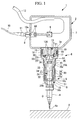
- Fig. 1 is a longitudinal section view showing a microscope examination apparatus according to a first embodiment of the present invention.
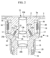
- Fig. 2 is a magnified partial cross-sectional view showing a support mechanism of the microscope examination apparatus in Fig. 1.
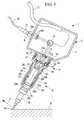
- Fig. 3 is a longitudinal sectional view showing a case where an external force acts on the tip of an objective lens unit in the microscope examination apparatus in Fig. 1.
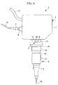
- Fig. 4 is a magnified partial cross-sectional view showing the support mechanism in the microscope examination apparatus in Fig. 3.
- Fig. 5 is a magnified partial cross-sectional view showing a first modification of the microscope examination apparatus in Fig. 1.
- Fig. 6 is an elevational view showing a second modification of the microscope examination apparatus in Fig. 1.
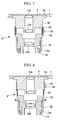
- Fig. 7 is a magnified partial cross-sectional view showing a third modification of the microscope examination apparatus in Fig. 1.
- Fig. 8 is a magnified partial cross-sectional view showing the operation of a support mechanism in the microscope examination apparatus in Fig. 7.
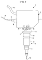
- Fig. 9 is an elevational view showing a fourth modification of the microscope examination apparatus in Fig. 1.
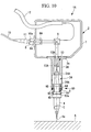
- Fig. 10 is a longitudinal sectional view showing a microscope examination apparatus according to a second embodiment of the present invention.
- Fig. 11 is a magnified partial cross-sectional view showing a support mechanism in the microscope examination apparatus in Fig. 10.
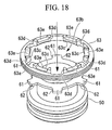
- Fig. 12 is a perspective view showing an objective-lens mounting member and an inner guard member constituting the support mechanism in Fig. 11.
- Fig. 13 is a perspective view showing the relationship between the objective-lens mounting member and the inner guard member when the objective lens unit is coupled to the base member, in the microscope examination apparatus shown in Fig. 10.
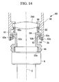
- Fig. 14 is a magnified partial longitudinal sectional view showing the support mechanism when the objective-lens mounting member is pushed in the axial direction relative to the base member.
- Fig. 15 is a perspective view showing the relationship between the objective-lens mounting member and the inner guard member in the state shown in Fig. 14.
- Fig. 16 is a perspective view showing a state where the objective-lens mounting member in Fig. 15 is rotated about its axis with respect to the inner guard member.
- Fig. 17 is magnified partial longitudinal sectional view showing the support mechanism when the objective-lens mounting member is separated from the base member.
- Fig. 18 is a perspective view showing the relationship between the objective-lens mounting member and the inner guard member in the state shown in Fig. 17.
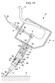
- Fig. 19 is a longitudinal sectional view showing a case where an external force acts on the tip of the objective lens unit in a direction intersecting the optical axis direction, in the microscope examination apparatus in Fig. 10.
- Fig. 20 is a magnified partial longitudinal sectional view showing the support mechanism of the microscope examination apparatus in the state shown in Fig. 19.
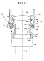
- Fig. 21 is a magnified longitudinal sectional view showing an example of a detector for detecting displacement of the objective-lens mounting member.
- Fig. 22 is a partial longitudinal sectional view for explaining attachment and detachment of the objective lens unit using a protector.
- Fig. 23 is a longitudinal section view showing a mechanism for preventing the objective lens unit from accidentally falling off.
- Figs. 24A, 24B, and 24C are magnified views for explaining the mechanism shown in Fig. 23, wherein Fig. 24A is a longitudinal sectional view when the mechanism is engaged, Fig. 24B is a longitudinal sectional view when the mechanism is released, and Fig. 24C is a plan view of the mechanism.
- Fig. 25 is a perspective view showing a microscope examination apparatus according to a third embodiment of the present invention.
- Fig. 26 is a perspective view illustrating examination of a specimen by the microscope examination apparatus in Fig. 25.
- Fig. 27 is a perspective view showing the microscope examination apparatus in Fig. 25 when the objective lens is retracted in the optical axis direction.
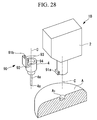
- Fig. 28 is a perspective view showing the microscope examination apparatus in Fig. 25 when the objective lens is removed.
- Fig. 29 is a perspective view showing a microscope examination apparatus according to a fourth embodiment of the present invention when examining a specimen.
- Fig. 30 is a perspective view showing the microscope examination apparatus in Fig. 29 when the objective lens is removed.
- Fig. 31 is a perspective view showing a microscope examination apparatus according to a fifth embodiment of the present invention when examining a specimen.
- Fig. 32 is a perspective view showing the microscope examination apparatus in Fig. 31 when the objective lens is removed.
- Fig. 33 is a perspective view showing a modification of the microscope examination apparatus in Fig. 31.
- Fig. 34 is a perspective view showing a microscope examination apparatus according to a sixth embodiment of the present invention when examining a specimen.
- Fig. 35 is a perspective view showing the microscope examination apparatus in Fig. 34 when the objective lens is removed.
- a microscope examination apparatus 1 according to a first embodiment of the present invention will be described below with reference to Figs. 1 to 4.
- the microscope examination apparatus 1 of this embodiment is used to examine the interior of a specimen A, which is a living organism such as small laboratory animal, like a mouse.
- the microscope examination apparatus 1 includes an apparatus main body (microscope main body) 2, a base member 3 which is secured to the apparatus main body 2, an objective-lens mounting member 5, disposed in contact with the base member 3, for mounting an objective lens unit 4 so as to enable attachment and detachment thereof, and a support mechanism 6 for supporting the objective-lens mounting member 5 relative to the base member 3.
- the apparatus main body 2 includes a main body case 7, a collimator unit 8 which is secured to the main body case 7, and an optical scanning unit 9 for two-dimensionally scanning light collimated by the collimator unit 8.
- an optical fiber 10 that guides light from a light source is secured to the collimator unit 8 with a connector 11.
- the connector 11 is fixed to the collimator unit 8 so as to be slightly inclined relative to the optical axis.
- This provides a structure in which a light-emitting face 10a of the optical fiber 10 is formed at an incline with respect to the longitudinal direction, which prevents light reflected inside the optical fiber 10 at the light-emitting face 10a from returning to an optical detector (not shown) provided at the light source side.
- Light emitted from the light-emitting face 10a of the optical fiber 10 is converged upon passing through lenses 8A in the collimator unit 8 and is converted to a collimated beam.
- the optical scanning unit 9 is formed of so-called proximity galvanometer mirrors in which two galvanometer mirrors (not shown in the drawing) that are supported so as to be capable of oscillating back and forth about two mutually orthogonal axes thereof are disposed adjacent to each other.
- Each galvanometer mirror can be oscillated back and forth at a predetermined speed by actuators (not shown in the drawing), based on control signals sent from an external control unit (not shown) via a cable 12. Accordingly, the collimated beam is two-dimensionally scanned.
- the base member 3 includes a substantially cylindrical flange 3a for securing the base member 3 to the main body case 7. Also, the base member 3 includes a pupil-projection lens unit 13 formed of a plurality of lenses 13A for focusing the light scanned by the optical scanning unit 9 to form an intermediate image. A spherical surface 14 that contacts the objective-lens mounting member 5 is provided at one end of the base member 3.
- the objective-lens mounting member 5 includes a first cylindrical portion 15 disposed in contact with the base member 3 and a second cylindrical portion 16 which is fitted to the outer side of the first cylindrical portion 15 so as to be capable of moving in the axial direction.
- the first cylindrical portion 15 has an inner spherical surface 17 having a shape that is complementary with the spherical surface 14 of the base member 3.
- the support mechanism 6 includes the spherical surface 14 provided in the base member 3, the inner spherical surface 17 provided in the first cylindrical portion 15, and urging members formed of a plurality of coil springs 18 disposed so as to bridge the base member 3 and the first cylindrical portion 15.
- the coil springs 18 are provided, for example, at three uniformly-spaced locations around the circumference of the base member 3.
- Reference numerals 19 are shafts for attaching the coil springs 18, and reference numeral 20 is a cover for covering the coil springs 18.
- Reference numeral 26 is a stopper against which the first cylindrical portion 15 abuts when rotated by a predetermined angle with respect to the base member 3.
- a click mechanism 23 is disposed between the spherical surface 14 and the inner spherical surface 17, which are in contact with each other.
- the click mechanism 23 is formed of a plurality of ball plungers 21 and indentations 22 which engage at the position where the central axis of the base member 3 and the central axis of the first cylindrical portion 15 are aligned.
- the ball plungers 21 are formed of balls 21b which are movably accommodated inside guide holes 21a that extend in the radial direction from the spherical surface 14, and springs 21c that urge the balls 21b towards the outside in the radial direction.
- the balls 21b of the ball plungers 21 are urged by the springs 21c so as to protrude from the guide holes 21a and engage with the indentations 22 in the inner spherical surface 17. This allows the first cylindrical portion 15 to be locked relative to the base member 3 with a locking force that corresponds to the urging force of the springs 21c.
- the first cylindrical portion 15 is provided with an image-forming lens unit 24 having an image-forming lens 24A for collecting and imaging the light forming the intermediate image of the pupil-projection lens unit 13.
- a guard portion 16a that extends in the outer radial direction is provided at one end of the second cylindrical portion 16.
- a threaded portion 16b for securing the objective-lens unit 4 is provided at the other end of the second cylindrical portion 16.
- a holder 25 that engages with the guard portion 16a of the objective-lens mounting member 5 is secured to the first cylindrical portion 15.
- a threaded hole 27 is provided in the outer surface of the first cylindrical portion 15 in the radial direction.
- An elongated hole 28 that extends a predetermined length in the axial direction is formed in the second cylindrical portion 16 at a position corresponding to the threaded hole 27.
- a bolt 29 is screwed into the threaded hole 27 via this elongated hole 28.
- the elongated hole 28 has a width dimension that is slightly larger than the diameter of the head of the bolt 29. Therefore, the head of the bolt 29 is capable of relative motion in the axial direction inside the elongated hole 28, whereas relative motion between the elongated hole 28 and the bolt 29 in the circumferential direction is prevented. This constitutes a rotation-locking mechanism 30.
- reference numeral 31 indicates a cover member for covering the head of the bolt 29 and the elongated hole 28.
- the cover member 31 is formed of rubber, for example; gripping it when attaching and detaching the objective lens unit 4 facilitates attachment and detachment because the objective-lens mounting member 5, to which the objective lens unit 4 is mounted, can be held without slipping.
- the cover member 31 completely covers the elongated hole 28 provided in the second cylindrical portion 16 and prevents dust from getting into the elongated hole 28. In addition, covering the elongated hole 28 and the bolt 29 improves the external appearance.
- Stepped portions 15a and 16c which are disposed opposite each other in the axial direction around the entire circumference, are formed in the outer surface of the first cylindrical portion 15 and the inner surface of the second cylindrical portion 16.
- a coil spring 32 is sandwiched between these stepped portions 15a and 16c. Even when the distance between the stepped portions 15a and 16c is at its widest, the coil spring 32 is compressed by a certain amount so that it always urges in a direction that widens the distance between the stepped portions 15a and 16c.
- the objective-lens mounting member 5 is urged in a direction towards the front end thereof by the urging force of the coil spring 32. Because the guard portion 16a provided at the rear end thereof abuts against the holder 25, displacement past a certain point towards the front end along the optical axis C is restricted, and the objective-lens mounting member 5 can thus be precisely located at that position.
- the second cylindrical portion 16 to which the objective lens unit 4 is mounted moves relative to the first cylindrical portion 15 so that it is pushed backwards along the optical axis C.
- the second cylindrical portion 16 is displaced with respect to the first cylindrical portion 15 along the optical axis C so as to change the optical path length at position B of the substantially collimated beam emitted from the image-forming lens unit 24.
- a female thread 33 is formed to pass through the second cylindrical portion 16 in the radial direction, and an indentation 34 is formed in the first cylindrical portion 15 at a position aligned with the female thread 33 when the objective-lens mounting member 5 is disposed at the front-most end.
- a fastening member (not shown in the drawing) is engaged with the female thread 33 from the outside, and the tip thereof can be located in the indentation 34.
- the fastening member has a male thread at the tip that engages with the female thread 33 and a knob that is gripped for engaging the male thread, and it may be attached to the main body case 7 by a chain or the like.
- an arm (not shown) for supporting the apparatus main body 2 is operated to set a desired position and orientation of the apparatus main body 2. Then, an incision is made in the specimen A, which is a living organism such as a laboratory animal, and the tip 4a of the objective lens unit 4 is inserted into the opening.
- the invention is not limited to the case of an incision made in the specimen A, however; the microscope examination apparatus 1 according to this embodiment may also be used to carry out external examination without making an incision in thin skin, such as that of the ear, for example.
- the apparatus main body 2 is fixed at the desired position, excitation light, for example, laser light, is supplied from a light source (not shown in the drawing), and the optical scanning unit 9 is operated.
- excitation light for example, laser light
- the excitation light emitted from the light source propagates in the optical fiber 10 and is then guided inside the apparatus main body 2 via the connector 11.
- the collimator unit 8 is fixed to the apparatus main body 2, the excitation light emitted inside the main body case 7 from the light-emitting face 10a of the optical fiber 10 is converted to a collimated beam upon passing through the lenses 8A in the collimator unit 8.
- the collimated excitation light is then incident on the optical scanning unit 9.
- the optical scanning unit 9 deflects the excitation light by 90° (in Fig. 1, horizontally incident excitation light is deflected vertically), and the excitation light is two-dimensionally scanned.
- the scanned excitation light forms an intermediate image upon passing through the pupil-projection lens unit 13 and is thereafter converted to a collimated beam upon passing through the image-forming lens unit 24.
- the collimated beam emitted from the image-forming lens unit 24 is introduced to the objective lens unit 4 and is re-imaged at a focal point a predetermined working distance in front of the tip 4a thereof.
- the excitation light When the excitation light is incident on the specimen A, fluorescent material present inside the specimen A becomes excited and generates fluorescence.
- the fluorescence generated returns back inside the objective lens unit 4 from the tip 4a of the objective lens unit 4, passes through the image-forming lens unit 24, the pupil-projection lens unit 13, the optical scanning unit 9, and the collimator unit 8, enters the optical fiber 10, and returns to the light source side.
- the fluorescence is split-off from the excitation light by a dichroic mirror (not shown in the drawing) and is detected by a optical detector (not shown), for example, a photomultiplier tube (PMT). Then, the detected fluorescence is converted to an image and is displayed on a monitor.
- a dichroic mirror not shown in the drawing
- PMT photomultiplier tube
- the optical fiber 10 has a sufficiently small core diameter, such as a single-mode fiber, the end of the optical fiber 10 is in a conjugate positional relationship with the image position of the tip 4a of the objective lens unit 4, thus constituting a confocal optical system.
- a confocal optical system since only fluorescence light produced close to the image position of the tip 4a of the objective lens unit 4 enters the optical fiber 10, and therefore, a high resolution image can be obtained.
- the optical fiber 10 has a larger core diameter, although the resolution is degraded, it is still possible to obtain bright images having depth.
- the apparatus main body 2 and the objective lens unit 4 are moved, while viewing the obtained image, in the direction of the optical axis C thereof to search for a desired examination site, the image position of the excitation light moves in the direction of the optical axis C. As a result, it is possible to change the examination position in the depth direction.
- the microscope examination apparatus 1 because a shock-absorbing mechanism including the coil spring 32 described above is provide in the apparatus main body 2 instead of in the vicinity of the tip 4a of the objective lens unit 4, the construction at the tip 4a of the objective lens 4 can be simplified and the diameter can be reduced. Therefore, when examining the interior of the specimen A, such as a living organism, it is possible to keep the size of the incision for inserting the tip 4a of the objective lens unit 4 to the absolute minimum.
- the stress placed to the specimen A can be reduced, and the viability of the specimen A can be maintained for a long period of time.
- the tip 4a of the objective lens unit 4 is inserted in the specimen A, such as a living organism, it is possible to continue to perform in-vivo examination of the living organism for a long period of time.
- the microscope examination apparatus 1 which is not provided with the shock-absorbing mechanism in the objective lens unit 4, when replacing the objective lens unit 4 with another one having a different magnification or tip shape and attaching it to the objective-lens mounting member 5, it is not necessary to provide a shock-absorbing mechanism in each objective lens unit 4. Therefore, an advantage is afforded in that it is possible to reduce the overall cost of the apparatus.
- no movable parts for the shock-absorbing mechanism are provided in the objective lens unit 4, it is possible to easily make the objective lens unit 4 waterproof. Therefore, it is possible to provide a microscope examination apparatus 1 that is suitable for performing examination while the tip 4a of the objective lens unit 4 is inserted inside the specimen A, which includes liquid such as bodily fluids.
- the microscope examination apparatus 1 when the objective lens unit 4 is displaced relative to the apparatus main body 2, the optical path length at the position B of the collimated beam emitted from the image-forming lens unit 24 is changed. Therefore, even if the objective lens unit 4 is displaced in the direction of the optical axis C, its imaging relationship does not change.
- the specimen A is a living organism such as a mouse or the like
- the microscope examination apparatus 1 when performing in-vivo examination of the living organism, the surface of the specimen A moves due to the heart beat, pulsation of blood vessels, respiration, and so forth.
- the tip 4a of the objective lens unit 4 is pressed against the specimen A, and examination is carried out at the position where the objective lens unit 4 is slightly pushed back towards the apparatus main body 2.
- the objective lens unit 4 can be attached and detached at the position B of the collimated beam output from the image-forming lens unit 24, the objective lens unit 4 is an infinity optical system. Therefore, by designing the threaded portion 16b of the objective-lens mounting member 5 to have the gauge used in standard microscopes, it is possible to attach and detach a standard microscope objective lens unit.
- the head of the bold 29 fastened to the first cylindrical portion 15 is located inside the elongated hole 28 formed in the second cylindrical portion 16 to prevent rotation of the objective lens unit 4 in the circumferential direction relative to the apparatus main body 2. Therefore, it is possible to prevent variations in the optical characteristics of the entire apparatus due to the objective lens unit 4 rotating relative to the image-forming lens unit 24. Also, when attaching and detaching the objective lens unit 4 to and from the threaded portion 16b provided on the objective-lens unit mounting member 5, because the objective-lens unit mounting member 5 is prevented from rotating, an advantage is afforded in that attachment and detachment of the objective lens unit 4 can be performed more efficiently.
- the microscope examination apparatus 1 by fastening the fastening member with the female thread 33 provide in the second cylindrical portion 16, it is possible to secure the objective lens unit 4 so that it does not shift in the direction of the optical axis C relative to the apparatus main body 2.
- the shock-absorbing mechanism does not operate. This is convenient in applications where it is preferable not to operate the shock-absorbing mechanism.
- the objective lens unit 4 when the objective lens unit 4 is attached to and detached from the objective-lens mounting member 5, it is better to stop the operation of the shock-absorbing mechanism and fix the objective-lens mounting member 5 to make it easier to attach and detach the objective lens unit 4.
- the tip 4a of the objective lens unit 4 backwards in the opposite direction to the external force F, it is possible to prevent an excessively large pressing force from being applied to the tip 4a, and it is thus possible to prevent damage to the objective lens unit 4 and the specimen A.
- the stopper 26 is provided in the base member 3, when the first cylindrical portion 15 abuts against the stopper 26, the first cylindrical portion 15 is prevented from rotating past a predetermined point with respect to the base member 3. Therefore, it is possible to prevent an excessively large pressing force from being exerted on the tip 4a of the objective lens unit 4, and it is possible to ensure that the objective-lens mounting member 5 to which the objective lens unit 4 is attached does not come off the base member 3.
- the microscope examination apparatus 1 because the base member 3 and the first cylindrical portion 15 are in close contact via the spherical surface 14 and the inner spherical surface 17, it is possible to ensure positional accuracy in the direction of the optical axis C. Therefore, by releasing the click mechanism 23, even if the central axis of the base member 3 and the central axis of the first cylindrical portion 15 are shifted, it is possible to duplicate the positional accuracy in the direction of the optical axis C when they are returned to the positions where their central axes are aligned.
- the support mechanism 6 has the spherical surface 14 and the inner spherical surface 17, even if an external force F acts on the tip 4a of the objective lens unit 4 in any direction intersecting the optical axis C, the objective lens unit 4 can be made to rotate in a direction away from that force F. Therefore, it is possible to prevent damage to the objective lens unit 4 as well as to the specimen A in contact therewith.
- a plurality of the coil springs 18 are disposed around the base member 3; instead of this, however, as shown in Fig. 5, a single coil spring 18' may be disposed so as to surround the periphery of the base member 3.
- the spherical surface 14 is provided in the base member 3 and the inner spherical surface 17 is provided in the first cylindrical portion 15, instead of this configuration, the spherical surface 14 may be provided in the first cylindrical portion 15 and the spherical surface 17 may be provided in the base member 3. Furthermore, although the ball plungers 21 are provided in the spherical surface 14 and the indentations are provided in the spherical surface 17, the opposite is also acceptable.
- the support mechanism 6 includes the spherical surface 14 and the inner spherical surface 17, which are in close contact with each other.
- it may include a cylindrical surface and a cylindrical inner surface in close contact with each other.
- the direction of rotation of the first cylindrical portion 15 with respect to the base member 3 is restricted to one direction; however, when the tilt direction of the microscope examination apparatus 1 with respect to the specimen A or a stage is regulated, by matching the rotation direction to that tilt direction, it is possible to effectively prevent the generation of an excessive pressing force on the tip 4a of the objective lens unit 4, similar to the case described above.
- a support mechanism 6' that supports the first cylindrical portion 15 in such a manner that it is capable of rotating relative to the base member 3 by means of a shaft 40.
- Click mechanisms 41 formed, for example, of ball plunger, indentations, and so forth may be disposed at positions away from the shaft 40.
- a support mechanism 6 formed by coupling the base member 3 and the first cylindrical portion 15 using a flexible member, such as relatively stiff bellows 42.
- a slidable correcting tube 43 is provided on the base member 3.
- the correcting tube 43 is disposed at a position where it encircles the outer surface of the bellows 42, thus correcting the flexing of the bellows 42 to form a straight line.
- the correcting tube 43 is retracted to the base member 3 side.
- Reference numeral 44 in Figs. 7 and 8 is a locking screw for fixing the correcting tube 43 to the base member 3.
- sensors 45 may be provided between the base member 3 and the first cylindrical portion 15 for detecting the relative rotation thereof.
- a plurality of the sensors 45 should be provided in the direction in which the first cylindrical portion 15 swings with respect to the base member 3.
- the sensors 45 may be proximity sensors, for example. Instead of proximity sensors, micro switches which detect contact between the objective lens unit 4 and the specimen A based on a detection signal may be used.
- a microscope examination apparatus 1A according to a second embodiment of the present invention will be described with reference to Figs. 10 to 20. Parts identical to those in the embodiment described above are assigned the same reference numerals, and a description thereof will thus be omitted here.
- the microscope examination apparatus 1A includes an apparatus main body 2, a base member 3A which is secured to the apparatus main body 2, an objective lens unit 4, an objective-lens mounting member 50 mounted to the objective lens unit 4, and a support mechanism 60 for supporting the objective-lens mounting member 50 relative to the base member 3A.
- the base member 3A includes a substantially cylindrical flange 3a for securing to a main body case 7.
- the base member 3A includes a pupil-projection lens unit 13 formed of a plurality of lenses 13A for focusing light scanned by an optical scanning unit 9 to form an intermediate image.
- the base member 3A also includes a lens unit 24 having an image-forming lens 24A for collecting and collimating the light forming the intermediate image of the pupil-projection lens unit 13.
- the objective-lens mounting member 50 of this embodiment is a substantially cylindrical member having a female threaded portion 50a for engaging with a mounting thread 4b provided on the objective lens unit 4.
- the objective-lens mounting member 50 is provided with outer guard portions 61 constituting part of the support mechanism 60 (described later).
- the outer guard portions 61 are provided at the end opposite the female threaded portion 50a and project outwards in the radial direction at six locations which are uniformly spaced in the circumferential direction. Notches 62 are formed between these guard portions 61.
- the support mechanism 60 includes the outer guard portions 61 provided in the objective-lens mounting member 50, an inner guard member 63 attached at the end of the base member 3A, a ring-shaped support plate 64 which covers the inner side of the guard member 63 in the axial direction, and a coil spring (urging member) 65 for urging the support plate 64 in the axial direction.
- the inner guard member 63 has a male threaded portion 63a for engaging with the female threaded portion 3b provided at the end of the base member 3A and is secured to the end of the base member 3A by engaging the male threaded portion 63a with the female threaded portion 3b.
- the inner guard member 63 is formed in the shape of a ring having a central through-hole 63b and includes inner guard portions 63c that extend inwards in the radial direction at six uniformly spaced locations in the circumferential direction and notches 63d provided between these inner guard portions 63c.
- the central through hole 63b in the inner guard member 63 is formed with dimensions that allow the outer guard portions 61 of the objective-lens mounting member 50 to pass therethrough.
- the outer guard portions 61 of the objective-lens mounting member 50 can pass through the notches 63d in the inner guard member 63 in the axial direction
- the inner guard portions 63c can pass through the notches 62 between the outer guard portions 61 in the axial direction.
- indentations (locking mechanisms) 63e having width dimensions larger than the width dimensions of the outer guard portions 63 are provided at central positions in the circumferential direction on the end face disposed inside the base member 3A.
- the outer guard portions 61 of the objective-lens mounting member 50 are accommodated in the corresponding indentations 63e provided in the inner guard portions 63c, as shown in Fig. 11.
- a guide face 50b which progressively widens in the axial direction towards the outer guard portions 61 is provided on the objective-lens mounting member 50, inside the outer guard portions 61 in the radial direction.
- the maximum diameter of the guide face 50b is substantially the same as the inner diameter of the through-hole 63 in the inner guard member 63.
- the objective-lens mounting member 50 when the objective-lens mounting member 50 is coupled with the base member 3A, the objective-lens mounting member 50 is pressed by the coil spring 65, which presses the support plate 64, and the maximum-diameter position of the guide surface 50b thereof is fitted into the central through-hole 63b. Therefore, the optical axis of the base member 3A and the optical axis C of the objective lens unit 4 can be accurately aligned.
- the support plate 64 is brought into contact with the end surface of the outer guard member 63 in the axial direction. If the objective-lens mounting member 50 is pushed in this state so that it is inserted further inside the base member 3A, the coil spring 65, which pushes the support plate 64, is compressed, and the support plate 64 moves in the axial direction.
- reference numeral 66 is a ring nut for securing the image-forming lens 24A, and support indentations 66a for supporting one end of the coil spring 65 are provided in the end face of the ring nut 66.
- an arm (not shown) for supporting the apparatus main body 2 is moved to set the apparatus main body 2 at a desired position and orientation. Then, an incision is made in a specimen A, which is a living organism such as a laboratory animal, and the tip 4a of the objective lens unit 4 is inserted into the opening.
- a specimen A which is a living organism such as a laboratory animal
- the invention is not limited to the case of an incision made in the specimen A, however; the microscope examination apparatus 1A according to this embodiment may also be used to carry out external examination without making an incision in thin skin, such as that of the ear, for example.
- the apparatus main body 2 is fixed at the desired position, excitation light, for example, laser light, is supplied from a light source (not shown in the drawing), and the optical scanning unit 9 is operated.
- excitation light for example, laser light
- the excitation light emitted from the light source propagates in the optical fiber 10 and is then guided inside the apparatus main body 2 via the connector 11.
- the collimator unit 8 is fixed to the apparatus main body 2, the excitation light emitted inside the main body case 7 from the light-emitting face 10a of the optical fiber 10 is converted to a collimated beam upon passing through the lenses 8A in the collimator unit 8.
- the collimated excitation light is then incident on the optical scanning unit 9.
- the optical scanning unit 9 deflects the excitation light by 90° (in Fig. 10, horizontally incident excitation light is deflected vertically), and the excitation light is two-dimensionally scanned.
- the scanned excitation light forms an intermediate image upon passing through the pupil-projection lens unit 13 and is thereafter converted to a collimated beam upon passing through the lens unit 14.
- the collimated beam emitted from the lens unit 14 is introduced to the objective lens unit 4 and is re-imaged at a focal point a predetermined working distance in front of the tip 4a thereof.
- the excitation light When the excitation light is incident on the specimen A, fluorescent material present inside the specimen A becomes excited and generates fluorescence.
- the fluorescence generated returns back inside the objective lens unit 4 from the tip 4a of the objective lens unit 4, passes through the lens unit 24, the pupil-projection lens unit 13, the optical scanning unit 9, and the collimator unit 8, enters the optical fiber 10, and returns to the light source side.
- the fluorescence is split-off from the excitation light by a dichroic mirror (not shown in the drawing) and is detected by an optical detector (not shown), for example, a photomultiplier tube (PMT) . Then, the detected fluorescence is converted to an image and is displayed on a monitor.
- PMT photomultiplier tube
- the optical fiber 10 has a sufficiently small core diameter, such as a single-mode fiber, the end of the optical fiber 10 is in a conjugate positional relationship with the image position of the tip 4a of the objective lens unit 4, thus constituting a confocal optical system.
- a confocal optical system since only fluorescence light produced close to the image position of the tip 4a of the objective lens unit 4 enters the optical fiber 10, and therefore, a high resolution image can be obtained.
- the optical fiber 10 has a larger core diameter, although the resolution is degraded, it is still possible to obtain bright images having depth.
- the apparatus main body 2 and the objective lens unit 4 are moved, while viewing the obtained image, in the direction of the optical axis C thereof to search for a desired examination site, the image position of the excitation light moves in the direction of the optical axis C. As a result, it is possible to change the examination position in the depth direction.
- the shock-absorbing mechanism including the coil spring 65 mentioned above is provided at the base member 3A side, which is fixed to the apparatus main body 2, instead of in the vicinity of the tip 4a of the objective lens unit 4, the construction at the tip 4a of the objective lens unit can be simplified and the diameter can be reduced. Therefore, when examining the interior of the specimen A, such as a living organism, it is possible to keep the size of the incision for inserting the tip 4a of the objective lens unit 4 to the absolute minimum.
- the load applied to the specimen A can be reduced, and the viability of the specimen A can be maintained for a long period of time.
- the tip 4a of the objective lens unit 4 is inserted in the specimen A, such as a living organism, it is possible to continue to perform in-vivo examination of the living organism for a long period of time.
- the microscope examination apparatus 1A which is not provided with the shock-absorbing mechanism in the objective lens unit 4, when replacing the objective lens unit 4 with another one having a different magnification or tip shape, because it is not necessary to provide a shock-absorbing mechanism in each objective lens unit 4, an advantage is afforded in that it is possible to reduce the overall cost of the apparatus.
- no movable parts for the shock-absorbing mechanism are provided in the objective lens unit 4, it is possible to easily make the objective lens unit 4 waterproof. Therefore, it is possible to provide a microscope examination apparatus 1A that is suitable for performing examination while the tip 4a of the objective lens unit 4 is inserted inside a specimen A which includes liquid such as bodily fluids.
- the microscope examination apparatus 1A when the objective lens unit 4 is displaced relative to the apparatus main body 2, the optical path length at the position B of the collimated beam emitted from the image-forming lens unit 24 is changed. Therefore, even if the objective lens unit 4 is displaced in the direction of the optical axis C, its imaging relationship does not change.
- the specimen A is a living organism such as a mouse or the like
- the microscope examination apparatus 1A when performing in-vivo examination of the living organism, the surface of the specimen A moves due to the heart beat, pulsation of blood vessels, respiration, and so forth.
- the tip 4a of the objective lens unit 4 is pressed against the specimen A, and examination is carried out at the position where the objective lens unit 4 is slightly pushed back towards the apparatus main body 2.
- the objective lens unit 4 can be attached and detached at the position B of the collimated beam output from the image-forming lens unit 24, the objective lens unit 4 is an infinity optical system. Therefore, by designing the female threaded portion 50a of the objective-lens mounting member 50 to have the gauge used in standard microscopes, it is possible to attach and detach a standard microscope objective lens unit.
- the support plate 64 is pressed and the coil spring 65 is compressed, and as shown in Fig. 15, the outer guard portions 61 of the objective-lens mounting member 50 move in the axial direction to a position where they come out of the indentations 63e in the inner guard portions 63c.
- the objective-lens mounting member 50 can be relatively rotated about the axial line with respect o the inner guard member 63, as indicated by the arrows in Fig. 15.
- the outer guard portions 61 become aligned with the notches 63d of the inner guard member 63 and the inner guard portions 63c become aligned with the notches 62 between the outer guard portions 61. Therefore, by moving the objective-lens mounting member 50 in the axial direction as indicated by the arrow, the guard portions 61 are extracted from the inner guard member 63, and it is possible to disengage the objective-lens mounting member 50 and the base member 3A, as shown in Figs. 17 and 18.
- the microscope examination apparatus 1A simply by rotating the objective-lens mounting member 50 by 30° about the axial line while it is slightly pushed in the axial direction relative to the base member 3A, it is possible to remove it from the base member 3A while keeping the objective lens unit 4 mounted to the objective-lens mounting member 50.
- the objective lens unit 4 can be attached to the base member 3A, while mounted to the objective-lens mounting member 50, simply by performing the above described procedure in reverse.
- the microscope examination apparatus 1A in an examination location where the working space is limited, it is not necessary to carry out an attaching procedure involving rotating the fine threaded mount 4b about the axis multiple times to engage it with the female threaded portion 50a.
- the objective lens unit 4 can be attached and detached in an extremely simple fashion, merely by pushing and rotating it by 30°. As a result, an advantage is afforded in that it is possible to drastically improve the efficiency of the procedure for replacing the objective lens unit 4.
- the objective lens unit 4 can be removed from the objective-lens mounting member 50 by loosening the threaded mount 4b of the objective lens unit 4. Since this procedure can be carried out in a comparatively larger working space away from the examination site, there is less of a burden on the operator.
- the support plate 64 is pushed back by the urging force of the coil spring 65, is guided by the guide surface 50b provided in the objective-lens mounting member 50 so that it fits in the central through-hole 63b in the inner guard member 63, and the objective lens unit 4 thus returns to a position where the optical axis C' of the base member 3A and the optical axis C of the objective lens unit 4 are aligned.
- the inner guard member 63 is fixed to the base member 3A and the outer guard portions 61 are provided in the objective-lens mounting member 50; conversely, however, the outer guard portions 61 may be provided in the base member 3A and the inner guard member 63 may be provided in the objective-lens mounting member 50.
- the detector 70 for detecting when the objective-lens mounting member 50 is shifted relative to the base member 3A.
- the detector 70 may be formed, for example, of a light-emitting unit 71 and a light-receiving unit 72 disposed next to each other outside the base member 3A, a through-hole 73 disposed in the base member 3A so as to pass light from the light-emitting unit 71, and a mirror 74 fixed to the support plate 64.
- the detector 70 By providing such a detector 70, it is possible to detect that the objective-lens mounting member 50 is displaced relative to the base member 3A, in other words, that an external force is exerted on the objective-lens unit 4. Therefore, by stopping the motion of the objective lens unit based on the detection signal or by loosening the objective lens unit 4 in a direction that lessens the external force, it is possible to protect the specimen A and the tip 4a of the objective lens unit 4 so that they are not damaged.
- the detector 70 is not limited to the optical type described above; any other type of detector may be used, not just a micro switch.
- the detector 70 In order for the detector 70 to detect tilting of the objective lens unit 4 in all directions with respect to the base member 3A, it is preferable to provide a plurality of them at intervals in the circumferential direction of the base member 3A.
- a protector 75 is formed in the shape of a substantially cylindrical tube that surrounds the objective lens unit 4 from the tip 4a side, and one end thereof is closed off.
- an abutting surface 75a for abutting with a stepped portion 4c of the objective lens unit 4 is provided, and projections 75b for engaging with indentations 4d provided in the stepped portion 4c of the objective lens unit 4 are provided in the abutting surface 75a.
- a plurality of the projections 75b and indentations 4d are provided at intervals in the circumferential direction.
- the protector 75 is fitted to the objective lens unit 4, and the projections 75b in the abutting surface 75a are engaged with the indentations 4d in the stepped portion 4c of the objective lens unit 4.
- the protector 75 rotates it while pushing the objective-lens mounting member 50 into the base member 3A, the operator can attach and detach the objective-lens unit 4 without directly touching the objective lens unit 4.
- a mechanism 80 may be provided for preventing the objective lens unit 4 from accidentally falling off.
- This mechanism 80 includes, for example, an outer link 81 and an inner link 82 which are attached so as to be capable of oscillating back and forth, an intermediate link 83 for coupling these links 81 and 82, and an engaging groove 84 which can engage with the end of the inner link 82; all of these components are provided at the end of the base member 3A.
- the outer link 81 and the inner link 82 are urged in the state shown in Fig. 24A by a spring 85.
- the optical apparatus 1B which is a microscope examination apparatus (hereinafter referred to as microscope examination apparatus 1B), includes an apparatus (microscope) main body 2, an objective lens unit 4, and an objective-lens mounting mechanism 90.
- microscope examination apparatus 1B includes an apparatus (microscope) main body 2, an objective lens unit 4, and an objective-lens mounting mechanism 90.
- an optical fiber for guiding excitation light from a light source device is connected to the apparatus main body 2.
- a collimator unit for collecting excitation light emitted from the optical fiber and converting it to a substantially collimated beam
- an optical scanning unit for two-dimensionally scanning the substantially collimated excitation light
- a pupil-projection lens unit for focusing the excitation light scanned by the optical scanning unit to form an intermediate image
- an image-forming lens unit for collecting the excitation light forming the intermediate image and turning it into a substantially collimated beam.
- an optical detector for detecting fluorescence from a specimen A (see Fig. 26), which is collected through the objective lens unit 4, and the optical detector is connected to the apparatus main body 2 via an optical fiber.
- a monitor is provided for displaying a fluorescence image constructed on the basis of the fluorescence detected by the optical detector.
- the excitation light transmitted from the light source device is two-dimensionally scanned and introduced to the objective lens unit 4; the two-dimensionally scanned excitation light is then emitted from the tip 4a of the objective lens unit 4.
- the fluorescence from the specimen A, which is collected via the objective lens unit 4 is detected by the optical detector, and a fluorescence image is displayed on the monitor.
- the apparatus main body is attached to an arm provided with a focusing unit (not shown). By operating the focusing unit, it is possible to fix the apparatus main body 2 at a desired position and orientation within an adjustable range.
- the objective lens unit 4 includes a small-diameter end portion 4e whose tip 4a can be inserted inside the body of a living organism, serving as the specimen A, with minimal invasiveness.
- the objective-lens mounting mechanism 90 includes an objective-lens advancing-and-retracting mechanism 91 for advancing and retracting the tip 4a of the objective lens unit 4 in the direction of the optical axis C thereof, and an attaching-and-detaching mechanism 92 for attaching and detaching the objective lens unit 4 to and from the apparatus main body 2 when the tip 4a of the objective lens unit 4 is retracted in the direction of the optical axis C.
- the objective-lens advancing-and-retracting mechanism 91 includes a dovetail tenon 91a fixed to the apparatus main body 2 and a dovetail groove 91b fixed to the objective lens unit 4.
- a stopper 93 and a plunger 94 are provided in the dovetail groove 91b.
- the stopper 93 abuts against the end face of the dovetail tenon 91a when the tip 4a of the objective lens unit 4 is fully forward, and the plunger 94 presses against the outer surface of the dovetail tenon 91a at the inner surface of the dovetail groove 91b to prevent positional shifting of the dovetail groove 91b and the dovetail tenon 91a due to a gap when fitting them together.
- the dovetail groove 91b extends substantially parallel to the optical axis C and guides the dovetail tenon 91a, which is fitted with the dovetail groove 91b, in the direction of the optical axis C along the dovetail groove 91b.
- the distance that the dovetail groove 91b can move along the dovetail tenon 91a is set to be longer than the insertion depth of the objective lens unit 4 inside an indentation A 1 in the specimen A.
- the attaching-and-detaching mechanism 92 is formed of a notch (hereinafter referred to as notch 92) provided in the dovetail groove 91b at the tip 4a side of the objective lens unit 4.
- notch 92 a notch
- the attaching-and-detaching mechanism 92 is formed of a notch (hereinafter referred to as notch 92) provided in the dovetail groove 91b at the tip 4a side of the objective lens unit 4.
- the objective lens unit 4 which has a low magnification, is attached to the apparatus main body 2 with the objective-lens mounting mechanism 90, the focusing unit is operated to advance the objective lens unit 4 in the direction of the optical axis C, and as shown in Fig. 26, the tip 4a of the objective lens unit 4 is inserted in the indentation A 1 in the specimen A (shown in cross section) ready for examination.
- the excitation light is two-dimensionally scanned inside the apparatus main body 2 and is emitted from the tip 4a of the objective lens unit 4 towards the specimen A. Due to irradiation with the excitation light, fluorescent material in the specimen A is excited and generates fluorescence. The fluorescence generated is collected by the objective lens unit 4, returns along the reverse path, is detected by the optical detector, and is displayed on the monitor. The operator operates the focusing unit while looking at the monitor display to align the center of the objective lens unit 4 with the site to be examined and fixes the focusing unit in this state.
- the objective-lens mounting mechanism 90 is operated while keeping the focusing unit fixed. More specifically, as indicated by the arrow Z in Fig. 27, the dovetail groove 91b provided on the objective lens unit 4 is moved along the optical axis C relative to the dovetail tenon 91a provided in the apparatus main body 2. By doing so, the tip 4a of the objective lens unit 4 is retracted from the indentation A 1 in the specimen A in the direction of the optical axis C.
- the dovetail groove 91b has moved by a predetermined distance relative to the dovetail tenon 91a so that the notch 92 provided in the dovetail groove 91b is aligned with the dovetail tenon 91a, the dovetail groove 91b and the dovetail tenon 91a are disengaged. Therefore, it is possible to move the dovetail groove 92b relative to the dovetail tenon 91a in the direction perpendicular to the optical axis C. Accordingly, as shown in Fig. 28, the objective lens unit 4 whose tip 4a has been removed from the indentation A 1 in the specimen A can be moved in a direction perpendicular to the optical axis C, and it is thus possible to easily remove the objective lens unit 4 from the apparatus main body 2.
- a high-magnification objective lens unit 4 is prepared, the notch 92 in the dovetail groove 91b provided in this objective lens unit 4 is positioned at the dovetail tenon 91a in the apparatus main body 2 to align the optical axis C of the objective lens unit 4 and the optical axis C of the apparatus main body 2.
- the dovetail tenon 91a and the dovetail groove 91b are engaged, and it is possible to insert the tip 4a of the objective lens unit 4 in the indentation A 1 in the specimen A.
- the tip 4a of the high-magnification objective lens unit 4 can be located at the same position as the tip 4a of the low-magnification objective lens unit 4 before it was replaced.
- the microscope examination apparatus 1B provides an advantage in that the efficiency of this operation is improved, because part of the procedure for attaching and removing the objective lens unit 4 is combined with the attachment and removal of the objective lens unit 4 from the indentation A 1 in the specimen A. Also, because a complex mechanism is not necessary, it is possible to provide a product that occupies less space and that has reduced costs.
- This embodiment has been illustrated by a microscope examination apparatus 1B as the optical apparatus; instead of this, however, any type of optical apparatus using the objective lens unit 4 may be employed. Furthermore, the attaching-and-detaching mechanism 92 of the objective lens unit 4 may restrain decentering or defocusing of the objective lens unit 4, and is not limited to the structure of this embodiment. Moreover, although the dovetail tenon 91a is provided on the apparatus main body 2 and the dovetail groove 91b is provided on the objective lens unit 4, instead of this, the dovetail groove 91b may be provided on the apparatus main body 2 and the dovetail tenon 91a may be provided on the objective lens unit 4. When a conventional objective lens unit is used as the objective lens unit 4, it may be used with the microscope examination apparatus by providing a mounting adaptor with an RMS thread.
- the microscope examination apparatus 1C includes an objective-lens mounting mechanism 95 formed of a dovetail tenon 95a and a dovetail groove 95b.
- the dovetail tenon 95a provided on the apparatus main body 2 is disposed in a direction that intersects the optical axis C at an angle.
- the dovetail groove 95b provided on the objective lens unit 4 is disposed in a direction that intersects the optical axis C of the objective lens unit 4 at an angle.
- the dovetail tenon 95a and the dovetail groove 95b simultaneously form an objective-lens advancing-and-retracting mechanism and an attaching-and-detaching mechanism.
- the dovetail groove 95b on the objective lens unit 4 is engaged with the dovetail tenon 95a provided on the apparatus main body 2 and is advanced to a position where a stopper 93 provided in the dovetail groove 95b abuts against an end face of the dovetail tenon 95a.
- the optical axis C of the apparatus main body 2 and the optical axis C of the objective lens unit 4 are fixed at a positions where they are aligned in a straight line.
- the dovetail tenon 95a and the dovetail groove 95b are pressed together with a plunger 94 so that no gap occurs and there is no positional shift.
- the objective lens unit 4 when the objective lens unit 4 is exchanged with another one having a different magnification, the objective lens unit 4 is moved as indicated by the arrow B in Fig. 29. In other words, by moving the dovetail groove 95b along the dovetail tenon 95a, the objective lens unit 4 is moved backwards in a direction which retracts the tip 4a thereof from the indentation A 1 in the specimen A, while at the same time moving it in a direction that intersect the optical axis C at an angle.
- the tilt angle of the dovetail tenon 95a and the dovetail groove 95b with respect to the optical axis C it is possible to make sure that the tip 4a of the objective lens unit 4 does not interfere with the specimen A when retracting the tip 4a of the objective lens unit 4 from the indentation A 1 in the specimen A. Then, after moving it by a predetermined distance, the dovetail tenon 95a and the dovetail groove 95 become disengaged, and the objective lens unit 4 is separated from the apparatus main body 2.
- the dovetail groove 95b of an objective lens unit 4 having a different magnification is engaged with the dovetail tenon 95a on the apparatus main body 2, and by moving it along the dovetail tenon 95a at an angle with respect to the optical axis C, that is, in the direction indicated by arrow B' , until the stopper 93 abuts against the end face of the dovetail tenon 95a, it is located at a position where the optical axis C of the objective lens unit 4 and the optical axis C of the apparatus main body 2 are aligned. At this position, the tip 4a of the objective lens unit 4 can be inserted into the indentation A 1 in the specimen A.
- the microscope examination apparatus 1C it is possible to attach and detach the objective lens unit 4 to and from the apparatus main body 2 simply by moving the dovetail groove 95b along the dovetail tenon 95a, and it is also possible to advance and retract the tip 4a of the objective lens unit 4 into and from the indentation A 1 in the specimen A. Therefore, when removing the objective lens unit 4, the objective lens unit 4 can be extracted from the indentation A 1 in the specimen A and removed from the apparatus main body 2 with a simple operation. Furthermore, when attaching the objective lens unit 4, it can be attached to the apparatus main body 2 with a simple operation, and it is also possible to easily insert the tip 4a of the objective lens unit 4 in the indentation A 1 in the specimen A.
- the microscope examination apparatus 1C because no gap is formed between the apparatus main body 2 and the objective lens unit 4 by the objective-lens mounting mechanism 95 provided on the apparatus main body 2 and the objective lens unit 4, an advantage is provided in that the excitation light does not leak out.
- the microscope examination apparatus 1D includes a telescopic mechanism 96 provided on the apparatus main body 2, and an attaching-and-detaching mechanism 97 for attaching and detaching the objective lens unit 4 to and from the apparatus main body 2.
- the telescopic mechanism 96 includes a tube member 99 provided in a lens barrel 98, which is provided on the apparatus main body 2, so as to be capable of moving in the direction of the optical axis C, and a spring (not shown in the drawing), sandwiched between the tube member 99 and the lens barrel 98, for constantly urging the tube member 99 forward in the direction of the optical axis C relative to the lens barrel 98.
- the attaching-and-detaching mechanism 97 is formed of a dovetail tenon 97a provided at the front end of the tube member 99 and extending in a direction orthogonal to the optical axis C, and a dovetail groove 97b, provided at the rear end of the objective lens unit 4, for engaging with the dovetail tenon 97a.
- the dovetail groove 97b of the objective lens unit 4 is engaged with the dovetail tenon 97a in the apparatus main body 2, and is located at a position where a stopper 93 in the dovetail groove 97b abuts against the end face of the dovetail tenon 97a. This allows them to be fixed such that the optical axis C of the lens barrel 98 on the apparatus main body 2 and the optical axis C of the objective lens unit 4 are positioned in a straight line.
- the tip 4a of the objective lens unit 4 can be kept in the forwardmost position while released. By operating the focusing unit in this state, the tip 4a of the objective lens unit 4 can be inserted inside the indentation A 1 in the specimen A, and examination of the interior of the indentation A 1 can be carried out.
- the tube member 99 is pulled back relative to the lens barrel 98 on the apparatus main body 2 against the urging force of the spring. Accordingly, because it is located at a position where the tip 4a of the objective lens unit 4 is extracted from the indentation A 1 in the specimen A, operating the attaching-and-detaching mechanism 97 allows the objective lens unit 4 to be removed from the apparatus main body 2. More specifically, the dovetail groove 97b on the objective lens unit 4 is moved horizontally with respect to the dovetail tenon 97b on the apparatus main body 2.
- the tip 4a of the objective lens unit 4 is extracted from the indentation A 1 in the specimen A by operating the telescopic mechanism 96, the tip 4a of the objective lens unit 4 can be moved without interfering with the specimen A, even though the objective lens unit 4 is moved horizontally. Therefore, it is possible to easily remove the objective lens unit 4.
- the dovetail groove 97b of the new objective lens unit 4 is engaged with the dovetail tenon 97a on the tube member 96 while keeping the telescopic mechanism 96 in the collapsed state. Then, the optical axis C of the apparatus main body 2 and the optical axis C of the objective lens unit 4 are aligned by horizontally moving the dovetail groove 97b horizontally along the dovetail tenon 97a until the stopper 93 can move no further.
- the objective lens unit 4 is pushed forward by the urging force of the spring, and the tip 4a thereof is inserted in the indentation A 1 of the specimen A.
- the tip 4a of the objective lens unit 4 can be inserted in the indentation A 1 without interfering with the specimen A. It is possible to position the tip 4a of the objective lens unit 4 after replacement at the same position as that of the tip 4a of the objective lens unit 4 prior to replacement, and it is possible to carry out examination with a different magnification without losing the examination target.
- the telescopic mechanism 96 is provided on the apparatus main body 2, it may be provided on the objective lens unit 4 instead, as shown in Fig. 33.
- the telescopic mechanism 96 may be a mechanism that is always in the extended state except when attaching or detaching the objective lens unit, when it is held in the collapsed state by manually compressing the spring.
- it may include a holding mechanism (not shown) for holding it in the collapsed state and a releasing mechanism for releasing it from this state.
- This embodiment is not limited to the microscope examination apparatus 1D; it may be an optical apparatus using the objective lens unit 4.
- the attaching-and-detaching mechanism 97 of the objective lens unit 4 is not limited to the configuration described above, so long as it reduces decentering and defocusing of the objective lens unit 4.
- the telescopic mechanism 96 is not limited to a mechanism employing a spring; it may be a rotary mechanism or the like using a cam groove.
- the microscope examination apparatus 1E includes an attaching-and-detaching mechanism 103 formed of a tubular portion 100, a fitting shaft 101, and a swinging mechanism 102.
- the tubular portion 100 is provide on the apparatus main body 2 and includes a fitting hole 100a.
- the fitting shaft 101 is provide on the objective lens unit 4 and fits into the fitting hole 100a of the tubular portion 100.
- the swinging mechanism 102 supports the tubular portion 100 in such a manner as to enable it to swing relative to the apparatus main body 2 about an axis C 1 perpendicular to the optical axis C.
- a plunger 94 that can protrude in the inner radial direction is provided in the tubular member 100.
- a V-shaped channel 104 for keeping the objective lens unit 4 engaged with the tubular portion 100, by engagement with the plunger 94, is provided at a position of the fitting shaft 101 corresponding to the plunger 94.
- the swinging mechanism 102 supports the tubular portion 100 in such manner as to allow it to swing relative to a bracket 105 provided on the apparatus main body 2. Also, a telescopic mechanism 96 like that in the fifth embodiment is provided in the tubular portion 100.
- the objective lens unit 4 is kept attached to the tubular portion 100 by fitting the fitting shaft 101 into the fitting hole 100a in the tubular portion 100 and engaging the plunger 94 with the V-shaped groove 104.
- the tubular portion 100 is swung with respect to the bracket 105 to position the optical axis C of the apparatus main body 2 and the optical axis C of the objective lens unit 4 on a straight line.
- the telescopic mechanism 96 is released, causing it to extend, and in this state, the focusing unit is operated to insert the tip 4a of the objective lens unit 4 inside the indentation A 1 of the specimen A. Therefore, it is possible to carry out examination inside the indentation A 1 .
- the tip 4a of the objective lens unit 4 is retracted against the urging force of the spring.
- the tip 4a of the objective lens unit 4 is extracted from the indentation A 1 in the specimen A.
- another objective lens unit 4 having a different magnification is attached by the reverse procedure: that is, the fitting shaft 101 of the objective lens unit 4 is fitted to the fitting hole 100a in the tubular portion 100, and the tubular portion 100 is swung with respect to the bracket 105.
- the telescopic mechanism 96 is extended, thus inserting the tip 4a of the objective lens unit 4 in the indentation A 1 in the specimen A. Therefore, the tip 4a of the objective lens unit 4 can be located at the same position of the tip 4a of the objective lens unit 4 before replacement.
- the configuration of the attaching-and-detaching mechanism 103 can be made extremely simple; that is, the fitting shaft 101 on the objective lens unit 4 is merely fitted to the fitting hole 100a in the tubular portion 100. Therefore, an advantage is afforded in that it is possible to reduce the space around the objective lens unit 4 and it is possible to ensure a large space around the specimen A during examination.
Landscapes
- Physics & Mathematics (AREA)
- Chemical & Material Sciences (AREA)
- Analytical Chemistry (AREA)
- General Physics & Mathematics (AREA)
- Optics & Photonics (AREA)
- Health & Medical Sciences (AREA)
- General Health & Medical Sciences (AREA)
- Surgery (AREA)
- Microscoopes, Condenser (AREA)
Applications Claiming Priority (3)
| Application Number | Priority Date | Filing Date | Title |
|---|---|---|---|
| JP2005118546A JP2006301015A (ja) | 2005-04-15 | 2005-04-15 | 光学機器装置 |
| JP2005244078A JP2007057907A (ja) | 2005-08-25 | 2005-08-25 | 顕微鏡観察装置 |
| JP2006040909A JP2007219265A (ja) | 2006-02-17 | 2006-02-17 | 顕微鏡観察装置 |
Publications (2)
| Publication Number | Publication Date |
|---|---|
| EP1712945A2 true EP1712945A2 (de) | 2006-10-18 |
| EP1712945A3 EP1712945A3 (de) | 2006-11-08 |
Family
ID=36642462
Family Applications (1)
| Application Number | Title | Priority Date | Filing Date |
|---|---|---|---|
| EP06007537A Withdrawn EP1712945A3 (de) | 2005-04-15 | 2006-04-10 | Mikroskopuntersuchungsgerät |
Country Status (2)
| Country | Link |
|---|---|
| US (1) | US20060250687A1 (de) |
| EP (1) | EP1712945A3 (de) |
Cited By (4)
| Publication number | Priority date | Publication date | Assignee | Title |
|---|---|---|---|---|
| EP2063307A3 (de) * | 2007-09-14 | 2009-12-02 | Zafar Iqbal | Verbesserter Splitter |
| EP1887403B1 (de) * | 2006-08-09 | 2014-10-08 | Mitaka Kohki Co., Ltd. | Stereomikroskop |
| WO2020159887A1 (en) | 2019-01-29 | 2020-08-06 | Formfactor Beaverton, Inc. | Microscopes with objective assembly crash detection and methods of utilizing the same |
| EP3889660A1 (de) * | 2020-04-02 | 2021-10-06 | Mitutoyo Corporation | Montagemechanismus einer linseneinheit |
Families Citing this family (8)
| Publication number | Priority date | Publication date | Assignee | Title |
|---|---|---|---|---|
| JP5178101B2 (ja) * | 2007-09-07 | 2013-04-10 | オリンパスメディカルシステムズ株式会社 | 内視鏡 |
| CN104246600A (zh) * | 2012-04-25 | 2014-12-24 | 松下知识产权经营株式会社 | 闪光灯装置以及具备该闪光灯装置的摄像装置 |
| DE102012011717A1 (de) * | 2012-06-14 | 2013-12-19 | Karl Storz Gmbh & Co. Kg | Optisches Instrument |
| JP6411763B2 (ja) * | 2013-07-18 | 2018-10-24 | オリンパス株式会社 | 顕微鏡システムおよび対物レンズユニット |
| US10274712B2 (en) * | 2016-01-08 | 2019-04-30 | Optomak, Inc. | Microscope for fluorescence imaging with variable focus |
| US20180177964A1 (en) * | 2016-12-22 | 2018-06-28 | Tianjin Medan Medical Corp. | Glottis mask airway |
| KR20200024421A (ko) * | 2018-08-28 | 2020-03-09 | 포항공과대학교 산학협력단 | 갈바노미터 스캐너 장치 및 이를 구비한 광음향 현미경 시스템 |
| CN119667925B (zh) * | 2025-02-24 | 2025-07-11 | 长春长光智欧科技有限公司 | 一种蛋白质检测用显微物镜及方法 |
Family Cites Families (9)
| Publication number | Priority date | Publication date | Assignee | Title |
|---|---|---|---|---|
| US1448592A (en) * | 1921-05-21 | 1923-03-13 | Heine Hermann | Microscope |
| US4208089A (en) * | 1978-12-08 | 1980-06-17 | University Of Southern California | Intravital microscope and barrel assembly and optical system therefor |
| US4834518A (en) * | 1983-05-13 | 1989-05-30 | Barber Forest C | Instrument for visual observation utilizing fiber optics |
| CH689968A5 (de) * | 1993-07-30 | 2000-02-29 | Zeiss Carl Fa | Beobachtungs- und/oder Dokumentationseinrichtung mit vorgeschaltetem Endoskop sowie Verfahren zu deren Betrieb. |
| JP3656918B2 (ja) * | 1995-06-12 | 2005-06-08 | オリンパス株式会社 | 電動レボルバ制御装置 |
| JP4814417B2 (ja) * | 1999-09-16 | 2011-11-16 | オリンパス株式会社 | 対物レンズ切換装置 |
| US6906858B2 (en) * | 2000-07-17 | 2005-06-14 | Olympus Optical Co., Ltd. | Microscope provided with an objective lens focusing apparatus and an objective lens switching apparatus |
| JP4175876B2 (ja) * | 2002-11-28 | 2008-11-05 | オリンパス株式会社 | 医療装置 |
| DE10321400A1 (de) * | 2003-05-12 | 2004-12-02 | Leica Microsystems Heidelberg Gmbh | Feinverstellvorrichtung |
-
2006
- 2006-04-10 EP EP06007537A patent/EP1712945A3/de not_active Withdrawn
- 2006-04-13 US US11/402,959 patent/US20060250687A1/en not_active Abandoned
Cited By (5)
| Publication number | Priority date | Publication date | Assignee | Title |
|---|---|---|---|---|
| EP1887403B1 (de) * | 2006-08-09 | 2014-10-08 | Mitaka Kohki Co., Ltd. | Stereomikroskop |
| EP2063307A3 (de) * | 2007-09-14 | 2009-12-02 | Zafar Iqbal | Verbesserter Splitter |
| WO2020159887A1 (en) | 2019-01-29 | 2020-08-06 | Formfactor Beaverton, Inc. | Microscopes with objective assembly crash detection and methods of utilizing the same |
| EP3918401A4 (de) * | 2019-01-29 | 2022-11-02 | FormFactor, Inc. | Mikroskope mit objektivbaugruppenfalldetektion und verfahren zur nutzung davon |
| EP3889660A1 (de) * | 2020-04-02 | 2021-10-06 | Mitutoyo Corporation | Montagemechanismus einer linseneinheit |
Also Published As
| Publication number | Publication date |
|---|---|
| EP1712945A3 (de) | 2006-11-08 |
| US20060250687A1 (en) | 2006-11-09 |
Similar Documents
| Publication | Publication Date | Title |
|---|---|---|
| US20080252966A1 (en) | Fluorescence microscope apparatus | |
| US7695431B2 (en) | Objective lens unit for endoscope | |
| EP1712945A2 (de) | Mikroskopuntersuchungsgerät | |
| JP2005121947A (ja) | 対物レンズ挿入具及び顕微鏡並びに顕微鏡システム | |
| AU2007219364A1 (en) | Method and arrangement for high-resolution microscope imaging or cutting in laser endoscopy | |
| US7309311B2 (en) | Endoscopic observation apparatus and medical device holder | |
| EP1524542B1 (de) | Objektiveinführvorrichtung, Befestigungsvorrichtung für ein Objektivsystem | |
| WO2011028595A2 (en) | Mems-based optical image scanning apparatus, methods, and systems | |
| JP2006208681A (ja) | 接続ユニットおよび光走査型蛍光観察装置 | |
| US20130274597A1 (en) | Scanner for an endoscope | |
| EP1811328B1 (de) | In-vivo-Untersuchungsgerät | |
| KR101585011B1 (ko) | 광섬유 래스터 스캐닝 방식의 멀티 모드 내시현미경 시스템 | |
| US7362501B2 (en) | Microscope apparatus | |
| US20230139704A1 (en) | Optical fiber fixtures for imaging devices | |
| EP1892554A2 (de) | Ausrichtungsverfahren, Ausrichtungsvorrichtung und Ausrichtungsbildschirm für eine Objektivführung | |
| EP1708005B1 (de) | Objektiveinheit für ein in-vivo-Untersuchungsgerät, mit einem Objektivtubus, welcher Vertiefungen in einer Endfläche aufweist | |
| JP4745632B2 (ja) | 内視鏡の挿入部可撓管および内視鏡 | |
| JP4043991B2 (ja) | 顕微鏡観察装置及びプローブ型顕微鏡 | |
| JP2007057907A (ja) | 顕微鏡観察装置 | |
| JP2006301015A (ja) | 光学機器装置 | |
| JP3963779B2 (ja) | 手術用顕微鏡 | |
| JP4634762B2 (ja) | 内視鏡の挿入部可撓管および内視鏡 | |
| JP4652775B2 (ja) | 生体観察装置 | |
| JP3396516B2 (ja) | 内視鏡スコープおよび内視鏡装置 | |
| JP2014100235A (ja) | アダプタソケットおよびキャリブレーションシステム |
Legal Events
| Date | Code | Title | Description |
|---|---|---|---|
| PUAI | Public reference made under article 153(3) epc to a published international application that has entered the european phase |
Free format text: ORIGINAL CODE: 0009012 |
|
| PUAL | Search report despatched |
Free format text: ORIGINAL CODE: 0009013 |
|
| AK | Designated contracting states |
Kind code of ref document: A2 Designated state(s): AT BE BG CH CY CZ DE DK EE ES FI FR GB GR HU IE IS IT LI LT LU LV MC NL PL PT RO SE SI SK TR |
|
| AX | Request for extension of the european patent |
Extension state: AL BA HR MK YU |
|
| AK | Designated contracting states |
Kind code of ref document: A3 Designated state(s): AT BE BG CH CY CZ DE DK EE ES FI FR GB GR HU IE IS IT LI LT LU LV MC NL PL PT RO SE SI SK TR |
|
| AX | Request for extension of the european patent |
Extension state: AL BA HR MK YU |
|
| 17P | Request for examination filed |
Effective date: 20070125 |
|
| 17Q | First examination report despatched |
Effective date: 20070222 |
|
| AKX | Designation fees paid |
Designated state(s): DE FR GB |
|
| GRAP | Despatch of communication of intention to grant a patent |
Free format text: ORIGINAL CODE: EPIDOSNIGR1 |
|
| STAA | Information on the status of an ep patent application or granted ep patent |
Free format text: STATUS: THE APPLICATION IS DEEMED TO BE WITHDRAWN |
|
| 18D | Application deemed to be withdrawn |
Effective date: 20080711 |