EP1712135B1 - Vorrichtung und Verfahren zum geordneten Ablegen von getrennten Wurstportionen - Google Patents
Vorrichtung und Verfahren zum geordneten Ablegen von getrennten Wurstportionen Download PDFInfo
- Publication number
- EP1712135B1 EP1712135B1 EP05007894A EP05007894A EP1712135B1 EP 1712135 B1 EP1712135 B1 EP 1712135B1 EP 05007894 A EP05007894 A EP 05007894A EP 05007894 A EP05007894 A EP 05007894A EP 1712135 B1 EP1712135 B1 EP 1712135B1
- Authority
- EP
- European Patent Office
- Prior art keywords
- sausage
- sausage portions
- portions
- accelerating
- transfer
- Prior art date
- Legal status (The legal status is an assumption and is not a legal conclusion. Google has not performed a legal analysis and makes no representation as to the accuracy of the status listed.)
- Active
Links
- 235000013580 sausages Nutrition 0.000 title claims abstract description 169
- 238000000034 method Methods 0.000 title claims abstract description 13
- 238000000151 deposition Methods 0.000 title 1
- 230000008021 deposition Effects 0.000 claims 2
- 238000000926 separation method Methods 0.000 abstract description 10
- 230000007704 transition Effects 0.000 abstract description 3
- 230000001133 acceleration Effects 0.000 description 30
- 238000003860 storage Methods 0.000 description 4
- 238000010411 cooking Methods 0.000 description 3
- 239000000945 filler Substances 0.000 description 3
- 230000001419 dependent effect Effects 0.000 description 2
- 238000004519 manufacturing process Methods 0.000 description 2
- 239000000463 material Substances 0.000 description 2
- 238000004806 packaging method and process Methods 0.000 description 2
- 235000011837 pasties Nutrition 0.000 description 2
- 230000006399 behavior Effects 0.000 description 1
- 238000005520 cutting process Methods 0.000 description 1
- 238000006073 displacement reaction Methods 0.000 description 1
- 238000009826 distribution Methods 0.000 description 1
- 238000001035 drying Methods 0.000 description 1
- 238000007710 freezing Methods 0.000 description 1
- 235000013372 meat Nutrition 0.000 description 1
- 230000003287 optical effect Effects 0.000 description 1
- 230000001105 regulatory effect Effects 0.000 description 1
- 230000000391 smoking effect Effects 0.000 description 1
Images


Classifications
-
- A—HUMAN NECESSITIES
- A22—BUTCHERING; MEAT TREATMENT; PROCESSING POULTRY OR FISH
- A22C—PROCESSING MEAT, POULTRY, OR FISH
- A22C15/00—Apparatus for hanging-up meat or sausages
- A22C15/001—Specially adapted for hanging or conveying several sausages or strips of meat
-
- A—HUMAN NECESSITIES
- A22—BUTCHERING; MEAT TREATMENT; PROCESSING POULTRY OR FISH
- A22C—PROCESSING MEAT, POULTRY, OR FISH
- A22C11/00—Sausage making ; Apparatus for handling or conveying sausage products during manufacture
- A22C11/008—Conveying sausages in horizontal position
Definitions
- the present invention relates to a device and a method for the orderly storage of separate sausage portions.
- the orderly filing of Worstportionen is casual DE-4410391 known.
- filling machines In fully automatic sausage production usually filling machines are used, which determine the sausage geometry in terms of length, weight and caliber.
- filling machine includes the entire sausage-producing unit, consisting of vacuum filler, twisting unit, length unit including separation unit.
- Numerous filling machines have a cutting device to the produced sausage strand in individual sausage portions, d. H. Individual sausages or sausage chains with a predetermined number to divide. After the separated sausage portions have left the filling machine, these are disorderly on the table provided or a conveyor belt.
- a conveyor belt can, for. B. serve as a feeder for higher-level systems, such as freezer tunnel or cooking plant.
- sausage portions randomly transferred to a table or on a conveyor belt they are filed with an increased manual sorting order in a suitable packaging.
- optimal distribution can not take place since the sausages are chaotically superimposed.
- the maximum throughput is not achieved by the further treatment facilities.
- the individual sausage portions can be delivered ordered in a row in terms of quantity and position.
- the maximum Throughput can be achieved by further treatment plants.
- the term separate sausage serving means separate sausages or sausage chains with a certain number of sausages.
- separate individual sausage portions i. H. either individual sausages or sausage chains are accepted with a certain number of sausages from the filling machine and be transported in the transport direction.
- the individual sausage portions are at least partially further transported at a greater speed than the transport device of a filling machine, which conveys the sausage portions, forms a gap between the individual sausage portions.
- Each gap is used for exact positioning of the individual sausage portions, so that then a transfer device can safely push the individual sausage portions laterally from the accelerator.
- the sausage portions can then be passed to either a magazine or another conveyor or trays, etc. targeted.
- the accelerator can be such.
- B. include an acceleration band, which either runs faster than a transport device of the filling machine or when passing a sausage portion or a separation point of two sausage portions briefly faster running. This ensures that the individual sausage portions a defined distance, d. H. have a gap to each other.
- the acceleration device has a lateral guidance, so that the individual sausage portions are aligned in the transport direction of the accelerating device, which in turn serves for an exact alignment of the individual sausage portions.
- the transfer device comprises a transfer rotary valve, on the shaft of which at least one driver plate is mounted, which pushes the sausage portions laterally from the accelerating device.
- a transfer rotary valve device is easy to manufacture and can safely and easily push the sausage portions laterally from the accelerating device, ie the acceleration belt.
- baffle plate which extends substantially perpendicular to the transport direction. Due to the baffle plate integrated in the transfer rotary valve, the position of the sausage portion to be pushed by the accelerator device is precisely defined, since the single portion of sausage runs onto the baffle plate and thus can assume an exactly predefined position.
- the driver and baffle plates on the shaft of the transfer device exchangeable, preferably attachable mounted.
- the equipment is dependent on the grouping task and can be flexibly designed by simply changing the number of driver and baffle plates and the length of the driver plates.
- the device can be retrofitted in a simple, fast and cost-effective manner.
- the number n of entrainment or baffle plates corresponds to the number n of sausage portions n, which are successively transferred by the transfer device from the acceleration belt in a row, wherein the drive plates are distributed in the transport direction successively uniformly over the circumference of the shaft.
- the individual sausage portions can be successively pushed by simply turning the transfer rotary valve from the accelerator, wherein the transfer rotary valve in each case continues to rotate by one pitch.
- n sausage portions are to be transferred in a row, of the sausage portions arriving in succession on the accelerator, first the first incoming sausage portion n 1 is pushed laterally by the accelerator, and then the n th incoming sausage portion on an n -th place, which is pushed in the direction of transport of the accelerator device before the n-th nth end position is pushed off the belt.
- each driver plate which detects the presence of a sausage portion in the region of the driver plate, d. H. at the n sites, detected.
- the sausage portions are first transferred from the accelerating device to a magazine.
- a magazine a drum magazine, which includes several distributed around the circumference longitudinal grooves for receiving the sausage portions.
- a further conveyor belt can be arranged, which moves perpendicular to the transport direction of the accelerating device and further moves the ordered individual sausage portions for further treatment, packaging, etc.
- n sausage positions are to be transferred in a row, preferably n sausage portions are pushed by the accelerating device on a longitudinal groove of the drum magazine, after which the drum magazine rotates to deposit the n Wurstportionen, after rotation a new longitudinal groove for receiving the next Wurstportionen ready.
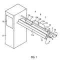
- Fig. 1 and 5 the device according to the invention for the orderly storage of sausage portions from a filling machine 2 is shown in a schematic manner. Under sausage portions 1 one understands here either single sausages or sausage chains with a certain number of individual sausages.
- the term "filling machine” 2 comprises the entire sausage-producing unit, consisting of vacuum filler 5, 6, 4, twisting unit (not shown) and length unit 7, which serves here as a transport device of the filling machine.
- the vacuum filler as shown in Fig. 5, has, as is known, a hopper 5, for filling pasty filling material, such as sausage meat, on, as well as a conveyor, for.
- a vane pump for conveying the contents in a filling tube 4, which are filled in a known manner sausage casings with pasty filling material and then subdivided, for example, by displacement in individual sausages and optionally also be turned off by a twisting device.
- the individual sausages thus produced can then be cut via a separating unit 3 into individual pieces of sausage.
- the individual sausage portions can, as I said, include single sausages or sausage chains with a certain number of sausages.
- the contiguous sausages are divided into individual sausages 1.
- the length unit comprises two circulating conveyor belts, which hold the stuffed sausages and transport in the transport direction T at a first speed V 1 .
- the separation unit 3 is shown integrated within the unit length 7. However, the separation unit 3 can also be arranged after or in front of the transport device 7, ie the length unit 7.
- the sausage portions coming from the filling machine 2 are picked up by the acceleration device 8, in this case the acceleration belt 8, and aligned in the transport direction T.
- the alignment may be effected by a lateral tape guide 9 projecting in lateral areas of the tape 8.
- the acceleration belt 8 moves at least partially faster than the transport device 7 of the filling machine 2
- a gap 20 is created between the individual sausage portions 1.
- either the acceleration belt can move faster than the transport device 7 or the acceleration belt 8 can move when a sausage portion 1 resp at the transition of a separation point of two sausage portions 1 briefly run faster than the transport device 7 of the filling machine, so that the individual sausage portions 1 are pulled apart, so that the gap 20 is formed.
- the length of the gap is dependent on the speed difference between the transport device 7 and the acceleration belt 8 and is for example 20 mm.
- the acceleration device 8 or the acceleration belt 8 can be driven by the motor M1 shown in FIG. 5, which can be adjusted as required in terms of rotational speed and in its dynamic behavior. It is also conceivable to regulate the transport speed, a Staurollband with temporarily braked from below roles.
- the accelerator 8 is not limited in its maximum length. The minimum length corresponds to the length of a sausage portion plus the length of the gap.
- the device according to the invention comprises a sensor C4, which is arranged in the front region of the acceleration device 8 and detects a faulty sausage or sausage chain, so that it can be separated out by a discharge device (air or motor drive).
- a further sensor may be provided (not shown).
- the transition region or the separation point can also be determined by the adjustment of the functions of the unit length unit by the controller 6.
- the gap is achieved by regulating the speed of the accelerator, but the gaps may have been formed prior to takeover.
- the transfer device 12 is provided behind the accelerator device 8, which can push the individual sausage portions 1 laterally from the accelerator device 8.
- the transfer device a transfer rotary valve 12.
- the transfer rotary valve 12 has the task to transfer the individual sausage portions in a magazine 10, or alternatively, equal to a conveyor belt 16 or a corresponding container, etc. (not shown).
- the variable transfer rotary valve 12 comprises in this embodiment three driver plates 14a, 14b, 14c.
- the three driver plates 14 serve to push three sausage portions 1 arranged on the acceleration belt 8 one after the other from the belt 8 one after the other.
- the number n of the driver plates 14 corresponds to the number of sausage portions n, which are to be successively transferred in a row.
- the driver plates 14 are provided in this embodiment with baffles 15a, b, c, wherein the baffles 15 a, b, c each extend substantially perpendicular to the transport direction T of the sausage portions 1, so that the promoted sausage portions 1 can bounce against the baffles 15 ,
- the driver and baffle plates 14, 15 are mounted on a shaft 13, here a polygonal shaft, the transfer rotary valve 12 removably attached here.
- the assembly depends on the grouping task and is made flexible by simply changing the number of baffles or the driver plates 14 and the length of the driver plates.
- the length of a driver plate preferably corresponds at least to the length of a sausage portion.
- the driver plates and the baffles 14, 15 are distributed in the transport direction successively uniformly over the circumference of the shaft 13.
- Fig. 2 shows the driver plates 14, wherein the baffles 15 are not shown. This means that the driver plates 14 are arranged at an angle ⁇ of 120 ° to each other. With a larger number of sausage portions n the driver plates 14 would then be arranged at an angle ⁇ of 360 ° / n to each other. Such an arrangement ensures that, for example, a first driver plate 14a after a full rotation of the shaft 13 is back in the starting position.
- sensors B1 to Bn are located in the region of the respective driver plates 14 and detect whether a sausage portion is present in the area of the driver plates.
- sensors sensor types of any kind can be used, which are suitable to detect the presence of a sausage portion. These may be, for example: optical, mechanical, capacitive, image processing or ultrasonic sensors.
- the number of sensors B depends on the number n of sausage portions n, which are successively pushed by the acceleration belt 8 and are to be transferred into a row.
- the device comprises a magazine 10, here a drum magazine 10, which is shown in more detail in FIGS. 1 and 3.
- the drum magazine 10 has the task, the sausage portions 1, which were brought with the transfer rotary valve 12 at a distance and in a defined position in the transport direction, and continue to pass, for example, to another conveyor belt 16, as shown in Fig. 5 or but in appropriate bowls, etc., to give.
- the drum magazine has a plurality of longitudinal grooves 11A, B, C, D, which serve to receive the sausage portions 1.
- the longitudinal groove 11A can be seen on the front, while the longitudinal groove 11C the acceleration belt 8 faces such that the laterally pushed by the transfer rotary valve 12 from the acceleration belt 8 sausage portion 1 falls into the longitudinal groove 11 B and are held securely by this can.
- the drum magazine 10 is rotatably disposed about its longitudinal axis and can by rotation the recorded sausage portion. 1 carry on.
- the drum magazine 10 can be driven by a servo drive or a similar step-by-step drive M3.
- the device is, as can be seen from Fig. 1, arranged on a housing 17 which contains a control for the acceleration device 8 and the transfer device 12 and the magazine 10. Further, the housing includes a display 19 and an input unit for inputting corresponding parameters.
- conveyor belt 16 with or without Gruppierkassetten as buffer or removal belt conveyor belt 16 with grids for smoking or drying equipment, conveyor belt with individual trays for receiving the sausages.
- the conveyor belt is driven here in individual cycles until a predetermined group number (number of rows in a group) is reached. Upon reaching this desired number of sausage portions per group, the conveyor performs a group trip.
- a wire mesh conveyor belt can be arranged as an inlet of fry-frying cooking lines below the drum magazine 10. Further, a wire mesh conveyor belt can be provided as an inlet of cooling-freezing. In this case, the conveyor belt continuously takes over the sausages from the drum magazine 10.
- the transfer rotary valve 12 shows a preferred embodiment of the transfer rotary valve 12.
- the transfer rotary valve 12 for example, four driver plates 14 a - d, wherein the number of driver plates is not limited to four.
- the individual driver plates 14 are constructed in several parts from a plurality of driver plate segments 114, 214, 314.
- the in the transport direction Mit videplattensegment 114 arranged at the rearmost point has a corresponding baffle plate 15 a.
- the further segments 214, 314 have no baffle plate.
- the Mit psychologyplattensegment 114 which includes a baffle plate 15 a, for example, 5 cm long, while the Mit videplattensegmente 214, 314 without baffle plate are shorter than the segment 114 and, for example, have a length of 4 cm.
- the acceleration belt 8 By the acceleration belt 8, the sausage portions, in Fig. 5, the single sausage 1, taken over by the filling machine 2, transported in a row and aligned by the lateral tape guide 9 in the direction of the acceleration belt. Since here the acceleration belt 8 at least partially faster than the transport device 7 of the filling machine 2, which has produced the sausage portion, results in between the individual sausage portions 1 and at the separation points of the sausage portions a gap 20.
- the transfer rotary valve 12 are as previously described, in their position adjustable sensors B1, B2, B3 detect the presence of a sausage portion. The position of the sensors B1, B2, B3 is set in such a way that the sensors B1, B2 and B3 are located in the region (A, B, C) of the corresponding driver plates 14.
- the first sausage portion 1 passes over the acceleration belt 8 and reaches the baffle plate 15A (position A), it is stopped by the baffle plate 15A and brought into an exact first position.
- the acceleration belt 8 is first briefly decelerated, and then the transfer rotary valve 12 rotates by one pitch, in this case by 120 °, for example, so that the sausage portion can be pushed onto the drum magazine 10 by the driver plate 15A.
- the driver plate 14B or the baffle plate 15B is then in position at position B in order to bring a further subsequent sausage portion through the baffle plate 15B in position.
- the second sensor B2 When the second sensor B2 responds, it rotates Transfer rotary valve 12 again by a pitch and pushes the second sausage portion of the acceleration belt 8, after which then at the point C, the third driver and baffle plate 14C, 15C is in position. This process is repeated until the desired number of sausage portions to be transferred in a row have been removed from the conveyor belt. That is, when the nth incoming sausage position 1 is slid off the belt at a position ahead of the n-1 th place in the transport direction of the accelerator 8, the first follower plate 14A is again in the home position.
- the number of sensors Bn depends on the number of sausage portions n, which are to be successively transferred to the drum magazine 10.
- the drum magazine 10 rotates by one pitch and the sausage portions deposited thereon are transferred to, for example, the subsequent conveyor belt 16.
- the pitch of the drum magazine 10 depends on the number of longitudinal grooves 11. In the four longitudinal grooves as shown in Fig. 3 then moves the drum magazine 10 by 90 °. (1 division ⁇ 360 ° / number of longitudinal grooves).
- the drum magazine 10 a series with n Wurstportionen, here with 3 Wurstportionen pass.
- the further conveyor 16 can continue to move around a sausage width.
- the conveyor belt 16 may continue to stand still and only move further when several rows have been passed from the drum magazine 10.
- the conveyor belt 16 may be equipped with cassettes, which are designed in size to the projected group number (number of rows with each n sausage portions). Alternatively, depending on the application, it may also be a smooth conveyor belt.
- the conveyor belt 16 is moved further by one sausage width.
- the conveyor belt 16 is advanced to the beginning of the next group.
- the conveyor belt 16 is moved until, for example, a laterally mounted proximity switch detects the bridge (alternatively, link chain conveyors can be used with gear drive).
- a laterally mounted proximity switch detects the bridge (alternatively, link chain conveyors can be used with gear drive).
- link chain conveyors can be used with gear drive.
- smooth conveyor belts without cassettes
- a predetermined distance is covered.
- the sausages or sausage chains are transferred to a grid or trays.
- a manual removal of sausage groups from the conveyor belt 16 is conceivable to spare the operator person the counting of the portions during the removal.
- a particular group has a predetermined number of rows.
- the provision of trays or containers on the conveyor belt is also possible.
- Several rows of n sausage portions each in n trays or containers are transferred from the drum magazine 10 before the trays or containers are transported away.
- the drum magazine 10 rotates so often until the desired number of sausage portions are received in the corresponding containers.
- the containers are arranged below the drum magazine 10 such that the individual sausage portions can each be transferred to the tray or the container. If, for example, ten sausages are to be transferred into three containers in the exemplary embodiment shown in FIG. 1, the shaft 13 would have to rotate a total of ten times, so that the driver plates 14a, b, c can each push a sausage portion 1 from the acceleration belt 8 ten times. Also, the drum magazine 10 would have to turn a total of ten times by one division, so that a group number of ten is achieved in the individual containers.
- the functions of the acceleration device 8, the transfer device 12 and the drum magazine are coordinated by the controller 17.
Landscapes
- Life Sciences & Earth Sciences (AREA)
- Engineering & Computer Science (AREA)
- Wood Science & Technology (AREA)
- Zoology (AREA)
- Food Science & Technology (AREA)
- Processing Of Meat And Fish (AREA)
- Meat, Egg Or Seafood Products (AREA)
- Container Filling Or Packaging Operations (AREA)
- Specific Conveyance Elements (AREA)
Priority Applications (8)
| Application Number | Priority Date | Filing Date | Title |
|---|---|---|---|
| DE502005001310T DE502005001310D1 (de) | 2005-04-11 | 2005-04-11 | Vorrichtung und Verfahren zum geordneten Ablegen von getrennten Wurstportionen |
| ES05007894T ES2290811T3 (es) | 2005-04-11 | 2005-04-11 | Dispositivo y procedimiento para la deposicion ordenada de porciones de salchichas independientes. |
| EP05007894A EP1712135B1 (de) | 2005-04-11 | 2005-04-11 | Vorrichtung und Verfahren zum geordneten Ablegen von getrennten Wurstportionen |
| AT05007894T ATE370662T1 (de) | 2005-04-11 | 2005-04-11 | Vorrichtung und verfahren zum geordneten ablegen von getrennten wurstportionen |
| US11/400,415 US7258604B2 (en) | 2005-04-11 | 2006-04-07 | Device and method for the ordered deposition of parted sausage portions |
| JP2006107473A JP4264441B2 (ja) | 2005-04-11 | 2006-04-10 | 分断したソーセージ部分を整然と載置する装置及び方法 |
| RU2006111608/13A RU2323577C2 (ru) | 2005-04-11 | 2006-04-11 | Способ упорядоченного расположения разделенных порций сосисок и устройство для его осуществления |
| CN2006100725124A CN1846509B (zh) | 2005-04-11 | 2006-04-11 | 用于分割后的香肠段的有序存放的装置及方法 |
Applications Claiming Priority (1)
| Application Number | Priority Date | Filing Date | Title |
|---|---|---|---|
| EP05007894A EP1712135B1 (de) | 2005-04-11 | 2005-04-11 | Vorrichtung und Verfahren zum geordneten Ablegen von getrennten Wurstportionen |
Publications (2)
| Publication Number | Publication Date |
|---|---|
| EP1712135A1 EP1712135A1 (de) | 2006-10-18 |
| EP1712135B1 true EP1712135B1 (de) | 2007-08-22 |
Family
ID=34934986
Family Applications (1)
| Application Number | Title | Priority Date | Filing Date |
|---|---|---|---|
| EP05007894A Active EP1712135B1 (de) | 2005-04-11 | 2005-04-11 | Vorrichtung und Verfahren zum geordneten Ablegen von getrennten Wurstportionen |
Country Status (8)
| Country | Link |
|---|---|
| US (1) | US7258604B2 (es) |
| EP (1) | EP1712135B1 (es) |
| JP (1) | JP4264441B2 (es) |
| CN (1) | CN1846509B (es) |
| AT (1) | ATE370662T1 (es) |
| DE (1) | DE502005001310D1 (es) |
| ES (1) | ES2290811T3 (es) |
| RU (1) | RU2323577C2 (es) |
Cited By (1)
| Publication number | Priority date | Publication date | Assignee | Title |
|---|---|---|---|---|
| EP3162739A1 (de) | 2015-10-26 | 2017-05-03 | Albert Handtmann Maschinenfabrik GmbH & Co. KG | Vorrichtung und verfahren zum übergeben von wurstportionen |
Families Citing this family (17)
| Publication number | Priority date | Publication date | Assignee | Title |
|---|---|---|---|---|
| US7128920B2 (en) * | 2001-12-17 | 2006-10-31 | Replidyne, Inc. | metRS2 |
| DE202004007789U1 (de) * | 2004-05-12 | 2005-10-06 | Tipper Tie Technopack Gmbh | Vorrichtung zum automatisierten Überwachen von Verpackungsmaschinen für die Wurstherstellung |
| US7563158B2 (en) * | 2005-07-01 | 2009-07-21 | Poly-Clip System Corp. | Automatic rack loader |
| NL2002580C2 (en) * | 2009-02-27 | 2010-08-30 | Meijn Food Proc Technology B V | Deskinner for poultry parts. |
| DE102009033725A1 (de) * | 2009-07-17 | 2011-03-24 | Vemag Maschinenbau Gmbh | Verfahren und Vorrichtung zum Herstellen von Würstchen |
| CH701502B1 (de) * | 2009-07-24 | 2013-06-28 | Tipper Tie Alpina Ag | Vorrichtung zum Aufhängen von Würsten. |
| JP5736160B2 (ja) * | 2010-12-02 | 2015-06-17 | プリマハム株式会社 | 食品移送装置 |
| EP2572585B1 (en) * | 2011-09-26 | 2016-08-24 | Poly-clip System GmbH & Co. KG | Transportation device with star wheels |
| EP2609809B1 (en) * | 2011-12-27 | 2018-04-18 | Poly-clip System GmbH & Co. KG | Transfer device with split conveyor means |
| US9382025B2 (en) * | 2014-06-30 | 2016-07-05 | Marel Meat Processing Inc. | Conveying system for transporting, transferring and staging food products |
| US9463888B2 (en) * | 2014-06-30 | 2016-10-11 | The Procter & Gamble Company | Packaging equipment for rolled paper products |
| EP3025587B1 (de) | 2014-11-26 | 2017-09-13 | Albert Handtmann Maschinenfabrik GmbH & Co. KG | Vorrichtung und Verfahren zur Übergabe von Wurstportionen |
| EP3180989B1 (de) * | 2015-12-16 | 2020-02-05 | Albert Handtmann Maschinenfabrik GmbH & Co. KG | Verfahren und vorrichtung zum herstellen von lebensmittelprodukten, insbesondere von hüllenlosen produkten einer bestimmten form |
| CN107352079B (zh) * | 2017-08-08 | 2023-04-25 | 郑州润华智能设备有限公司 | 一种多支肠用机器人摆肠机 |
| DE202017104924U1 (de) * | 2017-08-16 | 2017-09-06 | Vemag Maschinenbau Gmbh | Vorrichtung zum Ausrichten von Würsten |
| CN114056658A (zh) * | 2021-11-29 | 2022-02-18 | 江西欧丽仕智能科技有限公司 | 一种香肠包装线用转运机构 |
| CN114847327B (zh) * | 2022-04-25 | 2022-12-13 | 永康市凯亚工贸有限公司 | 一种充分利用原料的快退式香肠机 |
Family Cites Families (10)
| Publication number | Priority date | Publication date | Assignee | Title |
|---|---|---|---|---|
| GB1517511A (en) * | 1974-07-19 | 1978-07-12 | Metal Box Co Ltd | Conveyor handling apparatus |
| US4261456A (en) * | 1979-06-27 | 1981-04-14 | R. A. Jones & Co. Inc. | Method and apparatus for transferring tubes into cartoner product buckets |
| FR2525436A1 (fr) * | 1982-04-26 | 1983-10-28 | Lassoudry Philippe Ets | Procede de fabrication de produits, notamment alimentaires, tels que par exemple des saucissons ou analogues, et installation pour la mise en oeuvre de ce procede |
| DE3545673C2 (de) * | 1985-12-21 | 1995-12-21 | Schnell Maschfab Karl | Portioniermaschine |
| DE4410391C2 (de) * | 1994-03-25 | 1996-08-08 | Atmos Anlagenbau Gmbh | Beladeeinrichtung zum automatischen Beladen kontinuierlich arbeitender Durchlaufanlagen mit Wurststrängen |
| ITMI20020089A1 (it) * | 2002-01-18 | 2003-07-18 | Refin Srl | Apparecchiatura per il posizionamento automatico in vaschetta di singoli pezzi cilindrici in particolare salsicce o altri prodotti alimentar |
| US7048622B2 (en) * | 2002-02-04 | 2006-05-23 | Conagra Foods, Inc. | Automated laterally offset retractable food dislodgement or guiding mechanisms and associated methods and systems |
| EP1348345B1 (de) * | 2002-03-28 | 2006-09-13 | Sander Hansen A/S | Vorrichtung zum Pasteurisieren |
| US6645062B1 (en) * | 2002-08-29 | 2003-11-11 | Hormel Foods, Llc | Method and apparatus for stuffing hams |
| US6845860B1 (en) * | 2004-02-20 | 2005-01-25 | Arr Tech, Inc. | Conveyor transfer apparatus |
-
2005
- 2005-04-11 AT AT05007894T patent/ATE370662T1/de active
- 2005-04-11 ES ES05007894T patent/ES2290811T3/es active Active
- 2005-04-11 EP EP05007894A patent/EP1712135B1/de active Active
- 2005-04-11 DE DE502005001310T patent/DE502005001310D1/de active Active
-
2006
- 2006-04-07 US US11/400,415 patent/US7258604B2/en active Active
- 2006-04-10 JP JP2006107473A patent/JP4264441B2/ja active Active
- 2006-04-11 RU RU2006111608/13A patent/RU2323577C2/ru active
- 2006-04-11 CN CN2006100725124A patent/CN1846509B/zh active Active
Non-Patent Citations (1)
| Title |
|---|
| None * |
Cited By (2)
| Publication number | Priority date | Publication date | Assignee | Title |
|---|---|---|---|---|
| EP3162739A1 (de) | 2015-10-26 | 2017-05-03 | Albert Handtmann Maschinenfabrik GmbH & Co. KG | Vorrichtung und verfahren zum übergeben von wurstportionen |
| US10820600B2 (en) | 2015-10-26 | 2020-11-03 | Albert Handtmann Maschinenfabrik Gmbh & Co. Kg | Device and method for transferring sausage portions |
Also Published As
| Publication number | Publication date |
|---|---|
| CN1846509A (zh) | 2006-10-18 |
| DE502005001310D1 (de) | 2007-10-04 |
| ES2290811T3 (es) | 2008-02-16 |
| JP4264441B2 (ja) | 2009-05-20 |
| CN1846509B (zh) | 2010-05-12 |
| RU2323577C2 (ru) | 2008-05-10 |
| ATE370662T1 (de) | 2007-09-15 |
| US20060240754A1 (en) | 2006-10-26 |
| JP2006288397A (ja) | 2006-10-26 |
| US7258604B2 (en) | 2007-08-21 |
| EP1712135A1 (de) | 2006-10-18 |
| RU2006111608A (ru) | 2007-10-20 |
Similar Documents
| Publication | Publication Date | Title |
|---|---|---|
| EP1712135B1 (de) | Vorrichtung und Verfahren zum geordneten Ablegen von getrennten Wurstportionen | |
| EP2836447B1 (de) | Vorrichtung und verfahren zum fördern von stückigen produkten | |
| EP3153025B1 (de) | Vorrichtung zum behandeln einzelner würste | |
| EP3400805B1 (de) | Vorrichtung und verfahren zum übergeben und einlegen von würstchengruppen in eine verpackung | |
| EP1955604B1 (de) | Vorrichtung und Verfahren zum Befüllen von Behältern mit stabförmigen Produkten | |
| DE2903461C2 (es) | ||
| DE102007021146A1 (de) | Vorrichtung und Verfahren zum Handhaben von flachen Gegenständen, insbesondere Windeln | |
| EP3162739B1 (de) | Vorrichtung und verfahren zum übergeben von wurstportionen | |
| DE102011084018A1 (de) | Verfahren und Vorrichtung zum Fördern von streifenförmigen oder plattenförmigen Produkten | |
| DE2732898C2 (de) | Vorrichtung zum Zusammensetzen von stabförmigen Gegenständen | |
| DE1285931B (de) | Zwischenfoerderer fuer nebeneinanderliegende Reihen von Filterstaeben, Zigaretten oder anderen stabfoermigen Gegenstaenden | |
| EP2008522A1 (de) | Verfahren und Vorrichtung zum Aufnehmen von Portionen mit Schlaufe | |
| EP1854359B1 (de) | Mittel zur Verknüpfung einer zentralen Zuführungseinrichtung mit einer Verarbeitungsmaschine sowie eine Anlage und ein Verfahren zur automatisierten Verarbeitung von Fisch | |
| EP3449730B1 (de) | Vorrichtung zum abteilen von schlauchförmigen hüllen | |
| DE3114102A1 (de) | Verfahren und vorrichtung zum zufuehren von boegen au papier, pappe o.dgl. | |
| EP3160878B1 (de) | Verfahren und vorrichtung zum fördern von stückigen produkten | |
| DE102013219847A1 (de) | Vorrichtung und Verfahren zum Umgang mit Artikeln | |
| EP3613293B1 (de) | Wurstbehandlungsvorrichtung und -verfahren | |
| EP4000829A1 (de) | Verfahren zum positionieren eines zu transportierenden artikels sowie vorrichtung zur durchführung des verfahrens | |
| EP2653044A2 (de) | Einrichtung zur Zusammenstellung von Filtersegmentgruppen | |
| EP3539910B1 (de) | Förderbandsystem zum bilden einer vorbestimmten anordnung von produkten | |
| EP3025587B1 (de) | Vorrichtung und Verfahren zur Übergabe von Wurstportionen | |
| EP1579932A1 (de) | Vorrichtung zum Abbremsen und Auswerfen von stabförmigem Material | |
| DE3616542A1 (de) | Verfahren und vorrichtung zum zufuehren stabfoermiger gegenstaende der tabakverarbeitenden industrie | |
| EP3972921A1 (de) | Verfahren, computerprogramm und vorrichtung zum aufreihen von portionen von lebensmittelscheiben |
Legal Events
| Date | Code | Title | Description |
|---|---|---|---|
| PUAI | Public reference made under article 153(3) epc to a published international application that has entered the european phase |
Free format text: ORIGINAL CODE: 0009012 |
|
| 17P | Request for examination filed |
Effective date: 20051007 |
|
| AK | Designated contracting states |
Kind code of ref document: A1 Designated state(s): AT BE BG CH CY CZ DE DK EE ES FI FR GB GR HU IE IS IT LI LT LU MC NL PL PT RO SE SI SK TR |
|
| AX | Request for extension of the european patent |
Extension state: AL BA HR LV MK YU |
|
| GRAP | Despatch of communication of intention to grant a patent |
Free format text: ORIGINAL CODE: EPIDOSNIGR1 |
|
| GRAS | Grant fee paid |
Free format text: ORIGINAL CODE: EPIDOSNIGR3 |
|
| AKX | Designation fees paid |
Designated state(s): AT BE BG CH CY CZ DE DK EE ES FI FR GB GR HU IE IS IT LI LT LU MC NL PL PT RO SE SI SK TR |
|
| GRAA | (expected) grant |
Free format text: ORIGINAL CODE: 0009210 |
|
| AK | Designated contracting states |
Kind code of ref document: B1 Designated state(s): AT BE BG CH CY CZ DE DK EE ES FI FR GB GR HU IE IS IT LI LT LU MC NL PL PT RO SE SI SK TR |
|
| REG | Reference to a national code |
Ref country code: GB Ref legal event code: FG4D Free format text: NOT ENGLISH |
|
| GBT | Gb: translation of ep patent filed (gb section 77(6)(a)/1977) |
Effective date: 20070822 |
|
| REG | Reference to a national code |
Ref country code: CH Ref legal event code: EP |
|
| REG | Reference to a national code |
Ref country code: IE Ref legal event code: FG4D Free format text: LANGUAGE OF EP DOCUMENT: GERMAN |
|
| REF | Corresponds to: |
Ref document number: 502005001310 Country of ref document: DE Date of ref document: 20071004 Kind code of ref document: P |
|
| PG25 | Lapsed in a contracting state [announced via postgrant information from national office to epo] |
Ref country code: LT Free format text: LAPSE BECAUSE OF FAILURE TO SUBMIT A TRANSLATION OF THE DESCRIPTION OR TO PAY THE FEE WITHIN THE PRESCRIBED TIME-LIMIT Effective date: 20070822 Ref country code: BG Free format text: LAPSE BECAUSE OF FAILURE TO SUBMIT A TRANSLATION OF THE DESCRIPTION OR TO PAY THE FEE WITHIN THE PRESCRIBED TIME-LIMIT Effective date: 20071122 Ref country code: IS Free format text: LAPSE BECAUSE OF FAILURE TO SUBMIT A TRANSLATION OF THE DESCRIPTION OR TO PAY THE FEE WITHIN THE PRESCRIBED TIME-LIMIT Effective date: 20071222 Ref country code: FI Free format text: LAPSE BECAUSE OF FAILURE TO SUBMIT A TRANSLATION OF THE DESCRIPTION OR TO PAY THE FEE WITHIN THE PRESCRIBED TIME-LIMIT Effective date: 20070822 |
|
| REG | Reference to a national code |
Ref country code: ES Ref legal event code: FG2A Ref document number: 2290811 Country of ref document: ES Kind code of ref document: T3 |
|
| PG25 | Lapsed in a contracting state [announced via postgrant information from national office to epo] |
Ref country code: PL Free format text: LAPSE BECAUSE OF FAILURE TO SUBMIT A TRANSLATION OF THE DESCRIPTION OR TO PAY THE FEE WITHIN THE PRESCRIBED TIME-LIMIT Effective date: 20070822 |
|
| ET | Fr: translation filed | ||
| REG | Reference to a national code |
Ref country code: IE Ref legal event code: FD4D |
|
| PG25 | Lapsed in a contracting state [announced via postgrant information from national office to epo] |
Ref country code: GR Free format text: LAPSE BECAUSE OF FAILURE TO SUBMIT A TRANSLATION OF THE DESCRIPTION OR TO PAY THE FEE WITHIN THE PRESCRIBED TIME-LIMIT Effective date: 20071123 Ref country code: DK Free format text: LAPSE BECAUSE OF FAILURE TO SUBMIT A TRANSLATION OF THE DESCRIPTION OR TO PAY THE FEE WITHIN THE PRESCRIBED TIME-LIMIT Effective date: 20070822 |
|
| PG25 | Lapsed in a contracting state [announced via postgrant information from national office to epo] |
Ref country code: PT Free format text: LAPSE BECAUSE OF FAILURE TO SUBMIT A TRANSLATION OF THE DESCRIPTION OR TO PAY THE FEE WITHIN THE PRESCRIBED TIME-LIMIT Effective date: 20080122 Ref country code: IE Free format text: LAPSE BECAUSE OF FAILURE TO SUBMIT A TRANSLATION OF THE DESCRIPTION OR TO PAY THE FEE WITHIN THE PRESCRIBED TIME-LIMIT Effective date: 20070822 Ref country code: CZ Free format text: LAPSE BECAUSE OF FAILURE TO SUBMIT A TRANSLATION OF THE DESCRIPTION OR TO PAY THE FEE WITHIN THE PRESCRIBED TIME-LIMIT Effective date: 20070822 Ref country code: SK Free format text: LAPSE BECAUSE OF FAILURE TO SUBMIT A TRANSLATION OF THE DESCRIPTION OR TO PAY THE FEE WITHIN THE PRESCRIBED TIME-LIMIT Effective date: 20070822 |
|
| PLBI | Opposition filed |
Free format text: ORIGINAL CODE: 0009260 |
|
| PG25 | Lapsed in a contracting state [announced via postgrant information from national office to epo] |
Ref country code: RO Free format text: LAPSE BECAUSE OF FAILURE TO SUBMIT A TRANSLATION OF THE DESCRIPTION OR TO PAY THE FEE WITHIN THE PRESCRIBED TIME-LIMIT Effective date: 20070822 Ref country code: SE Free format text: LAPSE BECAUSE OF FAILURE TO SUBMIT A TRANSLATION OF THE DESCRIPTION OR TO PAY THE FEE WITHIN THE PRESCRIBED TIME-LIMIT Effective date: 20071122 |
|
| 26 | Opposition filed |
Opponent name: VEMAG MASCHINENBAU GMBH Effective date: 20080522 Opponent name: STORK TOWNSEND B.V. Effective date: 20080522 |
|
| NLR1 | Nl: opposition has been filed with the epo |
Opponent name: VEMAG MASCHINENBAU GMBH Opponent name: STORK TOWNSEND B.V. |
|
| PLAX | Notice of opposition and request to file observation + time limit sent |
Free format text: ORIGINAL CODE: EPIDOSNOBS2 |
|
| PLBB | Reply of patent proprietor to notice(s) of opposition received |
Free format text: ORIGINAL CODE: EPIDOSNOBS3 |
|
| BERE | Be: lapsed |
Owner name: ALBERT HANDTMANN MASCHINENFABRIK G.M.B.H. & CO. KG Effective date: 20080430 |
|
| PG25 | Lapsed in a contracting state [announced via postgrant information from national office to epo] |
Ref country code: MC Free format text: LAPSE BECAUSE OF NON-PAYMENT OF DUE FEES Effective date: 20080430 |
|
| PG25 | Lapsed in a contracting state [announced via postgrant information from national office to epo] |
Ref country code: EE Free format text: LAPSE BECAUSE OF FAILURE TO SUBMIT A TRANSLATION OF THE DESCRIPTION OR TO PAY THE FEE WITHIN THE PRESCRIBED TIME-LIMIT Effective date: 20070822 |
|
| PG25 | Lapsed in a contracting state [announced via postgrant information from national office to epo] |
Ref country code: BE Free format text: LAPSE BECAUSE OF NON-PAYMENT OF DUE FEES Effective date: 20080430 |
|
| PLAY | Examination report in opposition despatched + time limit |
Free format text: ORIGINAL CODE: EPIDOSNORE2 |
|
| PG25 | Lapsed in a contracting state [announced via postgrant information from national office to epo] |
Ref country code: SI Free format text: LAPSE BECAUSE OF FAILURE TO SUBMIT A TRANSLATION OF THE DESCRIPTION OR TO PAY THE FEE WITHIN THE PRESCRIBED TIME-LIMIT Effective date: 20070822 |
|
| PG25 | Lapsed in a contracting state [announced via postgrant information from national office to epo] |
Ref country code: CY Free format text: LAPSE BECAUSE OF FAILURE TO SUBMIT A TRANSLATION OF THE DESCRIPTION OR TO PAY THE FEE WITHIN THE PRESCRIBED TIME-LIMIT Effective date: 20070822 |
|
| PLAH | Information related to despatch of examination report in opposition + time limit modified |
Free format text: ORIGINAL CODE: EPIDOSCORE2 |
|
| REG | Reference to a national code |
Ref country code: CH Ref legal event code: PL |
|
| PLAH | Information related to despatch of examination report in opposition + time limit modified |
Free format text: ORIGINAL CODE: EPIDOSCORE2 |
|
| PG25 | Lapsed in a contracting state [announced via postgrant information from national office to epo] |
Ref country code: LI Free format text: LAPSE BECAUSE OF NON-PAYMENT OF DUE FEES Effective date: 20090430 Ref country code: CH Free format text: LAPSE BECAUSE OF NON-PAYMENT OF DUE FEES Effective date: 20090430 |
|
| PLBC | Reply to examination report in opposition received |
Free format text: ORIGINAL CODE: EPIDOSNORE3 |
|
| PG25 | Lapsed in a contracting state [announced via postgrant information from national office to epo] |
Ref country code: LU Free format text: LAPSE BECAUSE OF NON-PAYMENT OF DUE FEES Effective date: 20080411 Ref country code: HU Free format text: LAPSE BECAUSE OF FAILURE TO SUBMIT A TRANSLATION OF THE DESCRIPTION OR TO PAY THE FEE WITHIN THE PRESCRIBED TIME-LIMIT Effective date: 20080223 |
|
| PG25 | Lapsed in a contracting state [announced via postgrant information from national office to epo] |
Ref country code: TR Free format text: LAPSE BECAUSE OF FAILURE TO SUBMIT A TRANSLATION OF THE DESCRIPTION OR TO PAY THE FEE WITHIN THE PRESCRIBED TIME-LIMIT Effective date: 20070822 |
|
| PLAB | Opposition data, opponent's data or that of the opponent's representative modified |
Free format text: ORIGINAL CODE: 0009299OPPO |
|
| R26 | Opposition filed (corrected) |
Opponent name: STORK TOWNSEND B.V. Effective date: 20080522 Opponent name: VEMAG MASCHINENBAU GMBH Effective date: 20080522 |
|
| PLBP | Opposition withdrawn |
Free format text: ORIGINAL CODE: 0009264 |
|
| PLCK | Communication despatched that opposition was rejected |
Free format text: ORIGINAL CODE: EPIDOSNREJ1 |
|
| APBM | Appeal reference recorded |
Free format text: ORIGINAL CODE: EPIDOSNREFNO |
|
| APBP | Date of receipt of notice of appeal recorded |
Free format text: ORIGINAL CODE: EPIDOSNNOA2O |
|
| APAH | Appeal reference modified |
Free format text: ORIGINAL CODE: EPIDOSCREFNO |
|
| APBQ | Date of receipt of statement of grounds of appeal recorded |
Free format text: ORIGINAL CODE: EPIDOSNNOA3O |
|
| REG | Reference to a national code |
Ref country code: DE Ref legal event code: R100 Ref document number: 502005001310 Country of ref document: DE |
|
| APBU | Appeal procedure closed |
Free format text: ORIGINAL CODE: EPIDOSNNOA9O |
|
| PLBN | Opposition rejected |
Free format text: ORIGINAL CODE: 0009273 |
|
| STAA | Information on the status of an ep patent application or granted ep patent |
Free format text: STATUS: OPPOSITION REJECTED |
|
| 27O | Opposition rejected |
Effective date: 20140905 |
|
| REG | Reference to a national code |
Ref country code: DE Ref legal event code: R100 Ref document number: 502005001310 Country of ref document: DE Effective date: 20140905 |
|
| REG | Reference to a national code |
Ref country code: FR Ref legal event code: PLFP Year of fee payment: 12 |
|
| REG | Reference to a national code |
Ref country code: FR Ref legal event code: PLFP Year of fee payment: 13 |
|
| REG | Reference to a national code |
Ref country code: FR Ref legal event code: PLFP Year of fee payment: 14 |
|
| P01 | Opt-out of the competence of the unified patent court (upc) registered |
Effective date: 20230523 |
|
| PGFP | Annual fee paid to national office [announced via postgrant information from national office to epo] |
Ref country code: NL Payment date: 20230422 Year of fee payment: 19 |
|
| PGFP | Annual fee paid to national office [announced via postgrant information from national office to epo] |
Ref country code: IT Payment date: 20230428 Year of fee payment: 19 Ref country code: FR Payment date: 20230425 Year of fee payment: 19 Ref country code: ES Payment date: 20230503 Year of fee payment: 19 Ref country code: DE Payment date: 20230425 Year of fee payment: 19 |
|
| PGFP | Annual fee paid to national office [announced via postgrant information from national office to epo] |
Ref country code: AT Payment date: 20230426 Year of fee payment: 19 |
|
| PGFP | Annual fee paid to national office [announced via postgrant information from national office to epo] |
Ref country code: GB Payment date: 20230420 Year of fee payment: 19 |