EP1710488A2 - Einheit bestehend aus einem Beleuchtungsmast und einer relativen Vorrichtung für die Montage wenigstens eines Lichtkörpers - Google Patents
Einheit bestehend aus einem Beleuchtungsmast und einer relativen Vorrichtung für die Montage wenigstens eines Lichtkörpers Download PDFInfo
- Publication number
- EP1710488A2 EP1710488A2 EP06111443A EP06111443A EP1710488A2 EP 1710488 A2 EP1710488 A2 EP 1710488A2 EP 06111443 A EP06111443 A EP 06111443A EP 06111443 A EP06111443 A EP 06111443A EP 1710488 A2 EP1710488 A2 EP 1710488A2
- Authority
- EP
- European Patent Office
- Prior art keywords
- pole
- unit according
- tubular element
- lighting
- assembly
- Prior art date
- Legal status (The legal status is an assumption and is not a legal conclusion. Google has not performed a legal analysis and makes no representation as to the accuracy of the status listed.)
- Withdrawn
Links
Images


Classifications
-
- F—MECHANICAL ENGINEERING; LIGHTING; HEATING; WEAPONS; BLASTING
- F21—LIGHTING
- F21S—NON-PORTABLE LIGHTING DEVICES; SYSTEMS THEREOF; VEHICLE LIGHTING DEVICES SPECIALLY ADAPTED FOR VEHICLE EXTERIORS
- F21S8/00—Lighting devices intended for fixed installation
- F21S8/08—Lighting devices intended for fixed installation with a standard
- F21S8/081—Lighting devices intended for fixed installation with a standard of low-built type, e.g. landscape light
-
- F—MECHANICAL ENGINEERING; LIGHTING; HEATING; WEAPONS; BLASTING
- F21—LIGHTING
- F21V—FUNCTIONAL FEATURES OR DETAILS OF LIGHTING DEVICES OR SYSTEMS THEREOF; STRUCTURAL COMBINATIONS OF LIGHTING DEVICES WITH OTHER ARTICLES, NOT OTHERWISE PROVIDED FOR
- F21V21/00—Supporting, suspending, or attaching arrangements for lighting devices; Hand grips
- F21V21/10—Pendants, arms, or standards; Fixing lighting devices to pendants, arms, or standards
- F21V21/116—Fixing lighting devices to arms or standards
-
- F—MECHANICAL ENGINEERING; LIGHTING; HEATING; WEAPONS; BLASTING
- F21—LIGHTING
- F21V—FUNCTIONAL FEATURES OR DETAILS OF LIGHTING DEVICES OR SYSTEMS THEREOF; STRUCTURAL COMBINATIONS OF LIGHTING DEVICES WITH OTHER ARTICLES, NOT OTHERWISE PROVIDED FOR
- F21V21/00—Supporting, suspending, or attaching arrangements for lighting devices; Hand grips
- F21V21/10—Pendants, arms, or standards; Fixing lighting devices to pendants, arms, or standards
Definitions
- the present invention relates to a unit consisting of a pole for lighting appliances and a relative device for the assembly of at least one lighting body.
- Lighting appliances in particular, for street lighting or for external environments are generally applied close to an upper end of a pole which, in addition to supporting the lighting appliances, houses and seals electric wires.
- An objective of the present invention is to provide a unit consisting of a pole for lighting appliances and a relative device for the assembly of at least one lighting body comprising a reduced number of elements which can be easily assembled.
- a further objective of the present invention is to provide a visibly screwless sealed unit.
- Another objective of the present invention is to provide a unit consisting of a pole for lighting appliances and a relative device for the assembly of at least one lighting body which is particularly simple and functional, with limited costs.
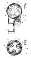
- these show a unit, indicated as a whole with 10, consisting of a pole 11 for lighting appliances and a relative device for the assembly 12 of one or more lighting bodies 13 on the top of the pole 11.
- Figures 1 to 5 show how the device 12, used for the assembly of a lighting body 13, comprises a tubular element 14 substantially having the same section of the pole 11, which is shown in the figures for illustrative but non-limiting purposes with a circular section.
- the lighting body is then connected to the assembly device 12 by means of an articulation, for example with a joint 15, or rigidly.
- the tubular element 14 and the pole 11 respectively comprise facing coupling surfaces 16 and 17, equipped with complementary constraining means 18 with a vertical axis, for example of the threaded type.
- the tubular element 14, which is internally hollow, is applied in a removable manner to the top of the pole 11 by means of the constraining means which are accessible from the inside through an upper opening which can be closed as a sealing by a cover 19.
- a first surface 16, arranged close to the top of the pole 11, is equipped with threaded holes, i.e. at least one threaded hole, for coupling with the same number of threaded stems.
- the constraining means 18, for example screws, are housed in pass-through seats 20 situated on a second coupling surface 17 positioned close to a lower end of the tubular element 14.
- the constraining means 18, which in the embodiment shown are equal to three, are distributed along the perimeter of the complementary coupling surfaces, for example equidistant from each other.
- Figures 3 and 5 also show a perforated flange 21 positioned on the upper surface of the pass-through seats 20 for the buffer positioning of the heads of the screws 18.
- the first coupling surface 16 is situated at a lower height with respect to the top of the pole 11.
- the tubular element 14 does in fact have a lower centering portion 22 with a reduced diameter which is inserted into the top of the pole 11 to produce the contact between the coupling surfaces 16 and 17 in the internal area of the pole 11.
- the first coupling surface 16 for example a plate welded to an inner surface of the pole, equipped with threaded holes in addition to at least one opening for the passage of wires.
- the first coupling surface 16 consists of a series of protuberances 23 with a flat upper surface which extend from the inner wall of the pole 11 towards its inside in correspondence with the screws 18, and in which each of the protuberances 23 is equipped with a threaded hole.
- the device for the assembly of an illuminating body also comprises an arm 28 extending outwards in a substantially orthogonal direction with respect to the tubular element 14 for the jointed constraint with the illuminating body 13. Said arm 28, however, can extend outwards in any other direction considered suitable.
- the arm 28, which can be produced in a single piece with the tubular element 14, or removably joined to the same with screws 24, has a joint 15 at a free end for orientating the lighting body 13, which can be of any type known to experts in the field.
- tubular element 14 and the arm 28 are also equipped with holes 25 for the passage of wires.
- Figure 6 shows how the assembly device allows, according to the same innovative concept, three arms 28 to be assembled, arranged at 120° from each other with respect to the axis of the pole 11.
- the number of arms and their positioning can differ each time in relation to the specific demands.
- the application of the single lighting body 13 to the upper end of the pole 11 is effected, after passing the wire, not shown, leaving the pole through the assembly device 12, by resting it on the top of the pole 11 with the coupling surfaces 16 and 17 in contact with each other.
- the assembly device By tightening the screws 18 from inside the tubular element 14 and positioning the lid 19, the assembly device is firmly applied to the top of the pole 11. It is therefore possible to join the lighting body 13 to the arm 28 of the assembly device 12 and terminate its wiring.
- the unit consisting of a pole for lighting appliances and a relative device for the assembly of at least one lighting body, object of the present invention, has the advantage of being able to be easily assembled.
- the unit advantageously envisages an aligned positioning of the elements thus reducing discontinuity on the outer surface of the product.
- the constraining means to the pole are advantageously protected with respect to the outside environment thus reducing possible infiltrations of water and humidity inside the pole itself.
Landscapes
- Engineering & Computer Science (AREA)
- General Engineering & Computer Science (AREA)
- Non-Portable Lighting Devices Or Systems Thereof (AREA)
- Fastening Of Light Sources Or Lamp Holders (AREA)
Applications Claiming Priority (1)
| Application Number | Priority Date | Filing Date | Title |
|---|---|---|---|
| ITMI20050123 ITMI20050123U1 (it) | 2005-04-08 | 2005-04-08 | Assieme costituito da un palo per apparecchi di illuminazione e da un relativo dispositivo per il montaggio di almeno un corpo illuminante |
Publications (2)
| Publication Number | Publication Date |
|---|---|
| EP1710488A2 true EP1710488A2 (de) | 2006-10-11 |
| EP1710488A3 EP1710488A3 (de) | 2007-05-09 |
Family
ID=36579648
Family Applications (1)
| Application Number | Title | Priority Date | Filing Date |
|---|---|---|---|
| EP06111443A Withdrawn EP1710488A3 (de) | 2005-04-08 | 2006-03-21 | Einheit bestehend aus einem Beleuchtungsmast und einer relativen Vorrichtung für die Montage wenigstens eines Lichtkörpers |
Country Status (4)
| Country | Link |
|---|---|
| EP (1) | EP1710488A3 (de) |
| CN (1) | CN1877192A (de) |
| IT (1) | ITMI20050123U1 (de) |
| NO (1) | NO20061496L (de) |
Families Citing this family (2)
| Publication number | Priority date | Publication date | Assignee | Title |
|---|---|---|---|---|
| CN101900307B (zh) * | 2010-06-29 | 2013-03-27 | 海洋王照明科技股份有限公司 | 灯具的立柱式安装装置 |
| CN103335287B (zh) * | 2013-06-14 | 2015-09-09 | 广州市胜亚灯具制造有限公司 | 一种悬臂灯的连接机构 |
Citations (4)
| Publication number | Priority date | Publication date | Assignee | Title |
|---|---|---|---|---|
| FR2188789A7 (de) * | 1972-06-15 | 1974-01-18 | Semperlux Gmbh | |
| US4143413A (en) * | 1975-10-10 | 1979-03-06 | Kelly James P | Luminaire mounting arrangement |
| DE3812668A1 (de) * | 1988-04-15 | 1989-10-26 | Siemens Ag | Mastaufsatzleuchte |
| US5266738A (en) * | 1991-10-25 | 1993-11-30 | United Lighting Standards, Inc. | Universal fixture mount and method of assembly |
-
2005
- 2005-04-08 IT ITMI20050123 patent/ITMI20050123U1/it unknown
-
2006
- 2006-03-21 EP EP06111443A patent/EP1710488A3/de not_active Withdrawn
- 2006-04-03 NO NO20061496A patent/NO20061496L/no not_active Application Discontinuation
- 2006-04-07 CN CNA2006100733135A patent/CN1877192A/zh active Pending
Patent Citations (4)
| Publication number | Priority date | Publication date | Assignee | Title |
|---|---|---|---|---|
| FR2188789A7 (de) * | 1972-06-15 | 1974-01-18 | Semperlux Gmbh | |
| US4143413A (en) * | 1975-10-10 | 1979-03-06 | Kelly James P | Luminaire mounting arrangement |
| DE3812668A1 (de) * | 1988-04-15 | 1989-10-26 | Siemens Ag | Mastaufsatzleuchte |
| US5266738A (en) * | 1991-10-25 | 1993-11-30 | United Lighting Standards, Inc. | Universal fixture mount and method of assembly |
Also Published As
| Publication number | Publication date |
|---|---|
| ITMI20050123U1 (it) | 2006-10-09 |
| EP1710488A3 (de) | 2007-05-09 |
| NO20061496L (no) | 2006-10-09 |
| CN1877192A (zh) | 2006-12-13 |
Similar Documents
| Publication | Publication Date | Title |
|---|---|---|
| EP1710488A2 (de) | Einheit bestehend aus einem Beleuchtungsmast und einer relativen Vorrichtung für die Montage wenigstens eines Lichtkörpers | |
| JP2008020132A (ja) | 空気調和機の室外機 | |
| US20060248972A1 (en) | Installation structure of oil inclusion device and control unit thereof | |
| JP4805727B2 (ja) | ヘッダー用保温部材、およびヘッダー用保温部材の取付方法 | |
| ES2282942T3 (es) | Dispositivo de conexion para la conexion hermetizada de los conductores de un cable a un modulo electronico alojado en una carcasa. | |
| RU2578670C2 (ru) | Стенная вставка | |
| JP2018046631A (ja) | 電線管接続構造及び屋外用電気機器 | |
| CN209202790U (zh) | 一种烹饪器具 | |
| ATE403963T1 (de) | Elektrodose mit ring | |
| FR2732826A1 (fr) | Boitier pour appareillage electrique | |
| KR200251403Y1 (ko) | 와이어 하네스 고정용 클립 | |
| JP6609531B2 (ja) | 埋設式ガス栓の取付構造 | |
| JPH1014682A (ja) | 流し台 | |
| KR102710923B1 (ko) | 통합형 스위치 | |
| CN219438849U (zh) | 一种防水结构、把手结构及烹饪装置 | |
| JP4436691B2 (ja) | 閉塞カバー | |
| KR200252128Y1 (ko) | 김치저장고의 힌지구조 | |
| KR200404679Y1 (ko) | 보일러 하이드로블록의 워터라인 연결부 조립구조 | |
| JP3125835U (ja) | レバーハンドル | |
| JP3763671B2 (ja) | エアコン用冷媒管の保護カバー装置 | |
| KR200262945Y1 (ko) | 계량기함의 접속단자대 | |
| JP2526546Y2 (ja) | 表示灯 | |
| KR950010456Y1 (ko) | 자외선 살균 식기 건조기용 프리도어 | |
| JP2004250996A (ja) | 浴槽の遠隔操作排水栓装置 | |
| JPH0736284B2 (ja) | 照明器具 |
Legal Events
| Date | Code | Title | Description |
|---|---|---|---|
| PUAI | Public reference made under article 153(3) epc to a published international application that has entered the european phase |
Free format text: ORIGINAL CODE: 0009012 |
|
| AK | Designated contracting states |
Kind code of ref document: A2 Designated state(s): AT BE BG CH CY CZ DE DK EE ES FI FR GB GR HU IE IS IT LI LT LU LV MC NL PL PT RO SE SI SK TR |
|
| AX | Request for extension of the european patent |
Extension state: AL BA HR MK YU |
|
| PUAL | Search report despatched |
Free format text: ORIGINAL CODE: 0009013 |
|
| AK | Designated contracting states |
Kind code of ref document: A3 Designated state(s): AT BE BG CH CY CZ DE DK EE ES FI FR GB GR HU IE IS IT LI LT LU LV MC NL PL PT RO SE SI SK TR |
|
| AX | Request for extension of the european patent |
Extension state: AL BA HR MK YU |
|
| 17P | Request for examination filed |
Effective date: 20070726 |
|
| 17Q | First examination report despatched |
Effective date: 20070823 |
|
| AKX | Designation fees paid |
Designated state(s): AT BE BG CH CY CZ DE DK EE ES FI FR GB GR HU IE IS IT LI LT LU LV MC NL PL PT RO SE SI SK TR |
|
| STAA | Information on the status of an ep patent application or granted ep patent |
Free format text: STATUS: THE APPLICATION IS DEEMED TO BE WITHDRAWN |
|
| 18D | Application deemed to be withdrawn |
Effective date: 20080103 |