EP1710488A2 - Unit consisting of a pole for lighting appliances and a relative device for the assembly of at least one lighting body - Google Patents
Unit consisting of a pole for lighting appliances and a relative device for the assembly of at least one lighting body Download PDFInfo
- Publication number
- EP1710488A2 EP1710488A2 EP06111443A EP06111443A EP1710488A2 EP 1710488 A2 EP1710488 A2 EP 1710488A2 EP 06111443 A EP06111443 A EP 06111443A EP 06111443 A EP06111443 A EP 06111443A EP 1710488 A2 EP1710488 A2 EP 1710488A2
- Authority
- EP
- European Patent Office
- Prior art keywords
- pole
- unit according
- tubular element
- lighting
- assembly
- Prior art date
- Legal status (The legal status is an assumption and is not a legal conclusion. Google has not performed a legal analysis and makes no representation as to the accuracy of the status listed.)
- Withdrawn
Links
Images


Classifications
-
- F—MECHANICAL ENGINEERING; LIGHTING; HEATING; WEAPONS; BLASTING
- F21—LIGHTING
- F21S—NON-PORTABLE LIGHTING DEVICES; SYSTEMS THEREOF; VEHICLE LIGHTING DEVICES SPECIALLY ADAPTED FOR VEHICLE EXTERIORS
- F21S8/00—Lighting devices intended for fixed installation
- F21S8/08—Lighting devices intended for fixed installation with a standard
- F21S8/081—Lighting devices intended for fixed installation with a standard of low-built type, e.g. landscape light
-
- F—MECHANICAL ENGINEERING; LIGHTING; HEATING; WEAPONS; BLASTING
- F21—LIGHTING
- F21V—FUNCTIONAL FEATURES OR DETAILS OF LIGHTING DEVICES OR SYSTEMS THEREOF; STRUCTURAL COMBINATIONS OF LIGHTING DEVICES WITH OTHER ARTICLES, NOT OTHERWISE PROVIDED FOR
- F21V21/00—Supporting, suspending, or attaching arrangements for lighting devices; Hand grips
- F21V21/10—Pendants, arms, or standards; Fixing lighting devices to pendants, arms, or standards
- F21V21/116—Fixing lighting devices to arms or standards
-
- F—MECHANICAL ENGINEERING; LIGHTING; HEATING; WEAPONS; BLASTING
- F21—LIGHTING
- F21V—FUNCTIONAL FEATURES OR DETAILS OF LIGHTING DEVICES OR SYSTEMS THEREOF; STRUCTURAL COMBINATIONS OF LIGHTING DEVICES WITH OTHER ARTICLES, NOT OTHERWISE PROVIDED FOR
- F21V21/00—Supporting, suspending, or attaching arrangements for lighting devices; Hand grips
- F21V21/10—Pendants, arms, or standards; Fixing lighting devices to pendants, arms, or standards
Abstract
Description
- The present invention relates to a unit consisting of a pole for lighting appliances and a relative device for the assembly of at least one lighting body.
- Lighting appliances, in particular, for street lighting or for external environments are generally applied close to an upper end of a pole which, in addition to supporting the lighting appliances, houses and seals electric wires.
- An objective of the present invention is to provide a unit consisting of a pole for lighting appliances and a relative device for the assembly of at least one lighting body comprising a reduced number of elements which can be easily assembled.
- A further objective of the present invention is to provide a visibly screwless sealed unit.
- Another objective of the present invention is to provide a unit consisting of a pole for lighting appliances and a relative device for the assembly of at least one lighting body which is particularly simple and functional, with limited costs.
- These objectives according to the present invention are achieved by providing a unit consisting of a pole for lighting appliances and a relative device for the assembly of at least one lighting body as specified in claim 1.
- Further characteristics of a unit are object of the dependent claims.
- The characteristics and advantages of a unit consisting of a pole for lighting appliances and a relative device for the assembly of at least one lighting body according to the present invention will appear more evident from the following illustrative and non-limiting description, referring to the enclosed drawings in which:
- figure 1 is a perspective view of a lighting appliance comprising a pole and a lighting body connected thereto;
- figure 2 is a raised view of a unit consisting of a pole for lighting appliances and a relative device for the assembly of a lighting body according to the present invention;
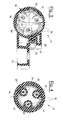
- figures 3 to 5 are sectional views of the unit of figure 2 indicated respectively according to the traces III-III, IV-IV and V-V;
- figure 6 shows a further embodiment of the invention wherein the device for the assembly allows the assembly of three lighting bodies.
- With reference to the figures, these show a unit, indicated as a whole with 10, consisting of a
pole 11 for lighting appliances and a relative device for theassembly 12 of one ormore lighting bodies 13 on the top of thepole 11. - Figures 1 to 5 show how the
device 12, used for the assembly of alighting body 13, comprises atubular element 14 substantially having the same section of thepole 11, which is shown in the figures for illustrative but non-limiting purposes with a circular section. - The lighting body is then connected to the
assembly device 12 by means of an articulation, for example with ajoint 15, or rigidly. - The
tubular element 14 and thepole 11 respectively comprise facingcoupling surfaces tubular element 14, which is internally hollow, is applied in a removable manner to the top of thepole 11 by means of the constraining means which are accessible from the inside through an upper opening which can be closed as a sealing by acover 19. - A
first surface 16, arranged close to the top of thepole 11, is equipped with threaded holes, i.e. at least one threaded hole, for coupling with the same number of threaded stems. - The constraining means 18, for example screws, are housed in pass-through
seats 20 situated on asecond coupling surface 17 positioned close to a lower end of thetubular element 14. - The constraining means 18, which in the embodiment shown are equal to three, are distributed along the perimeter of the complementary coupling surfaces, for example equidistant from each other.
- Figures 3 and 5 also show a
perforated flange 21 positioned on the upper surface of the pass-throughseats 20 for the buffer positioning of the heads of thescrews 18. - For a greater centering stability, the
first coupling surface 16 is situated at a lower height with respect to the top of thepole 11. Thetubular element 14 does in fact have alower centering portion 22 with a reduced diameter which is inserted into the top of thepole 11 to produce the contact between thecoupling surfaces pole 11. - The
first coupling surface 16, for example a plate welded to an inner surface of the pole, equipped with threaded holes in addition to at least one opening for the passage of wires. - The
first coupling surface 16, according to a preferred embodiment shown in the figures, consists of a series ofprotuberances 23 with a flat upper surface which extend from the inner wall of thepole 11 towards its inside in correspondence with thescrews 18, and in which each of theprotuberances 23 is equipped with a threaded hole. - The device for the assembly of an illuminating body also comprises an
arm 28 extending outwards in a substantially orthogonal direction with respect to thetubular element 14 for the jointed constraint with theilluminating body 13. Saidarm 28, however, can extend outwards in any other direction considered suitable. - The
arm 28, which can be produced in a single piece with thetubular element 14, or removably joined to the same withscrews 24, has ajoint 15 at a free end for orientating thelighting body 13, which can be of any type known to experts in the field. - As shown in figures 3 to 5, according to a preferred embodiment, the
tubular element 14 and thearm 28 are also equipped withholes 25 for the passage of wires. - Figure 6 shows how the assembly device allows, according to the same innovative concept, three
arms 28 to be assembled, arranged at 120° from each other with respect to the axis of thepole 11. In this case, there is either the integral formation of said number of arms or the presence of adequate removable fixing elements (screws 24). The number of arms and their positioning can differ each time in relation to the specific demands. - The application of the
single lighting body 13 to the upper end of thepole 11 is effected, after passing the wire, not shown, leaving the pole through theassembly device 12, by resting it on the top of thepole 11 with thecoupling surfaces - By tightening the
screws 18 from inside thetubular element 14 and positioning thelid 19, the assembly device is firmly applied to the top of thepole 11. It is therefore possible to join thelighting body 13 to thearm 28 of theassembly device 12 and terminate its wiring. - The unit consisting of a pole for lighting appliances and a relative device for the assembly of at least one lighting body, object of the present invention, has the advantage of being able to be easily assembled.
- The unit advantageously envisages an aligned positioning of the elements thus reducing discontinuity on the outer surface of the product.
- Furthermore, in the unit, object of the present invention, the constraining means to the pole are advantageously protected with respect to the outside environment thus reducing possible infiltrations of water and humidity inside the pole itself.
Claims (14)
- A unit consisting of a pole (11) for lighting appliances and a relative device for the assembly (12) of at least one lighting body (13), comprising a tubular element (14) substantially having the same section of the pole (11), characterized in that said tubular element (14) and said pole (11) respectively comprise facing coupling surfaces (16, 17) equipped with complementary constraining means (18) with a vertical axis, said assembly device (12) being openable above by the tightening of said constraining means (18).
- The unit according to claim 1, characterized in that said constraining means (18) comprise at least one threaded hole on a first of said coupling surfaces (16) situated close to the top of said pole (11), and at least one threaded stem housed in at least one pass-through seat (20) produced on a second of said coupling surfaces (17) situated close to a lower end of said tubular element (14).
- The unit according to claim 2, characterized in that said first coupling surface (16) is situated at a lower height with respect to the top of said pole (11).
- The unit according to claim 3, characterized in that said tubular element (14) comprises at the lower end, a lower centering portion (22) with a reduced diameter for the insertion of said pole (11) into the top.
- The unit according to claim 2, characterized in that said constraining means (18) are distributed along the perimeter of said complementary coupling surfaces (16, 17).
- The unit according to claim 2, characterized in that said device for the assembly (12) of at least one lighting body comprises a perforated flange (21) situated on the upper surface of said pass-through seats (20) for the buffer positioning of the constraining means (18).
- The unit according to claim 1, characterized in that said first coupling surface (16) is a plate joined to an inner surface of said pole, said plate being equipped with at least one opening for the passage of wires.
- The unit according to claim 7, characterized in that said first coupling surface (16) consists of a series of protuberances (23) which extend from the internal wall of the pole (11), each of said protuberances (23) having constraining means (18).
- The unit according to claim 1, characterized in that said tubular element (14) can be closed above as a seal by means of a cover (19).
- The unit according to claim 1, characterized in that said assembly device (12) comprises at least one arm (28) for constraint to the lighting body (13) extending outwards with respect to said tubular element (14).
- The unit according to claim 10, characterized in that said at least one arm (28) extends outwards in a substantially orthogonal direction.
- The unit according to claim 10 or 11, characterized in that said at least one arm (28) is removably joined by means of screws (24) to said tubular element (14).
- The unit according to claim 10 or 11, characterized in that said at least one arm (28) comprises at a free end a joint (15) for the orientation of said lighting body (13).
- The unit according to claim 10 or 11, characterized in that said tubular element (14) and said at least one arm (28) are equipped with holes (25) for the passage of wires.
Applications Claiming Priority (1)
| Application Number | Priority Date | Filing Date | Title |
|---|---|---|---|
| ITMI20050123 ITMI20050123U1 (en) | 2005-04-08 | 2005-04-08 | ASSEMBLED BY A POLE FOR LIGHTING EQUIPMENT AND A RELATIVE DEVICE FOR THE ASSEMBLY OF AT LEAST ONE ILLUMINATING BODY |
Publications (2)
| Publication Number | Publication Date |
|---|---|
| EP1710488A2 true EP1710488A2 (en) | 2006-10-11 |
| EP1710488A3 EP1710488A3 (en) | 2007-05-09 |
Family
ID=36579648
Family Applications (1)
| Application Number | Title | Priority Date | Filing Date |
|---|---|---|---|
| EP06111443A Withdrawn EP1710488A3 (en) | 2005-04-08 | 2006-03-21 | Unit consisting of a pole for lighting appliances and a relative device for the assembly of at least one lighting body |
Country Status (4)
| Country | Link |
|---|---|
| EP (1) | EP1710488A3 (en) |
| CN (1) | CN1877192A (en) |
| IT (1) | ITMI20050123U1 (en) |
| NO (1) | NO20061496L (en) |
Families Citing this family (2)
| Publication number | Priority date | Publication date | Assignee | Title |
|---|---|---|---|---|
| CN101900307B (en) * | 2010-06-29 | 2013-03-27 | 海洋王照明科技股份有限公司 | Column installation device for lamp |
| CN103335287B (en) * | 2013-06-14 | 2015-09-09 | 广州市胜亚灯具制造有限公司 | A kind of bindiny mechanism of cantilever lamp |
Citations (4)
| Publication number | Priority date | Publication date | Assignee | Title |
|---|---|---|---|---|
| FR2188789A7 (en) * | 1972-06-15 | 1974-01-18 | Semperlux Gmbh | |
| US4143413A (en) * | 1975-10-10 | 1979-03-06 | Kelly James P | Luminaire mounting arrangement |
| DE3812668A1 (en) * | 1988-04-15 | 1989-10-26 | Siemens Ag | Post-top luminaire |
| US5266738A (en) * | 1991-10-25 | 1993-11-30 | United Lighting Standards, Inc. | Universal fixture mount and method of assembly |
-
2005
- 2005-04-08 IT ITMI20050123 patent/ITMI20050123U1/en unknown
-
2006
- 2006-03-21 EP EP06111443A patent/EP1710488A3/en not_active Withdrawn
- 2006-04-03 NO NO20061496A patent/NO20061496L/en not_active Application Discontinuation
- 2006-04-07 CN CNA2006100733135A patent/CN1877192A/en active Pending
Patent Citations (4)
| Publication number | Priority date | Publication date | Assignee | Title |
|---|---|---|---|---|
| FR2188789A7 (en) * | 1972-06-15 | 1974-01-18 | Semperlux Gmbh | |
| US4143413A (en) * | 1975-10-10 | 1979-03-06 | Kelly James P | Luminaire mounting arrangement |
| DE3812668A1 (en) * | 1988-04-15 | 1989-10-26 | Siemens Ag | Post-top luminaire |
| US5266738A (en) * | 1991-10-25 | 1993-11-30 | United Lighting Standards, Inc. | Universal fixture mount and method of assembly |
Also Published As
| Publication number | Publication date |
|---|---|
| EP1710488A3 (en) | 2007-05-09 |
| NO20061496L (en) | 2006-10-09 |
| ITMI20050123U1 (en) | 2006-10-09 |
| CN1877192A (en) | 2006-12-13 |
Similar Documents
| Publication | Publication Date | Title |
|---|---|---|
| EP1710488A2 (en) | Unit consisting of a pole for lighting appliances and a relative device for the assembly of at least one lighting body | |
| JP2008020132A (en) | Outdoor unit for air conditioner | |
| JP2008231773A (en) | Composite sash | |
| US20060248972A1 (en) | Installation structure of oil inclusion device and control unit thereof | |
| JP4805727B2 (en) | Heat insulation member for header and mounting method of heat insulation member for header | |
| ES2282942T3 (en) | CONNECTION DEVICE FOR THE HERMETIZED CONNECTION OF THE CONDUCTORS OF A CABLE TO AN ELECTRONIC MODULE ACCOMMODATED IN A HOUSING. | |
| KR200251403Y1 (en) | Clip For Fixing The Wire Harness | |
| RU2578670C2 (en) | Wall insert | |
| JP2018046631A (en) | Conduit connecting structure and outdoor electric device | |
| CN209202790U (en) | Cooking utensil | |
| ATE403963T1 (en) | ELECTRICAL SOCKET WITH RING | |
| FR2732826A1 (en) | HOUSING FOR ELECTRICAL EQUIPMENT | |
| KR200388559Y1 (en) | A Connecting Device of Wall | |
| JP2002322703A (en) | Drain plug device of bathtub | |
| KR200416246Y1 (en) | Cable Closure | |
| KR200321659Y1 (en) | Assembly structure of prefabricated panel | |
| CN219438849U (en) | Waterproof construction, handle structure and cooking device | |
| JP4436691B2 (en) | Obstruction cover | |
| KR200404679Y1 (en) | Assembling structure for water line connecting part at the hydro block of boiler | |
| JP3125835U (en) | Lever handle | |
| JP2526546Y2 (en) | Indicator light | |
| KR950010456Y1 (en) | The free-door for ultra-violet rays-sterilizer | |
| JP6609531B2 (en) | Mounting structure of buried gas plug | |
| JP3740870B2 (en) | Silent device for equipment using relay | |
| JP2004250996A (en) | Remote-operated drain valve device for bathtub |
Legal Events
| Date | Code | Title | Description |
|---|---|---|---|
| PUAI | Public reference made under article 153(3) epc to a published international application that has entered the european phase |
Free format text: ORIGINAL CODE: 0009012 |
|
| AK | Designated contracting states |
Kind code of ref document: A2 Designated state(s): AT BE BG CH CY CZ DE DK EE ES FI FR GB GR HU IE IS IT LI LT LU LV MC NL PL PT RO SE SI SK TR |
|
| AX | Request for extension of the european patent |
Extension state: AL BA HR MK YU |
|
| PUAL | Search report despatched |
Free format text: ORIGINAL CODE: 0009013 |
|
| AK | Designated contracting states |
Kind code of ref document: A3 Designated state(s): AT BE BG CH CY CZ DE DK EE ES FI FR GB GR HU IE IS IT LI LT LU LV MC NL PL PT RO SE SI SK TR |
|
| AX | Request for extension of the european patent |
Extension state: AL BA HR MK YU |
|
| 17P | Request for examination filed |
Effective date: 20070726 |
|
| 17Q | First examination report despatched |
Effective date: 20070823 |
|
| AKX | Designation fees paid |
Designated state(s): AT BE BG CH CY CZ DE DK EE ES FI FR GB GR HU IE IS IT LI LT LU LV MC NL PL PT RO SE SI SK TR |
|
| STAA | Information on the status of an ep patent application or granted ep patent |
Free format text: STATUS: THE APPLICATION IS DEEMED TO BE WITHDRAWN |
|
| 18D | Application deemed to be withdrawn |
Effective date: 20080103 |