EP1710445A2 - Hydraulische Steuerung - Google Patents
Hydraulische Steuerung Download PDFInfo
- Publication number
- EP1710445A2 EP1710445A2 EP05027271A EP05027271A EP1710445A2 EP 1710445 A2 EP1710445 A2 EP 1710445A2 EP 05027271 A EP05027271 A EP 05027271A EP 05027271 A EP05027271 A EP 05027271A EP 1710445 A2 EP1710445 A2 EP 1710445A2
- Authority
- EP
- European Patent Office
- Prior art keywords
- pressure
- valve
- control
- working
- load
- Prior art date
- Legal status (The legal status is an assumption and is not a legal conclusion. Google has not performed a legal analysis and makes no representation as to the accuracy of the status listed.)
- Withdrawn
Links
Images


Classifications
-
- F—MECHANICAL ENGINEERING; LIGHTING; HEATING; WEAPONS; BLASTING
- F15—FLUID-PRESSURE ACTUATORS; HYDRAULICS OR PNEUMATICS IN GENERAL
- F15B—SYSTEMS ACTING BY MEANS OF FLUIDS IN GENERAL; FLUID-PRESSURE ACTUATORS, e.g. SERVOMOTORS; DETAILS OF FLUID-PRESSURE SYSTEMS, NOT OTHERWISE PROVIDED FOR
- F15B11/00—Servomotor systems without provision for follow-up action; Circuits therefor
- F15B11/02—Systems essentially incorporating special features for controlling the speed or actuating force of an output member
- F15B11/04—Systems essentially incorporating special features for controlling the speed or actuating force of an output member for controlling the speed
- F15B11/044—Systems essentially incorporating special features for controlling the speed or actuating force of an output member for controlling the speed by means in the return line, i.e. "meter out"
- F15B11/0445—Systems essentially incorporating special features for controlling the speed or actuating force of an output member for controlling the speed by means in the return line, i.e. "meter out" with counterbalance valves, e.g. to prevent overrunning or for braking
-
- F—MECHANICAL ENGINEERING; LIGHTING; HEATING; WEAPONS; BLASTING
- F15—FLUID-PRESSURE ACTUATORS; HYDRAULICS OR PNEUMATICS IN GENERAL
- F15B—SYSTEMS ACTING BY MEANS OF FLUIDS IN GENERAL; FLUID-PRESSURE ACTUATORS, e.g. SERVOMOTORS; DETAILS OF FLUID-PRESSURE SYSTEMS, NOT OTHERWISE PROVIDED FOR
- F15B21/00—Common features of fluid actuator systems; Fluid-pressure actuator systems or details thereof, not covered by any other group of this subclass
-
- F—MECHANICAL ENGINEERING; LIGHTING; HEATING; WEAPONS; BLASTING
- F15—FLUID-PRESSURE ACTUATORS; HYDRAULICS OR PNEUMATICS IN GENERAL
- F15B—SYSTEMS ACTING BY MEANS OF FLUIDS IN GENERAL; FLUID-PRESSURE ACTUATORS, e.g. SERVOMOTORS; DETAILS OF FLUID-PRESSURE SYSTEMS, NOT OTHERWISE PROVIDED FOR
- F15B11/00—Servomotor systems without provision for follow-up action; Circuits therefor
- F15B11/02—Systems essentially incorporating special features for controlling the speed or actuating force of an output member
- F15B11/04—Systems essentially incorporating special features for controlling the speed or actuating force of an output member for controlling the speed
- F15B11/05—Systems essentially incorporating special features for controlling the speed or actuating force of an output member for controlling the speed specially adapted to maintain constant speed, e.g. pressure-compensated, load-responsive
-
- F—MECHANICAL ENGINEERING; LIGHTING; HEATING; WEAPONS; BLASTING
- F15—FLUID-PRESSURE ACTUATORS; HYDRAULICS OR PNEUMATICS IN GENERAL
- F15B—SYSTEMS ACTING BY MEANS OF FLUIDS IN GENERAL; FLUID-PRESSURE ACTUATORS, e.g. SERVOMOTORS; DETAILS OF FLUID-PRESSURE SYSTEMS, NOT OTHERWISE PROVIDED FOR
- F15B2211/00—Circuits for servomotor systems
- F15B2211/20—Fluid pressure source, e.g. accumulator or variable axial piston pump
- F15B2211/205—Systems with pumps
- F15B2211/2053—Type of pump
- F15B2211/20546—Type of pump variable capacity
- F15B2211/20553—Type of pump variable capacity with pilot circuit, e.g. for controlling a swash plate
-
- F—MECHANICAL ENGINEERING; LIGHTING; HEATING; WEAPONS; BLASTING
- F15—FLUID-PRESSURE ACTUATORS; HYDRAULICS OR PNEUMATICS IN GENERAL
- F15B—SYSTEMS ACTING BY MEANS OF FLUIDS IN GENERAL; FLUID-PRESSURE ACTUATORS, e.g. SERVOMOTORS; DETAILS OF FLUID-PRESSURE SYSTEMS, NOT OTHERWISE PROVIDED FOR
- F15B2211/00—Circuits for servomotor systems
- F15B2211/30—Directional control
- F15B2211/305—Directional control characterised by the type of valves
- F15B2211/30525—Directional control valves, e.g. 4/3-directional control valve
- F15B2211/3053—In combination with a pressure compensating valve
- F15B2211/30535—In combination with a pressure compensating valve the pressure compensating valve is arranged between pressure source and directional control valve
-
- F—MECHANICAL ENGINEERING; LIGHTING; HEATING; WEAPONS; BLASTING
- F15—FLUID-PRESSURE ACTUATORS; HYDRAULICS OR PNEUMATICS IN GENERAL
- F15B—SYSTEMS ACTING BY MEANS OF FLUIDS IN GENERAL; FLUID-PRESSURE ACTUATORS, e.g. SERVOMOTORS; DETAILS OF FLUID-PRESSURE SYSTEMS, NOT OTHERWISE PROVIDED FOR
- F15B2211/00—Circuits for servomotor systems
- F15B2211/30—Directional control
- F15B2211/31—Directional control characterised by the positions of the valve element
- F15B2211/3122—Special positions other than the pump port being connected to working ports or the working ports being connected to the return line
- F15B2211/3127—Floating position connecting the working ports and the return line
-
- F—MECHANICAL ENGINEERING; LIGHTING; HEATING; WEAPONS; BLASTING
- F15—FLUID-PRESSURE ACTUATORS; HYDRAULICS OR PNEUMATICS IN GENERAL
- F15B—SYSTEMS ACTING BY MEANS OF FLUIDS IN GENERAL; FLUID-PRESSURE ACTUATORS, e.g. SERVOMOTORS; DETAILS OF FLUID-PRESSURE SYSTEMS, NOT OTHERWISE PROVIDED FOR
- F15B2211/00—Circuits for servomotor systems
- F15B2211/30—Directional control
- F15B2211/32—Directional control characterised by the type of actuation
- F15B2211/329—Directional control characterised by the type of actuation actuated by fluid pressure
-
- F—MECHANICAL ENGINEERING; LIGHTING; HEATING; WEAPONS; BLASTING
- F15—FLUID-PRESSURE ACTUATORS; HYDRAULICS OR PNEUMATICS IN GENERAL
- F15B—SYSTEMS ACTING BY MEANS OF FLUIDS IN GENERAL; FLUID-PRESSURE ACTUATORS, e.g. SERVOMOTORS; DETAILS OF FLUID-PRESSURE SYSTEMS, NOT OTHERWISE PROVIDED FOR
- F15B2211/00—Circuits for servomotor systems
- F15B2211/40—Flow control
- F15B2211/405—Flow control characterised by the type of flow control means or valve
- F15B2211/40515—Flow control characterised by the type of flow control means or valve with variable throttles or orifices
-
- F—MECHANICAL ENGINEERING; LIGHTING; HEATING; WEAPONS; BLASTING
- F15—FLUID-PRESSURE ACTUATORS; HYDRAULICS OR PNEUMATICS IN GENERAL
- F15B—SYSTEMS ACTING BY MEANS OF FLUIDS IN GENERAL; FLUID-PRESSURE ACTUATORS, e.g. SERVOMOTORS; DETAILS OF FLUID-PRESSURE SYSTEMS, NOT OTHERWISE PROVIDED FOR
- F15B2211/00—Circuits for servomotor systems
- F15B2211/40—Flow control
- F15B2211/42—Flow control characterised by the type of actuation
- F15B2211/421—Flow control characterised by the type of actuation mechanically
-
- F—MECHANICAL ENGINEERING; LIGHTING; HEATING; WEAPONS; BLASTING
- F15—FLUID-PRESSURE ACTUATORS; HYDRAULICS OR PNEUMATICS IN GENERAL
- F15B—SYSTEMS ACTING BY MEANS OF FLUIDS IN GENERAL; FLUID-PRESSURE ACTUATORS, e.g. SERVOMOTORS; DETAILS OF FLUID-PRESSURE SYSTEMS, NOT OTHERWISE PROVIDED FOR
- F15B2211/00—Circuits for servomotor systems
- F15B2211/40—Flow control
- F15B2211/42—Flow control characterised by the type of actuation
- F15B2211/428—Flow control characterised by the type of actuation actuated by fluid pressure
-
- F—MECHANICAL ENGINEERING; LIGHTING; HEATING; WEAPONS; BLASTING
- F15—FLUID-PRESSURE ACTUATORS; HYDRAULICS OR PNEUMATICS IN GENERAL
- F15B—SYSTEMS ACTING BY MEANS OF FLUIDS IN GENERAL; FLUID-PRESSURE ACTUATORS, e.g. SERVOMOTORS; DETAILS OF FLUID-PRESSURE SYSTEMS, NOT OTHERWISE PROVIDED FOR
- F15B2211/00—Circuits for servomotor systems
- F15B2211/40—Flow control
- F15B2211/45—Control of bleed-off flow, e.g. control of bypass flow to the return line
-
- F—MECHANICAL ENGINEERING; LIGHTING; HEATING; WEAPONS; BLASTING
- F15—FLUID-PRESSURE ACTUATORS; HYDRAULICS OR PNEUMATICS IN GENERAL
- F15B—SYSTEMS ACTING BY MEANS OF FLUIDS IN GENERAL; FLUID-PRESSURE ACTUATORS, e.g. SERVOMOTORS; DETAILS OF FLUID-PRESSURE SYSTEMS, NOT OTHERWISE PROVIDED FOR
- F15B2211/00—Circuits for servomotor systems
- F15B2211/40—Flow control
- F15B2211/455—Control of flow in the feed line, i.e. meter-in control
-
- F—MECHANICAL ENGINEERING; LIGHTING; HEATING; WEAPONS; BLASTING
- F15—FLUID-PRESSURE ACTUATORS; HYDRAULICS OR PNEUMATICS IN GENERAL
- F15B—SYSTEMS ACTING BY MEANS OF FLUIDS IN GENERAL; FLUID-PRESSURE ACTUATORS, e.g. SERVOMOTORS; DETAILS OF FLUID-PRESSURE SYSTEMS, NOT OTHERWISE PROVIDED FOR
- F15B2211/00—Circuits for servomotor systems
- F15B2211/40—Flow control
- F15B2211/46—Control of flow in the return line, i.e. meter-out control
-
- F—MECHANICAL ENGINEERING; LIGHTING; HEATING; WEAPONS; BLASTING
- F15—FLUID-PRESSURE ACTUATORS; HYDRAULICS OR PNEUMATICS IN GENERAL
- F15B—SYSTEMS ACTING BY MEANS OF FLUIDS IN GENERAL; FLUID-PRESSURE ACTUATORS, e.g. SERVOMOTORS; DETAILS OF FLUID-PRESSURE SYSTEMS, NOT OTHERWISE PROVIDED FOR
- F15B2211/00—Circuits for servomotor systems
- F15B2211/40—Flow control
- F15B2211/47—Flow control in one direction only
- F15B2211/473—Flow control in one direction only without restriction in the reverse direction
-
- F—MECHANICAL ENGINEERING; LIGHTING; HEATING; WEAPONS; BLASTING
- F15—FLUID-PRESSURE ACTUATORS; HYDRAULICS OR PNEUMATICS IN GENERAL
- F15B—SYSTEMS ACTING BY MEANS OF FLUIDS IN GENERAL; FLUID-PRESSURE ACTUATORS, e.g. SERVOMOTORS; DETAILS OF FLUID-PRESSURE SYSTEMS, NOT OTHERWISE PROVIDED FOR
- F15B2211/00—Circuits for servomotor systems
- F15B2211/50—Pressure control
- F15B2211/505—Pressure control characterised by the type of pressure control means
- F15B2211/50509—Pressure control characterised by the type of pressure control means the pressure control means controlling a pressure upstream of the pressure control means
- F15B2211/50518—Pressure control characterised by the type of pressure control means the pressure control means controlling a pressure upstream of the pressure control means using pressure relief valves
-
- F—MECHANICAL ENGINEERING; LIGHTING; HEATING; WEAPONS; BLASTING
- F15—FLUID-PRESSURE ACTUATORS; HYDRAULICS OR PNEUMATICS IN GENERAL
- F15B—SYSTEMS ACTING BY MEANS OF FLUIDS IN GENERAL; FLUID-PRESSURE ACTUATORS, e.g. SERVOMOTORS; DETAILS OF FLUID-PRESSURE SYSTEMS, NOT OTHERWISE PROVIDED FOR
- F15B2211/00—Circuits for servomotor systems
- F15B2211/50—Pressure control
- F15B2211/505—Pressure control characterised by the type of pressure control means
- F15B2211/50509—Pressure control characterised by the type of pressure control means the pressure control means controlling a pressure upstream of the pressure control means
- F15B2211/50545—Pressure control characterised by the type of pressure control means the pressure control means controlling a pressure upstream of the pressure control means using braking valves to maintain a back pressure
-
- F—MECHANICAL ENGINEERING; LIGHTING; HEATING; WEAPONS; BLASTING
- F15—FLUID-PRESSURE ACTUATORS; HYDRAULICS OR PNEUMATICS IN GENERAL
- F15B—SYSTEMS ACTING BY MEANS OF FLUIDS IN GENERAL; FLUID-PRESSURE ACTUATORS, e.g. SERVOMOTORS; DETAILS OF FLUID-PRESSURE SYSTEMS, NOT OTHERWISE PROVIDED FOR
- F15B2211/00—Circuits for servomotor systems
- F15B2211/50—Pressure control
- F15B2211/505—Pressure control characterised by the type of pressure control means
- F15B2211/50563—Pressure control characterised by the type of pressure control means the pressure control means controlling a differential pressure
- F15B2211/50572—Pressure control characterised by the type of pressure control means the pressure control means controlling a differential pressure using a pressure compensating valve for controlling the pressure difference across a flow control valve
-
- F—MECHANICAL ENGINEERING; LIGHTING; HEATING; WEAPONS; BLASTING
- F15—FLUID-PRESSURE ACTUATORS; HYDRAULICS OR PNEUMATICS IN GENERAL
- F15B—SYSTEMS ACTING BY MEANS OF FLUIDS IN GENERAL; FLUID-PRESSURE ACTUATORS, e.g. SERVOMOTORS; DETAILS OF FLUID-PRESSURE SYSTEMS, NOT OTHERWISE PROVIDED FOR
- F15B2211/00—Circuits for servomotor systems
- F15B2211/50—Pressure control
- F15B2211/505—Pressure control characterised by the type of pressure control means
- F15B2211/50563—Pressure control characterised by the type of pressure control means the pressure control means controlling a differential pressure
- F15B2211/50581—Pressure control characterised by the type of pressure control means the pressure control means controlling a differential pressure using counterbalance valves
-
- F—MECHANICAL ENGINEERING; LIGHTING; HEATING; WEAPONS; BLASTING
- F15—FLUID-PRESSURE ACTUATORS; HYDRAULICS OR PNEUMATICS IN GENERAL
- F15B—SYSTEMS ACTING BY MEANS OF FLUIDS IN GENERAL; FLUID-PRESSURE ACTUATORS, e.g. SERVOMOTORS; DETAILS OF FLUID-PRESSURE SYSTEMS, NOT OTHERWISE PROVIDED FOR
- F15B2211/00—Circuits for servomotor systems
- F15B2211/50—Pressure control
- F15B2211/515—Pressure control characterised by the connections of the pressure control means in the circuit
- F15B2211/5153—Pressure control characterised by the connections of the pressure control means in the circuit being connected to an output member and a directional control valve
-
- F—MECHANICAL ENGINEERING; LIGHTING; HEATING; WEAPONS; BLASTING
- F15—FLUID-PRESSURE ACTUATORS; HYDRAULICS OR PNEUMATICS IN GENERAL
- F15B—SYSTEMS ACTING BY MEANS OF FLUIDS IN GENERAL; FLUID-PRESSURE ACTUATORS, e.g. SERVOMOTORS; DETAILS OF FLUID-PRESSURE SYSTEMS, NOT OTHERWISE PROVIDED FOR
- F15B2211/00—Circuits for servomotor systems
- F15B2211/50—Pressure control
- F15B2211/55—Pressure control for limiting a pressure up to a maximum pressure, e.g. by using a pressure relief valve
-
- F—MECHANICAL ENGINEERING; LIGHTING; HEATING; WEAPONS; BLASTING
- F15—FLUID-PRESSURE ACTUATORS; HYDRAULICS OR PNEUMATICS IN GENERAL
- F15B—SYSTEMS ACTING BY MEANS OF FLUIDS IN GENERAL; FLUID-PRESSURE ACTUATORS, e.g. SERVOMOTORS; DETAILS OF FLUID-PRESSURE SYSTEMS, NOT OTHERWISE PROVIDED FOR
- F15B2211/00—Circuits for servomotor systems
- F15B2211/50—Pressure control
- F15B2211/575—Pilot pressure control
-
- F—MECHANICAL ENGINEERING; LIGHTING; HEATING; WEAPONS; BLASTING
- F15—FLUID-PRESSURE ACTUATORS; HYDRAULICS OR PNEUMATICS IN GENERAL
- F15B—SYSTEMS ACTING BY MEANS OF FLUIDS IN GENERAL; FLUID-PRESSURE ACTUATORS, e.g. SERVOMOTORS; DETAILS OF FLUID-PRESSURE SYSTEMS, NOT OTHERWISE PROVIDED FOR
- F15B2211/00—Circuits for servomotor systems
- F15B2211/60—Circuit components or control therefor
- F15B2211/605—Load sensing circuits
- F15B2211/6051—Load sensing circuits having valve means between output member and the load sensing circuit
- F15B2211/6052—Load sensing circuits having valve means between output member and the load sensing circuit using check valves
-
- F—MECHANICAL ENGINEERING; LIGHTING; HEATING; WEAPONS; BLASTING
- F15—FLUID-PRESSURE ACTUATORS; HYDRAULICS OR PNEUMATICS IN GENERAL
- F15B—SYSTEMS ACTING BY MEANS OF FLUIDS IN GENERAL; FLUID-PRESSURE ACTUATORS, e.g. SERVOMOTORS; DETAILS OF FLUID-PRESSURE SYSTEMS, NOT OTHERWISE PROVIDED FOR
- F15B2211/00—Circuits for servomotor systems
- F15B2211/60—Circuit components or control therefor
- F15B2211/605—Load sensing circuits
- F15B2211/6051—Load sensing circuits having valve means between output member and the load sensing circuit
- F15B2211/6054—Load sensing circuits having valve means between output member and the load sensing circuit using shuttle valves
-
- F—MECHANICAL ENGINEERING; LIGHTING; HEATING; WEAPONS; BLASTING
- F15—FLUID-PRESSURE ACTUATORS; HYDRAULICS OR PNEUMATICS IN GENERAL
- F15B—SYSTEMS ACTING BY MEANS OF FLUIDS IN GENERAL; FLUID-PRESSURE ACTUATORS, e.g. SERVOMOTORS; DETAILS OF FLUID-PRESSURE SYSTEMS, NOT OTHERWISE PROVIDED FOR
- F15B2211/00—Circuits for servomotor systems
- F15B2211/60—Circuit components or control therefor
- F15B2211/605—Load sensing circuits
- F15B2211/6051—Load sensing circuits having valve means between output member and the load sensing circuit
- F15B2211/6055—Load sensing circuits having valve means between output member and the load sensing circuit using pressure relief valves
-
- F—MECHANICAL ENGINEERING; LIGHTING; HEATING; WEAPONS; BLASTING
- F15—FLUID-PRESSURE ACTUATORS; HYDRAULICS OR PNEUMATICS IN GENERAL
- F15B—SYSTEMS ACTING BY MEANS OF FLUIDS IN GENERAL; FLUID-PRESSURE ACTUATORS, e.g. SERVOMOTORS; DETAILS OF FLUID-PRESSURE SYSTEMS, NOT OTHERWISE PROVIDED FOR
- F15B2211/00—Circuits for servomotor systems
- F15B2211/70—Output members, e.g. hydraulic motors or cylinders or control therefor
- F15B2211/705—Output members, e.g. hydraulic motors or cylinders or control therefor characterised by the type of output members or actuators
- F15B2211/7051—Linear output members
- F15B2211/7053—Double-acting output members
-
- F—MECHANICAL ENGINEERING; LIGHTING; HEATING; WEAPONS; BLASTING
- F15—FLUID-PRESSURE ACTUATORS; HYDRAULICS OR PNEUMATICS IN GENERAL
- F15B—SYSTEMS ACTING BY MEANS OF FLUIDS IN GENERAL; FLUID-PRESSURE ACTUATORS, e.g. SERVOMOTORS; DETAILS OF FLUID-PRESSURE SYSTEMS, NOT OTHERWISE PROVIDED FOR
- F15B2211/00—Circuits for servomotor systems
- F15B2211/70—Output members, e.g. hydraulic motors or cylinders or control therefor
- F15B2211/705—Output members, e.g. hydraulic motors or cylinders or control therefor characterised by the type of output members or actuators
- F15B2211/7058—Rotary output members
-
- F—MECHANICAL ENGINEERING; LIGHTING; HEATING; WEAPONS; BLASTING
- F15—FLUID-PRESSURE ACTUATORS; HYDRAULICS OR PNEUMATICS IN GENERAL
- F15B—SYSTEMS ACTING BY MEANS OF FLUIDS IN GENERAL; FLUID-PRESSURE ACTUATORS, e.g. SERVOMOTORS; DETAILS OF FLUID-PRESSURE SYSTEMS, NOT OTHERWISE PROVIDED FOR
- F15B2211/00—Circuits for servomotor systems
- F15B2211/70—Output members, e.g. hydraulic motors or cylinders or control therefor
- F15B2211/76—Control of force or torque of the output member
- F15B2211/761—Control of a negative load, i.e. of a load generating hydraulic energy
Definitions
- the invention relates to a hydraulic control with a supply connection arrangement having a high-pressure connection and a low-pressure connection, a working connection arrangement having two connectable with a consumer working ports, a control valve with a valve element between the supply port arrangement and the working port arrangement and a compensation valve which between the high pressure port and the control valve is arranged and which is acted upon in the closing direction by a pressure between the compensation valve and the control valve. Furthermore, the invention relates to a method for controlling a hydraulic consumer, which is controlled by a control valve in a pressure control mode.
- the Compensation valve is in the opening direction with an opening spring and acted upon by a pressure that can be removed via a fixed throttle.
- the fixed throttle is part of a pressure divider between the output of the compensation valve and the low-pressure connection, which is designed here as a tank connection.
- the compensation valve thus provides for a pressure control in which the engine inflow pressure has a value substantially determined by the position of the control valve.
- a compensation valve and a load-holding valve is arranged in series.
- the load-holding valve is fed via a pilot line of Motorzufluß réelle in the opening direction and a further pilot line, the pressure at the output of the load-holding valve.
- the load-holding valve is therefore under the influence of a spring so that it opens only when the pressure difference has overcome the spring force.
- the invention has for its object to make energy consumption as low as possible.
- This object is achieved in a hydraulic control of the type mentioned above in that the compensation valve in the opening direction of a pressure of a selector can be acted upon, which selectively supplies the compensation valve, a pressure control pressure or a flow control pressure.
- the selector supply the higher pressure of pressure control pressure and flow control pressure to the compensation valve. This has two advantages. On the one hand, it is easier to decide which of the two pressures should be selected. On the other hand, the operation of the selection device can be automated in this way.
- the selector upon actuation of the control valve from a predetermined position, the selector initially communicates the pressure control pressure and then the flow control pressure to the compensating valve.
- This position can be, for example, a "zero position” or “neutral position", which is used by way of example for explanation.
- this predetermined position may also lie elsewhere.
- the control valve When the control valve is moved out of its zero position, it opens increasingly and thus passes hydraulic fluid from the high pressure port, which is usually designed as a pump port, to a working port on.
- the control In the initial phase of this control section, the control is then operated in a pressure control mode in which the pressure at the outlet of the control valve depends substantially on the position of the valve member of the control valve.
- valve element for example a valve spool.
- This pressure can then be used, for example, to open other valves in the controller, such as a load-holding valve.
- This load-holding valve must then be designed only for this relatively low pressure, which is made possible by the pressure control.
- the control valve which is preferably designed as a proportional valve, then supplies the corresponding amount of hydraulic fluid, so in simple terms controls the speed at which the consumer is operated.
- the energetically most favorable pressure is automatically set in a pressure range which is bounded below by the minimum pressure predetermined by the pressure control and optionally by an overpressure valve, ie the pressure required by the consumer.
- the external conditions decide which form of control is active. Of course, this also applies in the "initial phase".
- the selection device is connected on the one hand to a working line which is arranged between the control valve and a working connection, and on the other hand to a control line connected to a load-sensing line.
- a working line which is arranged between the control valve and a working connection
- a control line connected to a load-sensing line.
- control line is connected to a tap of a pressure divider which is arranged between the compensation valve and the low-pressure connection.
- the same pressure divider can also be used to generate the load sensing signal.
- a further choke is arranged in order to effect a certain decoupling.
- a pressure is removed, which acts on the compensation valve in the opening direction. This is a relatively simple construction to effect pressure control.
- the pressure divider on at least two throttles, one of which is adjustable by the valve element of the control valve.
- This throttle is usually the throttle between the tap and the low pressure port.
- the pressure divider on two throttles, both with the Valve element of the control valve are adjustable. If the throttles of the pressure divider have a constant value, then the pressure at the outlet of the control valve in the pressure control region remains substantially constant. If these chokes have a variable value, then you can raise or lower the pressure.
- the selection device has a check valve which opens in the direction of the compensation valve. This is a relatively simple embodiment, but sufficient if you want to forward only the higher of the two pressures to the compensation valve.
- the check valve is arranged in the valve element of the control valve. In this case, you have to make only minor changes to the controller itself. Only a small change in the valve element of the control valve is required.
- the selection device may have a shuttle valve.
- a shuttle valve is, so to speak, a check valve with two check valve functions.
- such a shuttle valve may be arranged in the valve element of the control valve.
- a load-holding valve is arranged on at least one working port, which can be opened by a pilot control device from the pressure at the other working port.
- a load-holding valve is also referred to as "overcenter" valve.
- a predetermined opening pressure is required for such a load-holding valve. This opening pressure can not be too be made small, so that the load-holding valve does not accidentally open when due to leakage or other adverse circumstances results in a pressure build-up, which leads to the opening of the load-holding valve.
- With a pilot control device can now hold the opening pressure of the load-holding valve relatively high, while maintaining the necessary safety distance to parasitically constructive pressures without having to drive the energy cost to open the load-holding valve too high.
- a pressure at the other working port to open the load-holding valve, which is sufficient to actuate the pilot control device.
- a pressure may for example correspond to the minimum pressure which is predetermined by the pressure control. To lower a load you do not have to build up more pressure than absolutely necessary.
- this pressure may correspond to the pressure of the opening spring on the compensation valve plus the pressure at the tap of the pressure divider in front of the control valve.
- a return compensation valve between the consumer or the working port and the control valve can be used.
- the pilot control device has a controllable from the pressure at the other working port pilot valve element which establishes a connection from the one working port to a control input of the load-holding valve in the controlled state and interrupts in the non-activated state. This is a relatively simple embodiment of a pilot control device.
- the working connection arrangement is connected to a Nachsaug Rhein having a refill valve with a Vietnamese spallventilelement which is displaced by a pressure at a working port and establishes a connection between a consumer terminal and the other working port.
- the connection can be made so that the consumer practically no restrictions by throttling, bottlenecks in a valve block or the like are present. Accordingly, refilling can be carried out at a lower pressure than heretofore, so that in a sliding operation, that is to say when operating with negative loads, one also manages with relatively little additional energy.
- the output of the selection device is connected to a pressure relief valve.
- the pressure relief valve which is adjusted depending on the application, then, for example, the pressure control pressure with the change in the position of the valve element of the control valve can raise or lower.
- the object is achieved in a method of the type mentioned above in that the consumer is controlled by the control valve alternatively in a flow control mode and the switching between pressure control and flow control mode automatically takes place in dependence on the prevailing Drükken.
- the pressure is determined by the consumer.
- the pressure control mode the pressure from the control valve is determined. The transition between these two modes of operation then depends on the pressures at the consumer connection. For example, one can use the above-mentioned selection device for this purpose. But you can also implement such a procedure in other ways, for example, with electrically driven components.
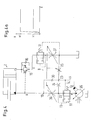
- Fig. 1 shows a hydraulic control 1, which serves to control a consumer 2, which is designed here as a piston-cylinder arrangement with a piston 3 and a cylinder 4.
- the piston 3 divides the cylinder into a first pressure chamber 5 and a second pressure chamber 6.
- the two pressure chambers 5, 6 are connected to working ports A, B of the controller 1.
- the two working connections A, B together form a working connection arrangement.
- the controller 1 has a supply connection arrangement 7, which has a high-pressure connection P, which is designed as a pump connection, a low-pressure connection T, which is designed as a tank connection, and a load-sensing connection LS.
- a control valve 8 is arranged, which has a valve slide 9 as a valve element.
- the valve spool 9 is displaceable in a total of five different operating states by means of a drive 10, which is shown only schematically, which may be designed, for example, as an electromagnetic drive or as a pilot-controlled drive. These operating states are represented by five positions ae.
- the valve spool 9 in the control valve 8 but is practically continuously movable, so that he can basically take any intermediate position.
- the control valve 8 is designed here as a proportional valve.
- valve slide 9 grooves and other recesses on its circumference, possibly bores and the like, which come into coincidence with corresponding annular grooves, recesses and holes in a housing of the control valve 8 and thereby in dependence From the position of the valve spool 9 certain connections between the supply terminal assembly 7 and the working port arrangement A, B release more or less throttled or lock.
- Examples which show the housing of such a control valve and an associated slide are known, for example, from US Pat. No. 4,981,159 mentioned in the introduction. Depending on the needs of the skilled person will be able to form such a slider and a corresponding housing.
- a compensation valve 11 is arranged between the control valve 8 and the high-pressure port P.
- the compensation valve 11 is loaded in the opening direction by the force of a spring 12 and the pressure in a control line 14.
- the compensation valve 11 is connected via a line 13 with its output, that is, a point between the compensation valve 11 and the control valve 8. In the closing direction so the input pressure of the control valve 8 acts on the compensation valve eleventh
- the working port A referred to as "lifting port”, because hydraulic fluid is fed through it in the larger pressure chamber 5, which leads to raising or extending the piston 3.
- the working connection B is referred to as a "lowering connection”.
- hydraulic fluid must be fed under pressure to lower the piston 3 again or retract.
- a load-holding valve 15 is connected, which can be controlled by the pressure at the lowering connection B.
- the load-holding valve 15 is bridged by a check valve 16 which opens toward the first pressure chamber 5.
- the lifting connection A is connected via a return compensation valve 17 to a first working outlet 18 of the control valve 8.
- the control valve 8 has a second working outlet 19, which is connected to the lowering connection B. If negative loads occur, the lifting port A is controlled by the return compensation valve 17, as is known for example from DE 102 16 958 B3.
- control valve 8 has a first load-sensing output 20 and a second load-sensing output 21.
- the first working outlet 18, the second working outlet 19, the first load-sensing outlet 20 and the second load-sensing outlet 21 are connected to the low-pressure connection T.
- the consumer 2 is thus, so to speak, in a "floating position".
- valve slide 9 In a lifting position e, the valve slide 9 is moved so that the first working outlet 18 and the first load-sensing outlet 20 is connected to the pressure input 22.
- the second pressure outlet 19 and the second load sensing port 21 are connected to the low pressure port T. Hydraulic fluid under pressure is then conveyed to the lifting port A and passes through the check valve 16 into the pressure chamber 5.
- the piston 3 moves to the right. This is a normal mode of operation.
- the second load-sensing output 21 is connected to a tap 23 of a pressure divider, which is formed by two throttles 24, 25.
- the throttle 25 is in this case arranged between the tap 23 and the low-pressure connection T.
- the throttle 24 is disposed between the tap 23 and the pressure input 22.
- the throttle 24 can be formed as a constant throttle, that is independent of the position of the valve slide flow resistance, while the flow resistance of the throttle 25 by adjusting the valve spool 9 is variable.
- the second load-sensing output 21 is connected via an aperture 26 and a shuttle valve 27 to the control line 14 in connection. Furthermore, the second load-sensing output 21 is connected to the load-sensing connection LS of the supply connection arrangement 7 via a second change-over valve 28 connected downstream of the change-over valve 27.
- the first shuttle valve 27 is connected via an aperture 26a to the first load-sensing output 20.
- the second load-sensing output 21 is connected to an input of a selection device 29. With this selection device and the second working output 19 is connected.
- the selector 29 has a check valve 30 in the line connected to the second working port 19, so that at the output 31 of the selector 29 always the greater of the two pressures at the second working port 19 and the second load sensing output 21 is present.
- the pressure at the second load-sensing output 21 is greater than the pressure at the second working output 19. This is because the valve spool 9 generates a relatively large throttle effect at the beginning of its movement with the control valve 8. In this case, the pressure at the second working port 19 is changed in proportion to the movement of the valve spool 9. This is a section P1 in FIG. In this area, the controller 1 operates as a pressure control.
- a hybrid pressure H that is, a pressure composed partly of the pressure control and partly of the flow control.
- the "FC control" area indicates that only the flow is controlled here. The pressure is automatically set. If the external conditions are different, other sequences of pressure and flow control may result.
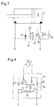
- the lowering connection B is also assigned a pilot-controlled shut-off valve 34.
- a variable displacement pump 35 which is controlled via the load-sensing connection LS.
- the control valve 8 is symbolized here only by two “large” throttles 36, 37 and the “small” throttle 25 and the throttle 24.
- the large throttles 36, 37 and the small throttle 25 are adjustable in dependence on the position of the valve spool 9 in the control valve 8.
- the compensation valve 11 is thus controlled by the pressure difference between the pressure input 22 and the tap 23.
- the pressure at the second working port 19 is then proportional to the displacement of the valve spool 9.
- the pressure is such that, at least when it has reached its maximum value, it is sufficient to open the load-holding valve 15. A higher pressure is not required to open the load-holding valve 15. In this area, the valve spool is moved by about 1 to 2 mm.
- the check valve 30, i. the selector 29 changes from the pressure control to the flow control.
- the flow to the consumer 2 is determined by the position of the valve spool 9.
- the pressure is determined by the consumer. In this area, the valve spool is moved by a further 3 to 4 mm.
- FIG. 4a A corresponding operating diagram is shown in FIG. 4a.
- a maximum pressure H2 is limited by the pressure relief valve 32. Between H1 and H2, the pressure is determined by the consumer 2.
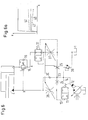
- Fig. 5 shows a modified embodiment.
- the same elements are provided with the same reference numerals.
- the check valve 30 is now replaced by a shuttle valve 38, whose one input to the second working port 19 and whose other input is connected to the tap 23. This results, as can be seen from Fig. 5a, practically the same performance.
- the shuttle valve 38 forwards the higher of the two pressures from the second working outlet 19 and tap 23 to the compensation valve 11.
- shuttle valve 38 may optionally be integrated into the valve spool 9.
- Fig. 6 an embodiment is shown schematically, which substantially corresponds to the embodiment of FIG. 4.
- the control line 14 is not only connected to the tap 23, but in addition to a relief valve 39, which opens to the tank T.
- the discharge is set depending on the consumer 2.
- a minimum pressure curve 40 which can be shifted between two limits 41, 42, results in the flow control range.
- the pressure at flow control by the consumer 2 is determined. If the pressure provided by the pressure control is too low to move the load, for example a load, then takes over the flow control.
- the controller is adapted to operate a motor for lifting a load. Accordingly, it is sufficient if the selector 29 has a check valve 30 only for the lowering connection B.
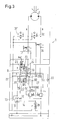
- Fig. 3 shows a controller 1, which is intended to drive a consumer 2, which can be operated in both directions and can also apply a negative load in both directions, for example, during coasting when driving forwards or backwards a rotary motor, the vehicle drives.
- Fig. 1 The essential difference from Fig. 1 is that now for both working outputs 18, 19 each have a check valve 30, 30 'is provided so that the compensation valve 11 can cause both a pressure control of the control valve 8 and a flow control in each direction of movement. Accordingly is also for the other working port A a pressure divider with two throttles 24 ', 25' and a tap 23 'is provided, wherein the tap 23' with the diaphragm 26a comes into connection when the valve spool 9 is moved to the position E.
- the two block orders b, d are not provided here.
- valve spool 9 If the valve spool 9 is in the position e, then the check valve 30 'decides, so to speak, whether the pressure at the first working output 18 or at the first load-sensing output 20 is higher and should be used via the control line 14 for controlling the compensation valve 11.
- the pressure holding valve 15 has a control input 43 which is connected to a pilot control device 44.
- the pilot control device has a slide 45 which can be displaced under the action of a pressure at the countersink B. In the illustrated non-displaced position, the control input 43 of the load-holding valve 15 is practically short-circuited or connected to the low-pressure connection T.
- a refilling of hydraulic fluid is required in sliding operation in order to avoid cavitation.
- a refill 47 is shown in Fig. 8, which can be connected to the two working ports A, B.
- the refill 47 and the controller 1 also further elements may be arranged, for example, the illustrated load-holding valve 15th
- throttling 48 49 resistances are shown, which may arise due to valve characteristics in a valve block, not shown, to which the drive 2 'is connected.
- the drive 2 ' is connected to the two working ports A, B. In addition, it is connected via two check valves 50, 51 to a common feed point 52.
- the check valves 50, 51 open in this case to the drive 2 '.
- the feed point 52 is connected to an outlet 53 of a refill valve 54.
- the refill valve 54 has a slide 55, which is acted upon by the two working ports A, B with a control pressure. If the pressure at the working port A is greater than the pressure at the working port B, then the slider 55 is shifted so that the working port B is connected to the output 53. The drive 2 ' can then suck in from the working port B with the lower pressure hydraulic fluid. This work connection will usually be connected to tank.
- the controller With the controller, one can have a load that is less than a set value of, for example, 30 bar. There is then a control according to the load level given by the consumer, in other words a flow control or regulation.
- the controller allows a "meter in” function or a “meter out” function, whereby the system itself can choose which option to use.
Abstract
Description
- Die Erfindung betrifft eine hydraulische Steuerung mit einer Versorgungsanschlußanordnung, die einen Hochdruckanschluß und einen Niederdruckanschluß aufweist, einer Arbeitsanschlußanordnung, die zwei mit einem Verbraucher verbindbare Arbeitsanschlüsse aufweist, einem Steuerventil mit einem Ventilelement zwischen der Versorgungsanschlußanordnung und der Arbeitsanschlußanordnung und einem Kompensationsventil, das zwischen dem Hochdruckanschluß und dem Steuerventil angeordnet ist und das in Schließrichtung von einem Druck zwischen dem Kompensationsventil und dem Steuerventil beaufschlagt ist. Ferner betrifft die Erfindung ein Verfahren zum Steuern eines hydraulischen Verbrauchers, der von einem Steuerventil in einer Drucksteuer-Betriebsweise gesteuert wird.
- Eine derartige hydraulische Steuerung und ein derartiges Verfahren sind aus DE 198 00 721 A1 bekannt. Das Kompensationsventil ist in Öffnungsrichtung mit einer Öffnungsfeder und von einem Druck beaufschlagt, der über eine feste Drossel abgenommen werden kann. Die feste Drossel ist Bestandteil eines Druckteilers zwischen dem Ausgang des Kompensationsventils und dem Niederdruckanschluß, der hier als Tankanschluß ausgebildet ist. Das Kompensationsventil sorgt also für eine Drucksteuerung, bei der der Motorzuflußdruck einen im wesentlichen durch die Stellung des Steuerventils bestimmten Wert hat.
- In der Rückflußleitung vom Motor zum Niederdruckanschluß ist in Reihe ein Kompensationsventil und ein Lasthalteventil angeordnet. Dem Lasthalteventil wird über eine Pilotleitung der Motorzuflußdruck in Öffnungsrichtung und über eine weitere Pilotleitung der Druck am Ausgang des Lasthalteventils zugeführt. Das Lasthalteventil stellt sich daher unter dem Einfluß einer Feder so ein, daß es erst öffnet, wenn die Druckdifferenz die Federkraft überwunden hat.
- Wenn nun dieser Motor unter Last abgesenkt wird, dann ist ein relativ hoher Zuflußdruck erforderlich. Beispielsweise muß der Schieber des Steuerventils relativ weit geöffnet werden, wobei in Abhängigkeit von seiner Gestaltung eine größere oder kleinere Schieberbewegung erforderlich ist, um den hohen Druck zu steuern. Dies ist energetisch ungünstig, weil man diesen hohen Druck im Grunde nur zum Öffnen des Lasthalteventils aufbringen muß.
- Eine andere Möglichkeit, das Kompensationsventil zu verwenden, ist in DE 102 16 958 B3 angegeben. Dort wird das Kompensationsventil durch eine Druckdifferenz über das Steuerventil gesteuert und hält die Druckdifferenz über das Steuerventil konstant. Auf diese Weise wird eine Durchflußsteuerung realisiert, bei der die dem Verbraucher zugeführte Menge abhängig von der Stellung des Ventilelements ist. Je weiter das Ventilelement verschoben wird, desto größer ist der Zu- und der Abfluß.
- US 4 981 159 zeigt nun eine hydraulische Steuerung, die mit unterschiedlichen Ventilelementen als Drucksteuerung einerseits und als Durchflußsteuerung andererseits verwendet werden kann. Hierzu ist lediglich das Ventilelement, das ebenfalls als Schieber ausgebildet ist, auszutauschen. Ein derartiger Austausch ist zwar prinzipiell nicht schwierig. Er läßt sich jedoch nur durchführen, wenn das System drucklos oder noch besser entleert ist. Ein Wechsel der Betriebsarten bedingt also doch einen gewissen Aufwand.
- Der Erfindung liegt die Aufgabe zugrunde, einen Energieverbrauch möglichst günstig zu gestalten.
- Diese Aufgabe wird bei einer hydraulischen Steuerung der eingangs genannten Art dadurch gelöst, daß das Kompensationsventil in Öffnungsrichtung von einem Druck einer Auswahleinrichtung beaufschlagbar ist, die dem Kompensationsventil wahlweise einen Drucksteuer-Druck oder einen Durchflußsteuer-Druck zuführt.
- Mit dieser Ausgestaltung ist es möglich, die hydraulische Steuerung wahlweise in einer Drucksteuer-Betriebsweise oder in einer Durchflußsteuer-Betriebsweise zu betreiben. Ein Umbau ist hierfür nicht erforderlich. Man verwendet lediglich unterschiedliche Drücke, die über die Auswahleinrichtung ausgewählt und dann gezielt dem Kompensationsventil zugeführt werden. Man kann also dann denjenigen Druck von Drucksteuer-Druck oder Durchflußsteuer-Druck auswählen, der die energetisch günstigste Betriebsweise erlaubt. Man kann die Auswahleinrichtung für beide Bewegungsrichtungen des Verbrauchers vorsehen. In vielen Fällen wird es aber ausreichen, die Auswahleinrichtung nur für eine Bewegungsrichtung, in der negative Lasten auftreten können, vorzusehen. Darüber hinaus kann man mit dieser Ausgestaltung eine sehr viel angenehmere Bedienung der Steuerung erzielen. Wenn man bislang eine negative Last absenken wollte, beispielsweise um einen Kranarm zusammenzuschieben, dann mußte man zunächst eine negative Belastung und danach eine positive Belastung aufbringen, um den Kran ganz zusammenzuschieben. Hierzu mußte man ein Bedienelement der Steuerung bewegen, um den Übergang von der negativen zur positiven Belastung zu bewältigen. Mit der neuen Ausgestaltung kann man das Bedienelement, beispielsweise einen Handgriff, in einer eingestellten Position belassen und die Steuerung wird selbst auf Durchflußsteuerung wechseln, wenn die Kraft positiv wirkt.
- Hierbei ist bevorzugt, daß die Auswahleinrichtung den höheren Druck von Drucksteuer-Druck und Durchflußsteuer-Druck dem Kompensationsventil zuführt. Dies hat zwei Vorteile. Zum einen wird die Entscheidung erleichtert, welcher der beiden Drücke ausgewählt werden soll. Zum anderen läßt sich auf diese Weise auch der Betrieb der Auswahleinrichtung automatisieren.
- Vorzugsweise gibt die Auswahleinrichtung bei einer Betätigung des Steuerventils aus einer vorbestimmten Stellung heraus zunächst den Drucksteuer-Druck und dann den Durchflußsteuer-Druck an das Kompensationsventil weiter. Bei dieser Stellung kann es sich beispielsweise um eine "Nullstellung" oder "Neutralstellung" handeln, die nachfolgend beispielhaft zur Erläuterung verwendet wird. In Abhängigkeit von der Ausgestaltung des Steuerventils kann diese vorbestimmte Stellung aber auch woanders liegen. Wenn das Steuerventil aus seiner Nullstellung herausbewegt wird, dann öffnet es zunehmend und leitet somit Hydraulikflüssigkeit vom Hochdruckanschluß, der in der Regel als Pumpenanschluß ausgebildet ist, zu einem Arbeitsanschluß weiter. In der Anfangsphase dieses Aufsteuer-Abschnitts betreibt man die Steuerung dann in einer Drucksteuerungs-Betriebsweise, bei der der Druck am Ausgang des Steuerventils im wesentlichen von der Stellung des Ventilelements des Steuerventils abhängt. Die einzelnen Drücke hängen natürlich von der genauen Ausgestaltung des Ventilelements, beispielsweise eines Ventilschiebers, ab. Die Erläuterung ist hier also beispielhaft zu verstehen. Sie dient nur zum besseren Verständnis der Erfindung. Dieser Druck kann dann beispielsweise genutzt werden, um andere Ventile in der Steuerung zu öffnen, beispielsweise ein Lasthalteventil. Dieses Lasthalteventil muß dann nur auf diesen relativ geringen Druck ausgelegt sein, der durch die Drucksteuerung ermöglicht wird. Man kann auch andersherum vorgehen und zuerst ein Lasthalteventil wählen und danach das übrige System dimensionieren. Wenn dieser Mindestdruck überschritten wird, dann schaltet die Auswahleinrichtung automatisch auf eine Durchflußsteuer-Betriebsweise um. Bei einer Durchflußsteuer-Betriebsweise wird der Druck dann praktisch ausschließlich vom Verbraucher bestimmt, d.h. man stellt nicht mehr Druck bereit, als unbedingt erforderlich ist. Das Steuerventil, das vorzugsweise als Proportionalventil ausgebildet ist, liefert dann die entsprechende Menge der Hydraulikflüssigkeit, steuert also vereinfacht gesagt die Geschwindigkeit, mit der der Verbraucher betrieben wird. Mit dieser Ausgestaltung wird also in einem Druckbereich, der nach unten durch den von der Drucksteuerung vorgegebenen Minimaldruck und nach oben gegebenenfalls durch ein Überdruckventil begrenzt ist, automatisch der energetisch günstigste Druck eingestellt, also der vom Verbraucher benötigte Druck. Letztendlich entscheiden also die äußeren Bedingungen, welche Form der Steuerung aktiv ist. Dies gilt natürlich auch in der "Anfangsphase".
- Vorzugsweise ist die Auswahleinrichtung einerseits mit einer Arbeitsleitung, die zwischen dem Steuerventil und einem Arbeitsanschluß angeordnet ist, und andererseits mit einer mit einer Lastfühlleitung in Verbindung stehenden Steuerleitung verbunden. Dies gilt natürlich dann, wenn sich das Steuerventil im Betriebszustand befindet, d.h. das Ventilelement aus seiner Ruhestellung ausgelenkt worden ist und eine Verbindung zwischen dem Kompensationsventil und einem der Arbeitsanschlüsse hergestellt hat. Mit der Betätigung des Ventilelements steigt der Druck in der Arbeitsleitung an. Solange dieser Druck kleiner ist als der Druck in der Steuerleitung, erfolgt eine Drucksteuerung. Bei der Drucksteuerung ist der Druck am Arbeitsanschluß im wesentlichen abhängig von der Stellung des Ventilelements. Wenn das Ventilelement weiter betätigt wird, wird der Druck am Arbeitsanschluß in Abhängigkeit von den äußeren Verhältnissen beispielsweise irgendwann den Druck in der Steuerleitung überschreiten. In diesem Fall erfolgt eine Durchflußsteuerung, bei der der Druck am Arbeitsanschluß durch den Druck des Verbrauchers bestimmt wird. Damit läßt sich ein energetisch außerordentlich günstiger Betrieb realisieren, weil nicht mehr Druck bereitgestellt werden muß, als zum Betrieb des Verbrauchers erforderlich ist. In der Steuerleitung gibt es sozusagen ein "künstliches Lastsignal".
- Vorzugsweise ist die Steuerleitung mit einem Abgriff eines Druckteilers verbunden, der zwischen dem Kompensationsventil und dem Niederdruckanschluß angeordnet ist. Der gleiche Druckteiler kann auch verwendet werden, um das Lastfühlsignal zu erzeugen. Allerdings ist zwischen dem Druckteiler und einem Lastfühlanschluß (LS-Anschluß) in der Regel noch eine weitere Drossel angeordnet, um eine gewisse Entkopplung zu bewirken. An dem Abgriff des Druckteilers wird ein Druck abgenommen, der das Kompensationsventil in Öffnungsrichtung beaufschlagt. Dies ist eine relativ einfache Konstruktion, um die Drucksteuerung bewirken zu können.
- Bevorzugterweise weist der Druckteiler mindestens zwei Drosseln auf, von denen eine durch das Ventilelement des Steuerventils verstellbar ist. Diese Drossel ist in der Regel die Drossel zwischen dem Abgriff und dem Niederdruckanschluß.
- In einer weiter bevorzugten Ausgestaltung weist der Druckteiler zwei Drosseln auf, die beide mit dem Ventilelement des Steuerventils verstellbar sind. Wenn die Drosseln des Druckteilers einen konstanten Wert haben, dann bleibt der Druck am Ausgang des Steuerventils im Drucksteuerbereich im wesentlichen konstant. Wenn diese Drosseln einen veränderbaren Wert haben, dann kann man den Druck anheben oder absenken.
- In einer bevorzugten Ausgestaltung weist die Auswahleinrichtung ein Rückschlagventil auf, das in Richtung auf das Kompensationsventil öffnet. Dies ist eine relativ einfache Ausgestaltung, die jedoch ausreicht, wenn man lediglich den höheren der beiden Drücke an das Kompensationsventil weiterleiten will.
- Hierbei ist bevorzugt, daß das Rückschlagventil im Ventilelement des Steuerventils angeordnet ist. In diesem Fall muß man nur wenig Änderungen an der Steuerung an sich vornehmen. Lediglich eine kleine Änderung im Ventilelement des Steuerventils ist erforderlich.
- Auch kann die Auswahleinrichtung ein Wechselventil aufweisen. Ein Wechselventil ist sozusagen ein Rückschlagventil mit zwei Rückschlagventil-Funktionen. Auch ein derartiges Wechselventil kann im Ventilelement des Steuerventils angeordnet sein.
- Vorzugsweise ist an mindestens einem Arbeitsanschluß ein Lasthalteventil angeordnet, das über eine Pilotsteuereinrichtung vom Druck am anderen Arbeitsanschluß aufsteuerbar ist. Ein derartiges Lasthalteventil wird auch als "Overcenter"-Ventil bezeichnet. Für ein derartiges Lasthalteventil ist ein vorbestimmter Öffnungsdruck erforderlich. Dieser Öffnungsdruck kann nicht zu klein gemacht werden, damit das Lasthalteventil nicht versehentlich öffnet, wenn sich aufgrund von Leckagen oder anderer widriger Umstände ein Druckaufbau ergibt, der zum Öffnen des Lasthalteventils führt. Mit einer Pilotsteuereinrichtung kann man nun den Öffnungsdruck des Lasthalteventils relativ hoch halten und dabei den notwendigen Sicherheitsabstand zu sich parasitär aufbauenden Drücken einhalten, ohne den energetischen Aufwand zum Öffnen des Lasthalteventils zu hoch treiben zu müssen. Man muß zum Öffnen des Lasthalteventils lediglich einen Druck am anderen Arbeitsanschluß aufbauen, der ausreicht, um die Pilotsteuereinrichtung zu betätigen. Ein derartiger Druck kann beispielsweise dem Minimum-Druck entsprechen, der durch die Drucksteuerung vorgegeben ist. Zum Absenken einer Last muß man also nicht mehr Druck aufbauen als unbedingt erforderlich. Dieser Druck kann beispielsweise dem Druck der Öffnungsfeder am Kompensationsventil plus dem Druck am Abgriff des Druckteilers vor dem Steuerventil entsprechen. Selbstverständlich läßt sich auch in einer derartigen Ausgestaltung ein Rücklauf-Kompensationsventil zwischen dem Verbraucher oder dem Arbeitsanschluß und dem Steuerventil verwenden.
- Hierbei ist bevorzugt, daß die Pilotsteuereinrichtung ein vom Druck am anderen Arbeitsanschluß ansteuerbares Pilot-Ventilelement aufweist, das im angesteuerten Zustand eine Verbindung von dem einen Arbeitsanschluß zu einem Steuereingang des Lasthalteventils herstellt und im nicht angesteuerten Zustand unterbricht. Dies ist eine relativ einfache Ausgestaltung einer Pilotsteuereinrichtung.
- Vorzugsweise ist die Arbeitsanschlußanordnung mit einer Nachsaugeinrichtung verbunden, die ein Nachfüllventil mit einem Nachfüllventilelement aufweist, das von einem Druck an einem Arbeitsanschluß verlagerbar ist und eine Verbindung zwischen einem Verbraucheranschluß und dem anderen Arbeitsanschluß herstellt. Die Verbindung kann dabei so erfolgen, daß zum Verbraucher hin praktisch keine Restriktionen mehr durch Drosseln, Engstellen in einem Ventilblock oder ähnliches vorhanden sind. Dementsprechend kann das Nachfüllen mit einem niedrigeren Druck als bisher erfolgen, so daß man in einem schiebenden Betrieb, also bei einem Betrieb mit negativen Lasten, ebenfalls mit relativ wenig zusätzlicher Energie auskommt.
- Bevorzugterweise ist der Ausgang der Auswahleinrichtung mit einem Druckbegrenzungsventil verbunden. Über das Druckbegrenzungsventil, das in Abhängigkeit von der Anwendung eingestellt wird, läßt sich dann beispielsweise der Drucksteuer-Druck mit der Veränderung der Stellung des Ventilelements des Steuerventils anheben oder absenken.
- Die Aufgabe wird bei einem Verfahren der eingangs genannten Art dadurch gelöst, daß der Verbraucher von dem Steuerventil alternativ in einer Durchflußsteuer-Betriebsweise gesteuert wird und die Umschaltung zwischen Drucksteuer- und Durchflußsteuer-Betriebsweise automatisch in Abhängigkeit von den herrschenden Drükken erfolgt.
- Damit ist es möglich, den Verbraucher in einem energetisch günstigen Bereich zu fahren. In der Durchflußsteuer-Betriebsweise wird der Druck vom Verbraucher bestimmt. In der Drucksteuer-Betriebsweise wird der Druck vom Steuerventil bestimmt. Der Übergang zwischen diesen beiden Betriebsweisen richtet sich dann nach den Drükken am Verbraucheranschluß. Beispielsweise kann man hierfür die oben erwähnte Auswahleinrichtung verwenden. Man kann eine derartige Vorgehensweise aber auch auf andere Weise realisieren, beispielsweise mit elektrisch angesteuerten Komponenten.
- Die Erfindung wird im folgenden anhand von bevorzugten Ausführungsbeispielen in Verbindung mit der Zeichnung beschrieben. Hierin zeigen:
- Fig. 1
- ein erstes Ausführungsbeispiel einer hydrau-lischen Steuerung,
- Fig. 2
- eine schematische Darstellung zur Erläuterung der Druckverhältnisse,
- Fig. 3
- ein zweites Ausführungsbeispiel der hydrauli-schen Steuerung,
- Fig. 4
- eine vereinfachte Darstellung eines weiteren Ausführungsbeispiels der hydraulischen Steuerung,
- Fig. 5
- eine gegenüber Fig. 4 abgewandelte Ausführungsform,
- Fig. 6
- eine gegenüber Fig. 4 abgewandelte Ausführungsform,
- Fig. 7
- eine schematische Darstellung eines Verbrau-chers mit einem Lasthalteventil und
- Fig. 8
- eine schematische Darstellung einer Nachsaug-einrichtung.
- Fig. 1 zeigt eine hydraulische Steuerung 1, die zur Ansteuerung eines Verbrauchers 2 dient, der hier als Kolben-Zylinder-Anordnung mit einem Kolben 3 und einem Zylinder 4 ausgebildet ist. Der Kolben 3 teilt den Zylinder in einen ersten Druckraum 5 und einen zweiten Druckraum 6. Die beiden Druckräume 5, 6 sind mit Arbeitsanschlüssen A, B der Steuerung 1 verbunden. Die beiden Arbeitsanschlüsse A, B bilden zusammen eine Arbeitsanschlußanordnung.
- Die Steuerung 1 weist eine Versorgungsanschlußanordnung 7 auf, die einen Hochdruckanschluß P, der als Pumpenanschluß ausgebildet ist, einen Niederdruckanschluß T, der als Tankanschluß ausgebildet ist, und einen Lastfühlanschluß LS aufweist.
- Zwischen der Versorgungsanschlußanordnung 7 und der Arbeitsanschlußanordnung A, B ist ein Steuerventil 8 angeordnet, das einen Ventilschieber 9 als Ventilelement aufweist. Der Ventilschieber 9 ist durch einen nur schematisch dargestellten Antrieb 10, der beispielsweise als elektromagnetischer Antrieb oder als pilotgesteuerter Antrieb ausgebildet sein kann, in insgesamt fünf unterschiedliche Betriebszustände verlagerbar. Diese Betriebszustände sind durch fünf Stellungen a-e dargestellt. Tatsächlich ist der Ventilschieber 9 im Steuerventil 8 aber praktisch kontinuierlich bewegbar, so daß er im Grunde jede Zwischenstellung einnehmen kann. Das Steuerventil 8 ist hier als Proportionalventil ausgebildet.
- In an sich bekannter und daher nicht näher beschriebener Weise weist der Ventilschieber 9 Nuten und andere Ausnehmungen an seinem Umfang, gegebenenfalls Bohrungen und ähnliches, auf, die mit entsprechenden Ringnuten, Ausnehmungen und Bohrungen in einem Gehäuse des Steuerventils 8 in Überdeckung kommen und dabei in Abhängigkeit von der Stellung des Ventilschiebers 9 bestimmte Verbindungen zwischen der Versorgungsanschlußanordnung 7 und der Arbeitsanschlußanordnung A, B mehr oder weniger gedrosselt freigeben oder sperren. Beispiele, die das Gehäuse eines derartigen Steuerventils und einen dazugehörigen Schieber zeigen, sind beispielsweise aus der eingangs erwähnten US 4 981 159 bekannt. In Abhängigkeit von den Bedürfnissen wird der Fachmann einen derartigen Schieber und ein entsprechendes Gehäuse ausbilden können.
- Zwischen dem Steuerventil 8 und dem Hochdruckanschluß P ist ein Kompensationsventil 11 angeordnet. Das Kompensationsventil 11 ist in Öffnungsrichtung durch die Kraft einer Feder 12 und den Druck in einer Steuerleitung 14 belastet. In Schließrichtung ist das Kompensationsventil 11 über eine Leitung 13 mit seinem Ausgang verbunden, also einem Punkt zwischen dem Kompensationsventil 11 und dem Steuerventil 8. In Schließrichtung wirkt also der Eingangsdruck des Steuerventils 8 auf das Kompensationsventil 11.
- Von den beiden Arbeitsanschlüssen A, B wird, um die nachfolgende Erläuterung zu vereinfachen, der Arbeitsanschluß A als "Hebeanschluß" bezeichnet, weil über ihn Hydraulikflüssigkeit in den größeren Druckraum 5 eingespeist wird, was zum Anheben oder Ausfahren des Kolbens 3 führt. Der Arbeitsanschluß B wird hingegen als "Senkanschluß" bezeichnet. Hier muß Hydraulikflüssigkeit unter Druck eingespeist werden, um den Kolben 3 wieder absenken oder einfahren zu können. Mit dem Hebeanschluß A ist ein Lasthalteventil 15 verbunden, das vom Druck am Senkanschluß B aufgesteuert werden kann. Das Lasthalteventil 15 ist durch ein zum ersten Druckraum 5 hin öffnendes Rückschlagventil 16 überbrückt.
- Der Hebeanschluß A ist über ein Rücklauf-Kompensationsventil 17 mit einem ersten Arbeitsausgang 18 des Steuerventils 8 verbunden. Das Steuerventil 8 weist einen zweiten Arbeitsausgang 19 auf, der mit dem Senkanschluß B verbunden ist. Wenn negative Lasten auftreten, wird der Hebeanschluß A vom Rücklauf-Kompensationsventil 17 gesteuert, wie dies beispielsweise aus DE 102 16 958 B3 bekannt ist.
- Ferner weist das Steuerventil 8 einen ersten Lastfühlausgang 20 und einen zweiten Lastfühlausgang 21 auf. In der dargestellten Neutralstellung c des Ventilelements 9 sind der erste Arbeitsausgang 18, der zweite Arbeitsausgang 19, der erste Lastfühlausgang 20 und der zweite Lastfühlausgang 21 mit dem Niederdruckanschluß T verbunden. Der Verbraucher 2 befindet sich also sozusagen in einer "Schwimmstellung".
- Der Neutralstellung c benachbart angeordnet sind Blokkierstellungen b, d des Ventilelements 9, in denen lediglich die beiden Lastfühlausgänge 20, 21 mit dem Niederdruckanschluß T verbunden sind. Die beiden Arbeitsausgänge 18, 19 sind hingegen blockiert. In allen drei bisher besprochenen Stellungen b, c, d ist ein Druckeingang 22 des Steuerventils 8 blockiert. Der Druckeingang 22 ist mit dem Ausgang des Kompensationsventils 11 verbunden.
- In einer Hebestellung e wird der Ventilschieber 9 so verschoben, daß der erste Arbeitsausgang 18 und der erste Lastfühlausgang 20 mit dem Druckeingang 22 verbunden wird. Der zweite Druckausgang 19 und der zweite Lastfühlanschluß 21 werden mit dem Niederdruckanschluß T verbunden. Hydraulikflüssigkeit unter Druck wird dann zum Hebeanschluß A gefördert und gelangt über das Rückschlagventil 16 in den Druckraum 5. Der Kolben 3 bewegt sich nach rechts. Dies ist eine an und für sich normale Betriebsweise.
- In einer Senkstellung a wird hingegen der zweite Arbeitsausgang 19 mit dem Druckeingang 22 verbunden, während der erste Arbeitsausgang 18 und der erste Lastfühlausgang 20 mit dem Niederdruckanschluß T verbunden werden.
- Der zweite Lastfühlausgang 21 ist mit einem Abgriff 23 eines Druckteilers verbunden, der durch zwei Drosseln 24, 25 gebildet ist. Die Drossel 25 ist hierbei zwischen dem Abgriff 23 und dem Niederdruckanschluß T angeordnet. Die Drossel 24 ist zwischen dem Abgriff 23 und dem Druckeingang 22 angeordnet. Die Drossel 24 kann als konstante Drossel ausgebildet sein, also einen von der Stellung des Ventilschiebers unabhängigen Strömungswiderstand aufweisen, während der Strömungswiderstand der Drossel 25 durch Verstellen des Ventilschiebers 9 veränderbar ist. Der zweite Lastfühlausgang 21 steht über eine Blende 26 und ein Wechselventil 27 mit der Steuerleitung 14 in Verbindung. Ferner steht der zweite Lastfühlausgang 21 über ein dem Wechselventil 27 nachgeschaltetes zweites Wechselventil 28 mit dem Lastfühlanschluß LS der Versorgungsanschlußanordnung 7 in Verbindung.
- Das erste Wechselventil 27 ist über eine Blende 26a mit dem ersten Lastfühlausgang 20 verbunden.
- Der zweite Lastfühlausgang 21 ist mit einem Eingang einer Auswahleinrichtung 29 verbunden. Mit dieser Auswahleinrichtung ist auch der zweite Arbeitsausgang 19 verbunden. Die Auswahleinrichtung 29 weist ein Rückschlagventil 30 in der mit dem zweiten Arbeitsausgang 19 verbundenen Leitung auf, so daß am Ausgang 31 der Auswahleinrichtung 29 immer der größere der beiden Drücke am zweiten Arbeitsausgang 19 und am zweiten Lastfühlausgang 21 ansteht.
- Dies hat folgende Wirkung: Wenn der Ventilschieber 9 in seine Senkstellung a verschoben wird, dann wird der Senkausgang B mit Druck versorgt. Gleichzeitig steuert der Druck am Senkausgang B das Lasthalteventil 15 auf, so daß Hydraulikflüssigkeit unter Druck aus dem Druckraum 5 entweichen kann. Das Kompensationsventil 11 wird dabei auf zwei unterschiedliche Arten gesteuert, die wiederum von den äußeren Verhältnissen abhängen. Dies soll am folgenden Beispiel erläutert werden:
- Zunächst ist der Druck am zweiten Lastfühlausgang 21 größer als der Druck am zweiten Arbeitsausgang 19. Dies liegt daran, daß der Ventilschieber 9 zu Beginn seiner Bewegung mit dem Steuerventil 8 eine relativ große Drosselwirkung erzeugt. In diesem Fall wird der Druck am zweiten Arbeitsausgang 19 proportional zur Bewegung des Ventilschiebers 9 verändert. Dies ist in Fig. 2 ein Abschnitt P1. In diesem Bereich arbeitet die Steuerung 1 als Drucksteuerung. Sobald aber aufgrund einer weiteren Bewegung des Ventilschiebers 9 die Drosselwirkung zwischen dem Ventilschieber 9 und dem Gehäuse des Steuerventils 8 geringer wird und der Druck am zweiten Arbeitsausgang 19 über den Druck am zweiten Lastfühlausgang 21 ansteigt, wird dieser Druck zur Steuerung des Kompensationsventils 11 verwendet und das Steuerventil 8 arbeitet als Durchfluß-Steuerventil, d.h. der Durchfluß wird nun in Abhängigkeit von der Stellung des Ventilschiebers 9 im Steuerventil 9 eingestellt. Der Druck hingegen wird vom Verbraucher 2 bestimmt. Die Obergrenze wird durch ein Überdruckventil 32 festgelegt. Ein entsprechendes Überdruckventil 32' ist auch am anderen Arbeitsanschluß A vorgesehen.
- Wenn die Drossel 24 zwischen dem Druckeingang 22 und dem Abgriff 23 ebenfalls variabel ausgebildet ist, d.h. sich mit der Stellung des Ventilschiebers 9 im Steuerventil 8 verändert, dann ergibt sich die in Fig. 2 dargestellte untere Rampe 33, die den Mindestdruck des Steuerventils in Abhängigkeit von der Auslenkung x des Schiebers darstellt. Nach oben ist in Fig. 2 ein Hybriddruck H aufgetragen, d.h. ein Druck, der sich teils aus der Drucksteuerung und teils aus der Durchflußsteuerung zusammensetzt. Durch den Bereich "FC control" ist angegeben, daß hier nur der Durchfluß gesteuert wird. Der Druck stellt sich automatisch ein. Wenn die äußeren Verhältnisse anders sind, können sich auch andere Abfolgen von Druck- und Durchflußsteuerung ergeben.
- In an sich bekannter Weise ist dem Senkanschluß B ebenfalls ein pilotgesteuertes Sperrventil 34 zugeordnet.
- Anhand von Fig. 4 soll die Funktionsweise noch einmal erläutert werden. Gleiche Teile sind mit den gleichen Bezugszeichen versehen. Zusätzlich dargestellt ist noch eine Verstellpumpe 35, die über den Lastfühlanschluß LS gesteuert wird. Das Steuerventil 8 ist hier lediglich durch zwei "große" Drosseln 36, 37 und die "kleine" Drossel 25 sowie die Drossel 24 symbolisiert. Die großen Drosseln 36, 37 und die kleine Drossel 25 sind in Abhängigkeit von der Stellung des Ventilschiebers 9 im Steuerventil 8 verstellbar.
- Wenn der Ventilschieber 9 im Steuerventil 8 verschoben wird, dann öffnen sich die Drosseln 36, 37 und die Drossel 25 schließt. Dies führt zu der in Fig. 2 dargestellten ansteigenden Kurve für den Minimaldruck. Wenn die Drossel 25 öffnet, ergibt sich eine fallende Kurve. Wenn die Drossel 36 noch wenig geöffnet ist, also einen großen Widerstand aufweist, dann ist in Abhängigkeit von den äußeren Bedingungen, also den übrigen Drücken im System, beispielsweise der Druck am zweiten Arbeitsausgang 19 kleiner als am Druckeingang 22. Über die feste Drossel 24 ergibt sich nur ein geringer Druckabfall, weil die variable Drossel 25 zu Beginn der Bewegung des Ventilschiebers 9 nur wenig geöffnet ist. Dementsprechend ist der Druck am Abgriff 23 höher als der Druck am zweiten Arbeitsausgang 19 und das Rückschlagventil 30, das, wie dargestellt, auch im Ventilschieber 9 angeordnet sein kann, bleibt geschlossen. Das Kompensationsventil 11 wird also durch die Druckdifferenz zwischen dem Druckeingang 22 und dem Abgriff 23 gesteuert. Der Druck am zweiten Arbeitsausgang 19 ist dann proportional zur Verlagerung des Ventilschiebers 9. Der Druck ist so bemessen, daß er zumindest dann, wenn er seinen Maximalwert erreicht hat, ausreicht, um das Lasthalteventil 15 zu öffnen. Ein höherer Druck ist nicht erforderlich, um das Lasthalteventil 15 zu öffnen. In diesem Bereich wird der Ventilschieber um etwa 1 bis 2 mm bewegt.
- Wenn nun der Drosselwiderstand der Drossel 36 weiter abnimmt, steigt der Druck am zweiten Arbeitsausgang 19 an, und zwar so lange, bis er den Druck am Abgriff 23 übersteigt. In diesem Fall öffnet das Rückschlagventil 30, d.h. die Auswahleinrichtung 29 geht von der Drucksteuerung zur Durchflußsteuerung über. Sobald das Rückschlagventil 30 geöffnet hat, wird der Durchfluß zum Verbraucher 2 durch die Stellung des Ventilschiebers 9 bestimmt. Der Druck hingegen wird durch den Verbraucher bestimmt. In diesem Bereich wird der Ventilschieber um weitere 3 bis 4 mm bewegt.
- Damit ergibt sich ein sehr energiesparender Betrieb. Ein entsprechendes Betriebsdiagramm ist in Fig. 4a dargestellt. Man erreicht auf jeden Fall einen Mindestdruck H1. Dieser Mindestdruck ist durch die Druckteilung zwischen den Drosseln 24 und 25 vorgegeben. Ein Höchstdruck H2 wird durch das Überdruckventil 32 beschränkt. Zwischen H1 und H2 wird der Druck durch den Verbraucher 2 bestimmt.
- Fig. 5 zeigt eine abgewandelte Ausführungsform. Gleiche Elemente sind mit den gleichen Bezugszeichen versehen. Das Rückschlagventil 30 ist nun ersetzt durch ein Wechselventil 38, dessen einer Eingang mit dem zweiten Arbeitsausgang 19 und dessen anderer Eingang mit dem Abgriff 23 verbunden ist. Hier ergibt sich, wie aus Fig. 5a zu erkennen ist, praktisch das gleiche Betriebsverhalten. Das Wechselventil 38 leitet den höheren der beiden Drücke vom zweiten Arbeitsausgang 19 und Abgriff 23 an das Kompensationsventil 11 weiter.
- Auch das Wechselventil 38 kann gegebenenfalls in den Ventilschieber 9 integriert werden.
- In Fig. 6 ist ein Ausführungsbeispiel schematisch dargestellt, das im wesentlichen dem Ausführungsbeispiel der Fig. 4 entspricht. Hier ist die Steuerleitung 14 nicht nur mit dem Abgriff 23 verbunden, sondern zusätzlich mit einem Entlastungsventil 39, das zum Tank T hin öffnet. Die Entlastung wird in Abhängigkeit vom Verbraucher 2 eingestellt. Dadurch ergibt sich, wie in Fig. 6a dargestellt, im Durchflußsteuerbereich eine Minimum-Druckkurve 40, die zwischen zwei Grenzen 41, 42 verschoben werden kann.
- In allen drei Ausgestaltungen wird der Druck bei Durchflußsteuerung durch den Verbraucher 2 bestimmt. Wenn der von der Drucksteuerung bereitgestellte Druck zu gering ist, um den Verbraucher zu bewegen, beispielsweise eine Last, dann übernimmt die Durchflußsteuerung.
- Bei der Drucksteuerung ergibt sich ein Minimaldruck, der durch die Drossel 24 bestimmt ist. Dieser Minimaldruck wird so eingestellt, daß er ausreicht, um das Lasthalteventil 15 zu öffnen. Eine Möglichkeit, um diesen Druck am Senkanschluß B zu vermindern, wird weiter unten im Zusammenhang mit Fig. 7 besprochen werden.
- In Fig. 1 ist die Steuerung so ausgebildet, daß sie einen Motor zum Heben einer Last betätigen kann. Dementsprechend reicht es aus, wenn die Auswahleinrichtung 29 nur für den Senkanschluß B ein Rückschlagventil 30 aufweist.
- Fig. 3 zeigt eine Steuerung 1, die zum Antrieb eines Verbrauchers 2 gedacht ist, der in beide Richtungen betätigt werden kann und der auch in beiden Richtungen eine negative Last aufbringen kann, beispielsweise im Schiebebetrieb bei Vorwärts- oder Rückwärtsfahrt eines Rotationsmotors, der ein Fahrzeug antreibt.
- Gleiche Teile sind mit den gleichen Bezugszeichen wie in Fig. 1 versehen.
- Der wesentliche Unterschied zu Fig. 1 besteht darin, daß nun für beide Arbeitsausgänge 18, 19 jeweils ein Rückschlagventil 30, 30' vorgesehen ist, so daß das Kompensationsventil 11 in jeder Bewegungsrichtung sowohl eine Drucksteuerung des Steuerventils 8 als auch eine Durchflußsteuerung bewirken kann. Dementsprechend ist auch für den anderen Arbeitsanschluß A ein Druckteiler mit zwei Drosseln 24', 25' und einem Abgriff 23' vorgesehen, wobei der Abgriff 23' mit der Blende 26a in Verbindung kommt, wenn der Ventilschieber 9 in die Stellung E verfahren wird. Die beiden Blockadestellungen b, d sind hier nicht vorgesehen.
- Wenn sich der Ventilschieber 9 in der Stellung e befindet, dann entscheidet das Rückschlagventil 30' sozusagen, ob der Druck am ersten Arbeitsausgang 18 oder am ersten Lastfühlausgang 20 höher ist und über die Steuerleitung 14 zur Steuerung des Kompensationsventils 11 verwendet werden soll.
- Wenn nun am Senkanschluß B immer nur der niedrigstmögliche Druck ansteht, könnte es natürlich schwierig werden, das Lasthalteventil 15 zu öffnen. Eine Abhilfe hierfür wird in Fig. 7 dargestellt.
- Das Druckhalteventil 15 weist einen Steuereingang 43 auf, der mit einer Pilotsteuereinrichtung 44 verbunden ist. Die Pilotsteuereinrichtung weist einen Schieber 45 auf, der unter der Wirkung eines Drucks am Senkanschluß B verschoben werden kann. In der dargestellten nicht verschobenen Position wird der Steuereingang 43 des Lasthalteventils 15 praktisch kurzgeschlossen oder mit dem Niederdruckanschluß T verbunden.
- Wenn nun der Druck am Senkanschluß B auf einen vorbestimmten Wert ansteigt, dann wird der Schieber 45 verschoben und verbindet über ein Wechselventil 46 den Druckraum 5 mit dem Steuereingang 43. In diesem Fall wird das Lasthalteventil 15 aufgesteuert. Gleichzeitig sind nur relativ geringe Drücke am Senkanschluß B erforderlich.
- Bei einem Transmissionsantrieb 2' ist im schiebenden Betrieb ein Nachfüllen von Hydraulikflüssigkeit erforderlich, um Kavitation zu vermeiden. Um diese Nachfüllung bei niedrigen Drücken bewirken zu können, ist in Fig. 8 eine Nachfülleinrichtung 47 dargestellt, die mit den beiden Arbeitsanschlüssen A, B verbunden werden kann. Selbstverständlich können zwischen der Nachfülleinrichtung 47 und der Steuerung 1 auch noch weitere Elemente angeordnet sein, beispielsweise das dargestellte Lasthalteventil 15.
- Durch Drosseln 48, 49 sind Widerstände dargestellt, die sich aufgrund von Ventilcharakteristiken in einem nicht näher dargestellten Ventilblock ergeben können, an den der Antrieb 2' angeschlossen ist.
- Der Antrieb 2' ist mit den beiden Arbeitsanschlüssen A, B verbunden. Darüber hinaus ist er über zwei Rückschlagventile 50, 51 mit einem gemeinsamen Einspeisepunkt 52 verbunden. Die Rückschlagventile 50, 51 öffnen hierbei zum Antrieb 2'.
- Der Einspeisepunkt 52 ist mit einem Ausgang 53 eines Nachfüllventils 54 verbunden. Das Nachfüllventil 54 weist einen Schieber 55 auf, der von den beiden Arbeitsanschlüssen A, B mit einem Steuerdruck beaufschlagt wird. Wenn der Druck am Arbeitsanschluß A größer ist als der Druck am Arbeitsanschluß B, dann wird der Schieber 55 so verschoben, daß der Arbeitsanschluß B mit dem Ausgang 53 verbunden wird. Der Antrieb 2' kann dann aus dem Arbeitsanschluß B mit dem niedrigeren Druck Hydraulikflüssigkeit nachsaugen. Dieser Arbeitsanschluß wird in der Regel mit Tank verbunden sein.
- Wenn die Verhältnisse umgekehrt sind, dann schiebt der Druck am Arbeitsanschluß B den Schieber 55 so, daß der Ausgang 53 mit dem Arbeitsanschluß A verbunden wird, und der Antrieb 2' kann Hydraulikflüssigkeit aus dem Arbeitsanschluß A mit niedrigerem Druck ansaugen.
- Da die Einspeisung hinter den Drossel 48, 49 und somit mit relativ geringen Widerständen erfolgt, ist für das Nachfüllen nur ein relativ geringer Druck erforderlich. Wenn man bislang etwa 50 bar für das Nachfüllen rechnete, um die Drosselverluste an den Drosseln 48, 49 zu berücksichtigen (das sind parasitäre Verluste), dann kann man nun beispielsweise mit 30 bar auskommen.
- Mit der Steuerung kann man eine Belastung haben, die kleiner ist als ein eingestellter Wert von beispielsweise 30 bar. Über diese Belastung gibt es dann eine Regelung nach dem Belastungsniveau, das vom Verbraucher vorgegeben ist, mit anderen Worten eine Durchflußsteuerung oder -regelung.
- Die Steuerung erlaubt eine "meter in"-Funktion bzw. eine "meter out"-Funktion, wobei das System selbst wählen kann, welche Möglichkeit zu nutzen ist.
- Bei einem Transmissionsantrieb 2' kann bei negativen Lasten immer ein positiver Druck am Eingang vorhanden sein, um gegen Kavitation zu sichern. Bei einer Zylinderanwendung (Fig. 1) kann man dafür sorgen, daß das Lasthalteventil 15 mit Hilfe des definierten Minimaldrucks außer Funktion gesetzt wird, also geöffnet werden kann, wenn die Last negativ ist. Auch hier kommt praktisch keine Kavitation vor.
Claims (15)
- Hydraulische Steuerung mit einer Versorgungsanschlußanordnung, die einen Hochdruckanschluß und einen Niederdruckanschluß aufweist, einer Arbeitsanschlußanordnung, die zwei mit einem Verbraucher verbindbare Arbeitsanschlüsse aufweist, einem Steuerventil mit einem Ventilelement zwischen der Versorgungsanschlußanordnung und der Arbeitsanschlußanordnung und einem Kompensationsventil, das zwischen dem Hochdruckanschluß und dem Steuerventil angeordnet ist und das in Schließrichtung von einem Druck zwischen dem Kompensationsventil und dem Steuerventil beaufschlagt ist, dadurch gekennzeichnet, daß das Kompensationsventil (11) in Öffnungsrichtung von einem Druck einer Auswahleinrichtung (29, 30, 30', 38) beaufschlagbar ist, die dem Kompensationsventil (11) wahlweise einen Drucksteuer-Druck oder einen Durchflußsteuer-Druck zuführt.
- Hydraulische Steuerung nach Anspruch 1, dadurch gekennzeichnet, daß die Auswahleinrichtung (29, 30, 30', 38) den höheren Druck von Drucksteuer-Druck und Durchflußsteuer-Druck dem Kompensationsventil (11) zuführt.
- Hydraulische Steuerung nach Anspruch 1 oder 2, dadurch gekennzeichnet, daß die Auswahleinrichtung (29, 30, 30', 38) bei einer Betätigung des Steuerventils aus einer vorbestimmten Stellung heraus zunächst den Drucksteuer-Druck und dann den Durchflußsteuer-Druck an das Kompensationsventil weitergibt.
- Hydraulische Steuerung nach einem der Ansprüche 1 bis 3, dadurch gekennzeichnet, daß die Auswahleinrichtung (29, 30, 30', 38) einerseits mit einer Arbeitsleitung, die zwischen dem Steuerventil (8) und einem Arbeitsanschluß (A, B) angeordnet ist, und andererseits mit einer mit einer Lastfühlleitung in Verbindung stehenden Steuerleitung (14) verbunden ist.
- Hydraulische Steuerung nach Anspruch 4, dadurch gekennzeichnet, daß die Steuerleitung (14) mit einem Abgriff (23) eines Druckteilers (24, 25) verbunden ist, der zwischen dem Kompensationsventil (11) und dem Niederdruckanschluß (T) angeordnet ist.
- Hydraulische Steuerung nach Anspruch 5, dadurch gekennzeichnet, daß der Druckteiler (24, 25) mindestens zwei Drosseln aufweist, von denen eine durch das Ventilelement (9) des Steuerventils (8) verstellbar ist.
- Hydraulische Steuerung nach Anspruch 5 oder 6, dadurch gekennzeichnet, daß der Druckteiler (24, 25) zwei Drosseln aufweist, die beide mit dem Ventilelement (9) des Steuerventils (8) verstellbar sind.
- Hydraulische Steuerung nach einem der Ansprüche 1 bis 7, dadurch gekennzeichnet, daß die Auswahleinrichtung (29, 30, 30', 38) ein Rückschlagventil (30, 30') aufweist, das in Richtung auf das Kompensationsventil (11) öffnet.
- Hydraulische Steuerung nach Anspruch 8, dadurch gekennzeichnet, daß das Rückschlagventil (30, 30') im Ventilelement (9) des Steuerventils (8) angeordnet ist.
- Hydraulische Steuerung nach einem der Ansprüche 1 bis 9, dadurch gekennzeichnet, daß die Auswahleinrichtung (29, 30, 30', 38) ein Wechselventil (38) aufweist.
- Hydraulische Steuerung nach einem der Ansprüche 1 bis 10, dadurch gekennzeichnet, daß an mindestens einem Arbeitsanschluß (A) ein Lasthalteventil (15) angeordnet ist, das über eine Pilotsteuereinrichtung (44) vom Druck am anderen Arbeitsanschluß (B) aufsteuerbar ist.
- Hydraulische Steuerung nach Anspruch 11, dadurch gekennzeichnet, daß die Pilotsteuereinrichtung (44) ein vom Druck am anderen Arbeitsanschluß (B, A) ansteuerbares Pilot-Ventilelement (45) aufweist, das im angesteuerten Zustand eine Verbindung von dem einen Arbeitsanschluß (A, B) zu einem Steuereingang (43) des Lasthalteventils (15) herstellt und im nicht angesteuerten Zustand unterbricht.
- Hydraulische Steuerung nach einem der Ansprüche 1 bis 12, dadurch gekennzeichnet, daß die Arbeitsanschlußanordnung (A, B) mit einer Nachsaugeinrichtung (47) verbunden ist, die ein Nachfüllventil (54) mit einem Nachfüllventilelement (55) aufweist, das von einem Druck an einem Arbeitsanschluß (A, B) verlagerbar ist und eine Verbindung zwischen einem Verbraucheranschluß (53) und dem anderen Arbeitsanschluß (B, A) herstellt.
- Hydraulische Steuerung nach einem der Ansprüche 1 bis 13, dadurch gekennzeichnet, daß der Ausgang der Auswahleinrichtung (29, 30, 30', 38) mit einem Druckbegrenzungsventil (39) verbunden ist.
- Verfahren zum Steuern eines hydraulischen Verbrauchers, der von einem Steuerventil in einer Drucksteuer-Betriebsweise gesteuert wird, dadurch gekennzeichnet, daß der Verbraucher von dem Steuerventil alternativ in einer Durchflußsteuer-Betriebsweise gesteuert wird und die Umschaltung zwischen Drucksteuer- und Durchflußsteuer-Betriebsweise automatisch in Abhängigkeit von den herrschenden Drücken erfolgt.
Applications Claiming Priority (1)
| Application Number | Priority Date | Filing Date | Title |
|---|---|---|---|
| DE102004063044A DE102004063044B4 (de) | 2004-12-22 | 2004-12-22 | Hydraulische Steuerung |
Publications (2)
| Publication Number | Publication Date |
|---|---|
| EP1710445A2 true EP1710445A2 (de) | 2006-10-11 |
| EP1710445A3 EP1710445A3 (de) | 2009-08-12 |
Family
ID=35851427
Family Applications (1)
| Application Number | Title | Priority Date | Filing Date |
|---|---|---|---|
| EP05027271A Withdrawn EP1710445A3 (de) | 2004-12-22 | 2005-12-14 | Hydraulische Steuerung |
Country Status (8)
| Country | Link |
|---|---|
| US (1) | US7353744B2 (de) |
| EP (1) | EP1710445A3 (de) |
| KR (1) | KR100706594B1 (de) |
| CN (1) | CN100532864C (de) |
| AU (1) | AU2005246963A1 (de) |
| BR (1) | BRPI0506022A (de) |
| DE (1) | DE102004063044B4 (de) |
| RU (1) | RU2312256C2 (de) |
Cited By (1)
| Publication number | Priority date | Publication date | Assignee | Title |
|---|---|---|---|---|
| WO2017114524A1 (de) * | 2015-12-29 | 2017-07-06 | Xcmg European Research Center Gmbh | Hydraulische steuerung |
Families Citing this family (20)
| Publication number | Priority date | Publication date | Assignee | Title |
|---|---|---|---|---|
| DE102006010697B4 (de) | 2006-03-08 | 2009-01-22 | Sauer-Danfoss Aps | Hydraulische Lenkung |
| DE102006010696B4 (de) * | 2006-03-08 | 2009-01-22 | Sauer-Danfoss Aps | Hydraulische Lenkung |
| DE102006010695B4 (de) * | 2006-03-08 | 2009-05-14 | Sauer-Danfoss Aps | Hydraulische Lenkung |
| DE102006051541B4 (de) * | 2006-11-02 | 2009-06-04 | Sauer-Danfoss Aps | Hydraulische Lenkeinrichtung |
| DE102006060326B4 (de) * | 2006-12-20 | 2008-11-27 | Sauer-Danfoss Aps | Hydraulische Ventilanordnung |
| DE102006060333B3 (de) * | 2006-12-20 | 2008-08-21 | Sauer-Danfoss Aps | Hydraulische Ventilanordnung |
| DE102006060334B4 (de) * | 2006-12-20 | 2011-08-25 | Sauer-Danfoss Aps | Hydraulische Ventilanordnung |
| DE202008003216U1 (de) * | 2008-03-06 | 2009-07-16 | Futura Gmbh Vertriebsgesellschaft | Kleintierfalle |
| SE533917C2 (sv) * | 2009-06-24 | 2011-03-01 | Nordhydraulic Ab | Ventilanordning |
| DE102009052257A1 (de) * | 2009-11-06 | 2011-05-12 | Claas Industrietechnik Gmbh | Ventilbaugruppe |
| CN102887432A (zh) * | 2011-12-29 | 2013-01-23 | 上海丹尼逊液压件有限公司 | 一种用于集装箱吊具转销的电液集成式驱动器 |
| DE102012012977B4 (de) * | 2012-06-29 | 2023-06-07 | Robert Bosch Gmbh | Hydraulischer Antrieb |
| CN103671335B (zh) * | 2013-12-19 | 2015-12-02 | 杭叉集团股份有限公司 | 负载敏感电比例多路阀 |
| BR112016020461B1 (pt) * | 2014-03-03 | 2021-02-23 | Cnh Industrial Italia S.P.A. | veículo de trabalho |
| DE102014208825A1 (de) * | 2014-05-12 | 2015-11-12 | Robert Bosch Gmbh | Steueranordnung |
| CN107165881B (zh) * | 2017-07-21 | 2019-03-15 | 徐州徐工液压件有限公司 | 一种功能集成型大吨位塔机顶升油缸及控制油路 |
| RU2724422C2 (ru) * | 2018-11-20 | 2020-06-23 | АКЦИОНЕРНОЕ ОБЩЕСТВО "Центральный научно-исследовательский институт автоматики и гидравлики" (АО "ЦНИИАГ") | Гидропривод |
| DE102020210441A1 (de) * | 2020-08-17 | 2022-02-17 | Hawe Hydraulik Se | Proportional-Schieberventil mit einem Druckbegrenzungsventil, Druckbegrenzungsventil und Hydrauliksystem |
| DE102020123331A1 (de) * | 2020-09-07 | 2022-03-10 | Rheinisch-Westfälische Technische Hochschule (RWTH) Aachen, Körperschaft des öffentlichen Rechts | Gasbetriebenes Antriebssystem und Verfahren zum Betrieb |
| US11654815B2 (en) * | 2021-02-01 | 2023-05-23 | Caterpillar Inc. | Closed center hoist valve with snubbing |
Citations (3)
| Publication number | Priority date | Publication date | Assignee | Title |
|---|---|---|---|---|
| US4981159A (en) | 1988-01-29 | 1991-01-01 | Danfoss A/S | Hydraulic control valve with pressure sensing means |
| DE19800721A1 (de) | 1998-01-12 | 1999-07-15 | Danfoss As | Steuervorrichtung für einen hydraulischen Motor |
| DE10216958B3 (de) | 2002-04-17 | 2004-01-08 | Sauer-Danfoss (Nordborg) A/S | Hydraulische Steuerung |
Family Cites Families (6)
| Publication number | Priority date | Publication date | Assignee | Title |
|---|---|---|---|---|
| DK154169C (da) * | 1984-10-03 | 1989-03-20 | Danfoss As | Styreindretning for en hydraulisk drevet forbruger |
| FR2593265B1 (fr) * | 1986-01-17 | 1988-04-22 | Rexroth Sigma | Distributeur de fluide hydraulique sous pression |
| DE3800188A1 (de) | 1988-01-07 | 1989-07-20 | Danfoss As | Hydraulische sicherheitsbremsventilanordnung |
| DE4241848C2 (de) * | 1992-12-11 | 1994-12-22 | Danfoss As | Gesteuertes Proportionalventil |
| US5415076A (en) * | 1994-04-18 | 1995-05-16 | Caterpillar Inc. | Hydraulic system having a combined meter-out and regeneration valve assembly |
| DE10149791B4 (de) * | 2001-10-09 | 2012-03-29 | Linde Material Handling Gmbh | Steuerventileinrichtung |
-
2004
- 2004-12-22 DE DE102004063044A patent/DE102004063044B4/de active Active
-
2005
- 2005-12-14 EP EP05027271A patent/EP1710445A3/de not_active Withdrawn
- 2005-12-20 AU AU2005246963A patent/AU2005246963A1/en not_active Abandoned
- 2005-12-21 US US11/315,705 patent/US7353744B2/en active Active
- 2005-12-21 RU RU2005141810/06A patent/RU2312256C2/ru not_active IP Right Cessation
- 2005-12-22 KR KR1020050128274A patent/KR100706594B1/ko not_active IP Right Cessation
- 2005-12-22 BR BRPI0506022-2A patent/BRPI0506022A/pt not_active IP Right Cessation
- 2005-12-22 CN CNB2005100229416A patent/CN100532864C/zh active Active
Patent Citations (3)
| Publication number | Priority date | Publication date | Assignee | Title |
|---|---|---|---|---|
| US4981159A (en) | 1988-01-29 | 1991-01-01 | Danfoss A/S | Hydraulic control valve with pressure sensing means |
| DE19800721A1 (de) | 1998-01-12 | 1999-07-15 | Danfoss As | Steuervorrichtung für einen hydraulischen Motor |
| DE10216958B3 (de) | 2002-04-17 | 2004-01-08 | Sauer-Danfoss (Nordborg) A/S | Hydraulische Steuerung |
Cited By (1)
| Publication number | Priority date | Publication date | Assignee | Title |
|---|---|---|---|---|
| WO2017114524A1 (de) * | 2015-12-29 | 2017-07-06 | Xcmg European Research Center Gmbh | Hydraulische steuerung |
Also Published As
| Publication number | Publication date |
|---|---|
| KR20060072095A (ko) | 2006-06-27 |
| BRPI0506022A (pt) | 2006-09-19 |
| CN1793673A (zh) | 2006-06-28 |
| US20060156914A1 (en) | 2006-07-20 |
| RU2005141810A (ru) | 2007-06-27 |
| AU2005246963A1 (en) | 2006-07-06 |
| US7353744B2 (en) | 2008-04-08 |
| DE102004063044A1 (de) | 2006-07-06 |
| DE102004063044B4 (de) | 2006-12-21 |
| EP1710445A3 (de) | 2009-08-12 |
| KR100706594B1 (ko) | 2007-04-12 |
| RU2312256C2 (ru) | 2007-12-10 |
| CN100532864C (zh) | 2009-08-26 |
Similar Documents
| Publication | Publication Date | Title |
|---|---|---|
| EP1710445A2 (de) | Hydraulische Steuerung | |
| EP2171285B1 (de) | Hydraulische steueranordnung | |
| DE1921977C3 (de) | Ventileinrichtung zur Steuerung der Druckmittelwege eines doppelwirkenden Servomotors | |
| EP2294331B1 (de) | Hydraulische ventilvorrichtung | |
| DE4228599B4 (de) | Hydraulikkreis für die Versorgung mehrerer, seriell betriebener Verbraucher einer hydraulisch gesteuerten Anlage | |
| EP2225470A1 (de) | Ventilanordnung | |
| DE102012207422A1 (de) | Hydraulische Steueranordnung mit Lastdruckminderungund hydraulischer Ventilblock dafür | |
| DE60032732T2 (de) | Rohrbruch steuerventil vorrichtung | |
| WO1998021484A1 (de) | Ventilanordnung und verfahren zur ansteuerung einer derartigen ventilanordnung | |
| EP2142808A1 (de) | Hydraulische steueranordnung | |
| EP2171289A1 (de) | Steuervorrichtung für mindestens zwei hydraulische antriebe | |
| EP0115590B1 (de) | Hydraulische Steuereinrichtung | |
| DE3929466C2 (de) | ||
| EP2799722B1 (de) | Hydrauliksteuerung | |
| EP3464908B1 (de) | Ventilvorrichtung | |
| DE3422978A1 (de) | Vorrichtung zur steuerung einer hydraulischen stelleinrichtung | |
| DE19632368A1 (de) | Elektrohydraulisches Regelwegeventil | |
| EP2891805B1 (de) | Steueranordnung und Steuerventil für eine derartige Steueranordnung | |
| WO2016091528A1 (de) | Hydraulische ventilanordnung, hydraulischer ventilblock mit einer derartigen ventilanordnung, und hydraulischer antrieb mit einem derartigen ventilblock | |
| EP0491155B1 (de) | Hydraulisches Wegeventil zur Steuerung eines Hydromotors | |
| DE3102505A1 (de) | "steuereinrichtung fuer ein hydraulisches arbeitsgeraet" | |
| DE102014202436A1 (de) | Hydraulisches Kippsystem für einen mittels eines Kippventils stetig steuerbaren, in der Senkgeschwindigkeit nicht durch das Kippventil begrenzten Senkbetrieb | |
| DE102021001960A1 (de) | Ventil | |
| DE1576140C (de) | Verfahren zum Regeln eines Hydrauliksystems und Regelsystem zur Durchführung des Verfahrens. Arun: The New York Air Brake Company, New York, N.Y. (V.St.A.) | |
| DE3139944A1 (de) | Hydraulische steuereinrichtung zur lastunabhaengigen steuerung eines doppeltwirkenden servomotors |
Legal Events
| Date | Code | Title | Description |
|---|---|---|---|
| PUAI | Public reference made under article 153(3) epc to a published international application that has entered the european phase |
Free format text: ORIGINAL CODE: 0009012 |
|
| AK | Designated contracting states |
Kind code of ref document: A2 Designated state(s): AT BE BG CH CY CZ DE DK EE ES FI FR GB GR HU IE IS IT LI LT LU LV MC NL PL PT RO SE SI SK TR |
|
| AX | Request for extension of the european patent |
Extension state: AL BA HR MK YU |
|
| PUAL | Search report despatched |
Free format text: ORIGINAL CODE: 0009013 |
|
| AK | Designated contracting states |
Kind code of ref document: A3 Designated state(s): AT BE BG CH CY CZ DE DK EE ES FI FR GB GR HU IE IS IT LI LT LU LV MC NL PL PT RO SE SI SK TR |
|
| AX | Request for extension of the european patent |
Extension state: AL BA HR MK YU |
|
| STAA | Information on the status of an ep patent application or granted ep patent |
Free format text: STATUS: THE APPLICATION IS DEEMED TO BE WITHDRAWN |
|
| 18D | Application deemed to be withdrawn |
Effective date: 20090601 |