EP1710052B1 - Power hammer comprising a vibration reduction means - Google Patents
Power hammer comprising a vibration reduction means Download PDFInfo
- Publication number
- EP1710052B1 EP1710052B1 EP06117029.6A EP06117029A EP1710052B1 EP 1710052 B1 EP1710052 B1 EP 1710052B1 EP 06117029 A EP06117029 A EP 06117029A EP 1710052 B1 EP1710052 B1 EP 1710052B1
- Authority
- EP
- European Patent Office
- Prior art keywords
- piston
- housing
- vibration reduction
- reciprocating motion
- power hammer
- Prior art date
- Legal status (The legal status is an assumption and is not a legal conclusion. Google has not performed a legal analysis and makes no representation as to the accuracy of the status listed.)
- Expired - Lifetime
Links
- 230000009467 reduction Effects 0.000 title claims abstract description 22
- 230000033001 locomotion Effects 0.000 claims abstract description 19
- FYYHWMGAXLPEAU-UHFFFAOYSA-N Magnesium Chemical compound [Mg] FYYHWMGAXLPEAU-UHFFFAOYSA-N 0.000 description 6
- 238000013016 damping Methods 0.000 description 6
- 229910052749 magnesium Inorganic materials 0.000 description 6
- 239000011777 magnesium Substances 0.000 description 6
- 238000010276 construction Methods 0.000 description 5
- 239000000463 material Substances 0.000 description 4
- 230000007246 mechanism Effects 0.000 description 4
- 238000004088 simulation Methods 0.000 description 4
- 230000009471 action Effects 0.000 description 3
- 230000008901 benefit Effects 0.000 description 3
- 230000006835 compression Effects 0.000 description 3
- 238000007906 compression Methods 0.000 description 3
- 230000002745 absorbent Effects 0.000 description 2
- 239000002250 absorbent Substances 0.000 description 2
- 230000005611 electricity Effects 0.000 description 2
- 229910052751 metal Inorganic materials 0.000 description 2
- 239000002184 metal Substances 0.000 description 2
- 229910000831 Steel Inorganic materials 0.000 description 1
- 230000004913 activation Effects 0.000 description 1
- 230000004075 alteration Effects 0.000 description 1
- 230000005540 biological transmission Effects 0.000 description 1
- 230000000881 depressing effect Effects 0.000 description 1
- 230000000994 depressogenic effect Effects 0.000 description 1
- 239000000428 dust Substances 0.000 description 1
- 230000000694 effects Effects 0.000 description 1
- 238000000034 method Methods 0.000 description 1
- 230000004048 modification Effects 0.000 description 1
- 238000012986 modification Methods 0.000 description 1
- 230000010355 oscillation Effects 0.000 description 1
- 230000002093 peripheral effect Effects 0.000 description 1
- 230000004044 response Effects 0.000 description 1
- 230000000717 retained effect Effects 0.000 description 1
- 239000010959 steel Substances 0.000 description 1
Images


Classifications
-
- B—PERFORMING OPERATIONS; TRANSPORTING
- B25—HAND TOOLS; PORTABLE POWER-DRIVEN TOOLS; MANIPULATORS
- B25D—PERCUSSIVE TOOLS
- B25D11/00—Portable percussive tools with electromotor or other motor drive
- B25D11/06—Means for driving the impulse member
- B25D11/062—Means for driving the impulse member comprising a wobbling mechanism, swash plate
-
- B—PERFORMING OPERATIONS; TRANSPORTING
- B25—HAND TOOLS; PORTABLE POWER-DRIVEN TOOLS; MANIPULATORS
- B25D—PERCUSSIVE TOOLS
- B25D17/00—Details of, or accessories for, portable power-driven percussive tools
- B25D17/06—Hammer pistons; Anvils ; Guide-sleeves for pistons
-
- B—PERFORMING OPERATIONS; TRANSPORTING
- B25—HAND TOOLS; PORTABLE POWER-DRIVEN TOOLS; MANIPULATORS
- B25D—PERCUSSIVE TOOLS
- B25D17/00—Details of, or accessories for, portable power-driven percussive tools
- B25D17/24—Damping the reaction force
-
- F—MECHANICAL ENGINEERING; LIGHTING; HEATING; WEAPONS; BLASTING
- F16—ENGINEERING ELEMENTS AND UNITS; GENERAL MEASURES FOR PRODUCING AND MAINTAINING EFFECTIVE FUNCTIONING OF MACHINES OR INSTALLATIONS; THERMAL INSULATION IN GENERAL
- F16F—SPRINGS; SHOCK-ABSORBERS; MEANS FOR DAMPING VIBRATION
- F16F15/00—Suppression of vibrations in systems; Means or arrangements for avoiding or reducing out-of-balance forces, e.g. due to motion
- F16F15/22—Compensation of inertia forces
-
- B—PERFORMING OPERATIONS; TRANSPORTING
- B25—HAND TOOLS; PORTABLE POWER-DRIVEN TOOLS; MANIPULATORS
- B25D—PERCUSSIVE TOOLS
- B25D2211/00—Details of portable percussive tools with electromotor or other motor drive
- B25D2211/06—Means for driving the impulse member
- B25D2211/061—Swash-plate actuated impulse-driving mechanisms
-
- B—PERFORMING OPERATIONS; TRANSPORTING
- B25—HAND TOOLS; PORTABLE POWER-DRIVEN TOOLS; MANIPULATORS
- B25D—PERCUSSIVE TOOLS
- B25D2211/00—Details of portable percussive tools with electromotor or other motor drive
- B25D2211/06—Means for driving the impulse member
- B25D2211/068—Crank-actuated impulse-driving mechanisms
-
- B—PERFORMING OPERATIONS; TRANSPORTING
- B25—HAND TOOLS; PORTABLE POWER-DRIVEN TOOLS; MANIPULATORS
- B25D—PERCUSSIVE TOOLS
- B25D2217/00—Details of, or accessories for, portable power-driven percussive tools
- B25D2217/0073—Arrangements for damping of the reaction force
- B25D2217/0076—Arrangements for damping of the reaction force by use of counterweights
- B25D2217/0084—Arrangements for damping of the reaction force by use of counterweights being fluid-driven
-
- B—PERFORMING OPERATIONS; TRANSPORTING
- B25—HAND TOOLS; PORTABLE POWER-DRIVEN TOOLS; MANIPULATORS
- B25D—PERCUSSIVE TOOLS
- B25D2217/00—Details of, or accessories for, portable power-driven percussive tools
- B25D2217/0073—Arrangements for damping of the reaction force
- B25D2217/0076—Arrangements for damping of the reaction force by use of counterweights
- B25D2217/0088—Arrangements for damping of the reaction force by use of counterweights being mechanically-driven
-
- B—PERFORMING OPERATIONS; TRANSPORTING
- B25—HAND TOOLS; PORTABLE POWER-DRIVEN TOOLS; MANIPULATORS
- B25D—PERCUSSIVE TOOLS
- B25D2217/00—Details of, or accessories for, portable power-driven percussive tools
- B25D2217/0073—Arrangements for damping of the reaction force
- B25D2217/0076—Arrangements for damping of the reaction force by use of counterweights
- B25D2217/0092—Arrangements for damping of the reaction force by use of counterweights being spring-mounted
-
- B—PERFORMING OPERATIONS; TRANSPORTING
- B25—HAND TOOLS; PORTABLE POWER-DRIVEN TOOLS; MANIPULATORS
- B25D—PERCUSSIVE TOOLS
- B25D2250/00—General details of portable percussive tools; Components used in portable percussive tools
- B25D2250/045—Cams used in percussive tools
-
- B—PERFORMING OPERATIONS; TRANSPORTING
- B25—HAND TOOLS; PORTABLE POWER-DRIVEN TOOLS; MANIPULATORS
- B25D—PERCUSSIVE TOOLS
- B25D2250/00—General details of portable percussive tools; Components used in portable percussive tools
- B25D2250/185—Pressure equalising means between sealed chambers
-
- B—PERFORMING OPERATIONS; TRANSPORTING
- B25—HAND TOOLS; PORTABLE POWER-DRIVEN TOOLS; MANIPULATORS
- B25D—PERCUSSIVE TOOLS
- B25D2250/00—General details of portable percussive tools; Components used in portable percussive tools
- B25D2250/221—Sensors
-
- B—PERFORMING OPERATIONS; TRANSPORTING
- B25—HAND TOOLS; PORTABLE POWER-DRIVEN TOOLS; MANIPULATORS
- B25D—PERCUSSIVE TOOLS
- B25D2250/00—General details of portable percussive tools; Components used in portable percussive tools
- B25D2250/231—Sleeve details
Landscapes
- Engineering & Computer Science (AREA)
- Mechanical Engineering (AREA)
- General Engineering & Computer Science (AREA)
- Physics & Mathematics (AREA)
- Acoustics & Sound (AREA)
- Aviation & Aerospace Engineering (AREA)
- Percussive Tools And Related Accessories (AREA)
- Auxiliary Devices For Machine Tools (AREA)
- Transmission Devices (AREA)
- Vibration Prevention Devices (AREA)
- Machine Tool Units (AREA)
- Media Introduction/Drainage Providing Device (AREA)
- Medicines Containing Material From Animals Or Micro-Organisms (AREA)
- Superconductors And Manufacturing Methods Therefor (AREA)
- Finish Polishing, Edge Sharpening, And Grinding By Specific Grinding Devices (AREA)
Abstract
Description
- The present invention relates to a vibration reduction apparatus for a power tool and to a power tool incorporating such apparatus. The invention relates particularly, but not exclusively, to vibration reduction apparatus for powered hammers, and to hammers incorporating such apparatus.
- Electrically driven hammers are known in which a driving member in the form of a flying mass is reciprocally driven in a piston, and impact of the flying mass against the end of the piston imparts a hammer action to a bit of the hammer. Such an arrangement is disclosed in European patent application
EP1252976 and is shown inFigure 1 . - An example of a hammer in accordance with the preamble of
claim 1 is disclosed byGB 2 053 768 A - Referring in detail to
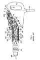
Figure 1 , the prior art demolition hammer comprises anelectric motor 2, a gear arrangement and a piston drive arrangement which are housed within ametal gear housing 5 surrounded by aplastic housing 4. A rear handle housing incorporating a rear handle 6 and atrigger switch arrangement 8 is fitted to the rear of thehousings cable guide 10 and connects the motor to an external electricity supply. When the cable is connected to the electricity supply when thetrigger switch arrangement 8 is depressed, themotor 2 is actuated to rotationally drive the armature of the motor. Aradial fan 14 is fitted at one end of the armature and a pinion is formed at the opposite end of the armature so that when the motor is actuated the armature rotatingly drives thefan 14 and the pinion. Themetal gear housing 5 is made from magnesium with steel inserts and rigidly supports the components housed within it. - The motor pinion rotatingly drives a first gear wheel of an intermediate gear arrangement which is rotatably mounted on a spindle, which spindle is mounted in an insert to the
gear housing 5. The intermediate gear has a second gear wheel which rotatingly drives a drive gear. The drive gear is non-rotatably mounted on a drive spindle mounted within thegear housing 5. Acrank plate 30 is non-rotatably mounted at the end of the drive spindle remote from the drive gear, the crank plate being formed with an eccentric bore for housing aneccentric crank pin 32. Thecrank pin 32 extends from the crank plate into a bore at the rearward end of acrank arm 34 so that the crank arm can pivot about thecrank pin 32. The opposite forward end of thecrank arm 34 is formed with a bore through which extends atrunnion pin 36 so that thecrank arm 34 can pivot about thetrunnion pin 36. Thetrunnion pin 36 is fitted to the rear of apiston 38 by fitting the ends of thetrunnion pin 36 into receiving bores formed in a pair of opposing arms which extend to the rear of thepiston 38. The piston is reciprocally mounted in cylindricalhollow spindle 40 so that it can reciprocate within the hollow spindle. An O-ring seal 42 is fitted in an annular recess formed in the periphery of thepiston 38 so as to form an airtight seal between thepiston 38 and the internal surface of thehollow spindle 40. - When the
motor 2 is actuated, the armature pinion rotatingly drives the intermediate gear arrangement via the first gear wheel and the second gear wheel of the intermediate gear arrangement rotatingly drives the drive spindle via the drive gear. The drive spindle rotatingly drives thecrank plate 30 and the crank arm arrangement comprising thecrank pin 32, thecrank arm 34 and thetrunnion pin 36 converts the rotational drive from thecrank plate 30 to a reciprocating drive to thepiston 38. In this way thepiston 38 is reciprocatingly driven back and forth along thehollow spindle 40 when the motor is actuated by a user depressing thetrigger switch 8. - The
spindle 40 is mounted inmagnesium housing 42 from the forward end until an annular rearward facing shoulder (not shown) on the exterior of the spindle butts up against a forward facing annular shoulder (not shown) formed from a set of ribs in the interior of themagnesium casing 42. The ribs enable air in the chamber surrounding thespindle 40 to circulate freely in the region betweenram 58 andbeat piece 64. An increased diameter portion on the exterior of the spindle fits closely within a reduced diameter portion on the interior of themagnesium casing 42. Rearwardly of the increased diameter portion and the reduced diameter portion an annular chamber is formed between the external surface of thespindle 40 and the internal surface of themagnesium casing 42. This chamber is open at its forward and rearward ends. At its forward end the chamber communicates via the spaces between the ribs in the magnesium casing with a volume of air between theram 58 and thebeat piece 64. At its rearward end the chamber communicates via the spaces between theribs 7 and the recess of thegear casing 5 with a volume of air in thegear casing 5. - The volume of air in the
gear casing 5 communicates with the air outside of the hammer via a narrow channel 9 and a filter 11. The air pressure within the hammer, which changes due to changes in the temperature of the hammer, is thus equalised with the air pressure outside of the hammer. The filter 11 also keeps the air within thehammer gear casing 5 relatively clean and dust free. - A
ram 58 is located within thehollow spindle 40 forwardly of thepiston 38 so that it can also reciprocate within thehollow spindle 40. An O-ring seal 60 is located in a recess formed around the periphery of theram 58 so as to form an airtight seal between theram 58 and thespindle 40. In the operating position of the ram 58 (shown in the upper half ofFigure 1 ), with the ram located behindbores 62 in the spindle, a closed air cushion is formed between the forward face of thepiston 38 and the rearward face of theram 58. Reciprocation of thepiston 38 thus reciprocatingly drives theram 58 via the closed air cushion. When the hammer enters idle mode (i.e. when the hammer bit is removed from a work piece), theram 58 moves forwardly, past thebores 62 to the position shown in the bottom half ofFigure 1 . This vents the air cushion and so theram 58 is no longer reciprocatingly driven by thepiston 38 in idle mode, as is known to persons skilled in the art. - However, known hammer drills of this type suffer from the drawback that the hammer action generates significant vibrations, which can be harmful to users of the apparatus, and can cause damage to the apparatus itself.
- It is known to reduce the effect of vibrations on users of power tools by providing absorbent material around handles of the tool, the absorbent material acting as passive vibration damping material. However, the effectiveness of such materials in reducing the transmission of vibrations to the user of the apparatus is limited.
- Active vibration reduction apparatus are known in which rotatable masses are driven about respective axes of rotation, the centres of mass of the rotatable masses being spaced from the axes of rotation such that rotation of the masses about the axes of rotation generates vibrations. By controlling the frequency of rotation of the masses, and the relative phases between the centres of mass of the masses, vibrations can be generated which can be used to counteract unwanted vibrations, for example in diesel motors. Such arrangements are disclosed in
FR 2606110 WO 88/06687 FR 2550471 EP 0840191 ,EP 0505976 andEP 0337040 . However, it has not to date been considered feasible to apply such techniques to the reduction of unwanted vibrations generated in power tools. -
DE 3427342 discloses a hammer drill in which a wobble plate drive mounted to a shaft causes reciprocating movement of a flying mass to impart impacts to a bit of the drill. The wobble plate drive has a finger engaging a piston forming part of the hammer mechanism such that rotation of a shaft to which the wobble plate is mounted causes reciprocating movement of the piston, and a countermass arranged on an opposite side of the shaft to the finger to partially counteract vibrations produced by the apparatus. However, this drill suffers from the drawback that its vibration reducing abilities and compactness are limited. -
GB 2256905 - Preferred embodiments of the present invention seek to overcome the above disadvantages of prior art power tools and to provide an alternative to the tool of
GB 2 053 768 A - According to an aspect of the present invention, there is provided a power hammer apparatus comprising the features of
claim 1. - This provides the advantage of enabling the power hammer apparatus to be made of even more compact construction.
- The apparatus may further comprise at least one projection provided on said piston cylinder for engaging cam follower means of said vibration reduction apparatus.
- At least one said projection may be provided on an internal surface of said piston cylinder.
- This provides the advantage of further assisting compact construction of the apparatus.
- The apparatus may further comprise sensor means for detecting phase and/or amplitude of vibrations produced by said vibration reduction means.
- The apparatus may further comprise control means for controlling said adjustment means in response to said sensor means.
- The apparatus may further comprise drive means for causing reciprocating motion of at least one said driveable mass and/or said piston.
- Said drive means may comprise a shaft adapted to be rotated by means of said motor, a drive member having an engaging portion for engaging at least one said driveable mass and/or said flying mass, and a counterweight offset from a position diametrically opposite said engaging portion.
- Preferred embodiments of the present invention will now be described, by way of example only and not in any limitative sense, with reference to the accompanying drawings, in which:-
-
Figure 1 is a partially cut away side view of a prior art demolition hammer; -
Figure 2 is a partially cut away perspective view of a vibration reduction apparatus of a first embodiment of the present invention; -
Figure 3 is a partially cut away view, corresponding toFigure 2 , of a vibration reduction apparatus of a second embodiment of the present invention; -
Figure 4 is a partially cut away view of a vibration reduction apparatus of a third embodiment of the present invention; -
Figures 5A and5B illustrate a simulation of performance of the vibration damping apparatus shown inFigure 4 ; -
Figure 6 shows data resulting from the simulation ofFigures 5A and5B ; -
Figure 7 is a partially exploded perspective view, corresponding toFigure 4 , of a vibration reduction apparatus of a fourth embodiment of the present invention; -
Figure 8 is a partially exploded perspective view, corresponding toFigure 4 , of a vibration reduction apparatus of a fifth embodiment of the present invention; and -
Figure 9 is a cross sectional elevation view of the apparatus ofFigure 8 . - A compact
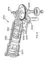
vibration reduction mechanism 901 of a first embodiment of the present invention is shown inFigure 2 . Ahammer piston 920 is driven by means ofgear plate 923 havinggear teeth 932 engaged bygear 914 ondrive shaft 911. Acam 933 is rigidly mounted togear wheel 923 and is engaged by the internal surface of acam follower plate 934.Cam follower plate 934 is connected viapin 970 tocounterweight 921, which forms part ofpiston cylinder 930 such that rotation ofcam 933 causes oscillation ofcounterweight 921 in an axial direction. - In order to deactivate
vibration reduction apparatus 901,cam follower plate 934 is displaced downwards as shown inFigure 2 to disengage cam surface ofcam follower plate 934 fromcam 933. In this way, rotation ofgear plate 923 does not cause axial movement ofcounterweight 921. - Referring to
Figure 3 , in which parts common to the embodiment ofFigure 2 are denoted by like reference numerals but increased by 100, acam follower 1034 is urged by means of a spring (not shown) into engagement withcam 1033 and is supported byyoke plate 1075 which is pivotable aboutpivot 1076 and is connected viapin 1070 withcounterweight 1021 forming part ofpiston cylinder 1030. The cam follower is biased by means ofcompression spring 1077 into engagement withcam 1033, and thevibration reduction apparatus 1001 can be deactivated by movingcounterweight 1021 to the left as shown inFigure 3 against the action ofcompression spring 1077. - A third embodiment of the invention is shown in
Figure 4 , in which parts common to the embodiment ofFigure 3 are denoted by like reference numerals but increased by 100. Acam 1133 is mounted via an aperture with abearing 1180 to apin 1181 such that rotation ofcrank 1182 causes rotation ofcam 1133 aboutrotation axis 1183. Abearing 1184 is mounted to apin 1170 oncylinder housing 1121 such that when thecylinder housing 1121 is urged in the direction of arrow D, thebearing 1184 is in contact with the peripheral surface ofcam 1133. Consequently, as thecrank 1182 is rotated to drivepiston 1120, thecylinder housing 1121, which is mounted for slideable movement relative to the tool housing (not shown), is caused to move in antiphase with thepiston 1120. Movement ofpiston 1120 incylinder 1121 causes movement of aram 1169. Abeat piece 1186 is mounted to the end ofcylinder housing 1121 by means of aspring 1187 and has an O-ring 1188 mounted to groove 1189, and a pair of O-rings 1190 on anend portion 1191 thereof. - The
cylinder 1121 is mounted to the housing in such a way that when the tool is disengaged from a workpiece (not shown), thebeat piece 1186 is separated from the end ofcylinder housing 1121 bycompression spring 1187, as a result of which theram 1169 does not come into contact with thebeat piece 1186. In this condition, thebearing 1184 is not urged into engagement withcam 1133, as a result of which thecylinder housing 1121 is not caused to oscillate. When the tool engages the workpiece, thebeat piece 1186 is pushed against the forces ofspring 1187 into contact with the end ofcylinder housing 1121, andbearing 1184 is urged into contact with the surface ofcam 1133. As a result, reciprocating motion ofpiston 1120 causes reciprocating motion ofram 1169, which contacts beatpiece 1186 at the end of its stroke, and thecylinder housing 1121 is driven in antiphase with thepiston 1120. On disengagement of the tool from the workpiece, thecylinder 1121 is pushed in the direction opposite to arrow D shown inFigure 4 , and thebeat piece 1186 is retained in a position out of engagement with the end ofcylinder housing 1121 by engagement of O-ring 1188 with the housing. As a result, the vibration damping apparatus is automatically deactivated on disengagement of the tool from the workpiece. -
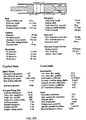
Figures 5A and5B illustrate a simulation of the performance of the vibration damping apparatus shown inFigure 4 , and the result of the simulation are shown inFigure 6 . A comparison of the vibrations generated without activation of the vibration damping apparatus (16.5m/s2) with the vibrations generated when the vibration damping apparatus is activated (6.5m/s2) shows that the arrangement shown in Figure 12 reduces vibrations by approximately 60%. - A fourth embodiment of the invention is shown in
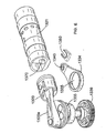
Figure 7 , in which parts common to the embodiment ofFigure 4 are denoted by like reference numerals but increased by 100. Acam follower 1234 having a generallycircular aperture 1235 at one end thereof is mounted to and surrounds acam surface 1233 and is held in position around the cam surface by means ofbearings shaft 1238 driven bygear 1239. Thegear 1239 also drivespiston 1220 viaarm 1220a. Anaperture 1240 at the end ofcam follower 1234 opposite tocircular aperture 1235 is mounted to apin 1270 on the lower surface ofcylinder 1221, such that rotation ofshaft 1238 to drivepiston 1220 viaarm 1220a also causes rotation ofcam surface 1233, which in turn causes reciprocating motion ofaperture 1240 andpin 1270. This in turn results in linear reciprocating motion ofcylinder 1221 in anti phase with the reciprocating motion ofpiston 1220. - In the arrangement of
Figure 7 , thecam follower 1234 is not disengaged from thecam surface 1233 orpin 1270 when the tool bit (not shown) is disengaged from a workpiece (not shown), as a result of which the vibration reduction mechanism is always switched on, and vibrations caused by the vibration reduction mechanism are tolerated. However, the embodiment ofFigure 7 has the advantage of making maximum use of existing parts and simplifying the construction of the apparatus, as well as making the apparatus of compact construction. - Referring now to
Figures 8 and9 , in which parts common to the embodiment ofFigure 7 are denoted by like reference numerals but increased by 100, a fifth embodiment of the invention differs from the embodiment of Figure 15 in thatcam follower 1334 having generallycircular aperture 1335 is mounted to apin 1370 provided on an internal surface of thepiston cylinder 1321. As can be best seen in Figure 17, thepin 1370 is arranged insidepiston cylinder 1321, as a result of which thepin 1370 sits behindpiston 1320 in the rearmost position of thepiston 1320. This enables the apparatus to be of considerably more compact construction than other embodiments. - An alternative arrangement of the
cam follower 1334 is also shown inFigure 8 , in which theaperture 1340 at the forward end of thecam follower 1334 is replaced by a generallyU-shaped notch 1350 for engaging thepin 1370 provided in thepiston cylinder 1321. Thenotch 1350 enables thepin 1370 to be disengaged from thecam follower 1334 by means of biasing means (not shown) when the tool is disengaged from a workpiece (not shown) in a manner similar to the embodiment ofFigure 4 , to deactivate the vibration reducing apparatus. When the tool bit is pushed into engagement with a workpiece, thecam follower 1334 is pushed into engagement with thepin 1370, so that thepin 1370 is received in thenotch 1350 throughout the entire path of theaperture 1340. - It will be appreciated by persons skilled in the art that the above embodiments have been described by way of example only and not in any limitative sense, and that various alterations and modifications are possible without departure from the scope of the invention as defined by the appended claims.
Claims (5)
- A power hammer apparatus comprising:-a housing (4);a motor (2) arranged in the housing (4);a piston cylinder (930) defining a bore;a piston (920) adapted to be caused by said motor to execute reciprocating motion in said bore;a flying mass (58) arranged in the bore such that said reciprocating motion of said piston in said bore in use causes reciprocating motion of said flying mass relative to said housing to impart impacts to a working member of the power hammer apparatus; andvibration reduction means (921; 1021; 1121; 1221; 1321) in the housing, the vibration reduction means comprising at least one drivable mass adapted to be caused by the motor to execute reciprocating motion to at least partially cancel vibration of said housing (4) caused by reciprocating motion of the flying mass relative to the housing (4);characterised in that at least one said drivable mass forms at least part of said cylinder (930; 1030; 1121; 1221; 1321).
- A power hammer apparatus according to claim 1, further comprising at least one projection (970) on said piston cylinder for engaging cam follower means (934) of said vibration reduction apparatus.
- A power hammer apparatus according to claim 2, wherein at least one said projection (1370) is provided on an internal surface of said piston cylinder (1321).
- A power hammer apparatus according to any one of the preceding claims, further comprising drive means (911, 923, 934) for causing reciprocating motion of at least one said driveable mass and/or said piston.
- A power hammer apparatus according to claim 4, wherein said drive means comprises a shaft (911) adapted to be rotated by means of said motor, a drive member (923) having an engaging portion for engaging at least one said driveable mass and/or said flying mass, and a countermass (921) offset from a position diametrically opposite said engaging portion.
Priority Applications (1)
| Application Number | Priority Date | Filing Date | Title |
|---|---|---|---|
| EP07102225.5A EP1779980A3 (en) | 2003-03-21 | 2004-03-19 | Vibration reduction apparatus for power tool and power tool incorporating such apparatus |
Applications Claiming Priority (3)
| Application Number | Priority Date | Filing Date | Title |
|---|---|---|---|
| GB0306525A GB2399615B (en) | 2003-03-21 | 2003-03-21 | Vibration reduction apparatus for power tool and power tool incorporating such apparatus |
| GB0323885A GB0323885D0 (en) | 2003-10-11 | 2003-10-11 | Vibration reduction apparatus for power tool and power tool incorporating such apparatus |
| EP04721875A EP1606082B1 (en) | 2003-03-21 | 2004-03-19 | Power tool with vibration reduction means |
Related Parent Applications (1)
| Application Number | Title | Priority Date | Filing Date |
|---|---|---|---|
| EP04721875A Division EP1606082B1 (en) | 2003-03-21 | 2004-03-19 | Power tool with vibration reduction means |
Related Child Applications (2)
| Application Number | Title | Priority Date | Filing Date |
|---|---|---|---|
| EP07102225.5A Division-Into EP1779980A3 (en) | 2003-03-21 | 2004-03-19 | Vibration reduction apparatus for power tool and power tool incorporating such apparatus |
| EP07102225.5A Division EP1779980A3 (en) | 2003-03-21 | 2004-03-19 | Vibration reduction apparatus for power tool and power tool incorporating such apparatus |
Publications (2)
| Publication Number | Publication Date |
|---|---|
| EP1710052A1 EP1710052A1 (en) | 2006-10-11 |
| EP1710052B1 true EP1710052B1 (en) | 2014-11-19 |
Family
ID=33031415
Family Applications (7)
| Application Number | Title | Priority Date | Filing Date |
|---|---|---|---|
| EP08103158.5A Withdrawn EP1932627A3 (en) | 2003-03-21 | 2004-03-19 | Vibration reduction apparatus for power tool and power tool incorporating such apparatus |
| EP07109072A Expired - Lifetime EP1818141B1 (en) | 2003-03-21 | 2004-03-19 | Vibration reduction apparatus for power tool and power tool incorporating such apparatus |
| EP07102225.5A Withdrawn EP1779980A3 (en) | 2003-03-21 | 2004-03-19 | Vibration reduction apparatus for power tool and power tool incorporating such apparatus |
| EP08103157.7A Expired - Lifetime EP1932626B1 (en) | 2003-03-21 | 2004-03-19 | Vibration reduction apparatus for power tool and power tool incorporating such apparatus |
| EP09169221.0A Expired - Lifetime EP2119536B1 (en) | 2003-03-21 | 2004-03-19 | Power tool incorporating vibration reduction apparatus |
| EP06117029.6A Expired - Lifetime EP1710052B1 (en) | 2003-03-21 | 2004-03-19 | Power hammer comprising a vibration reduction means |
| EP04721875A Expired - Lifetime EP1606082B1 (en) | 2003-03-21 | 2004-03-19 | Power tool with vibration reduction means |
Family Applications Before (5)
| Application Number | Title | Priority Date | Filing Date |
|---|---|---|---|
| EP08103158.5A Withdrawn EP1932627A3 (en) | 2003-03-21 | 2004-03-19 | Vibration reduction apparatus for power tool and power tool incorporating such apparatus |
| EP07109072A Expired - Lifetime EP1818141B1 (en) | 2003-03-21 | 2004-03-19 | Vibration reduction apparatus for power tool and power tool incorporating such apparatus |
| EP07102225.5A Withdrawn EP1779980A3 (en) | 2003-03-21 | 2004-03-19 | Vibration reduction apparatus for power tool and power tool incorporating such apparatus |
| EP08103157.7A Expired - Lifetime EP1932626B1 (en) | 2003-03-21 | 2004-03-19 | Vibration reduction apparatus for power tool and power tool incorporating such apparatus |
| EP09169221.0A Expired - Lifetime EP2119536B1 (en) | 2003-03-21 | 2004-03-19 | Power tool incorporating vibration reduction apparatus |
Family Applications After (1)
| Application Number | Title | Priority Date | Filing Date |
|---|---|---|---|
| EP04721875A Expired - Lifetime EP1606082B1 (en) | 2003-03-21 | 2004-03-19 | Power tool with vibration reduction means |
Country Status (9)
| Country | Link |
|---|---|
| US (4) | US7331407B2 (en) |
| EP (7) | EP1932627A3 (en) |
| JP (7) | JP4662924B2 (en) |
| CN (1) | CN101898352B (en) |
| AT (2) | ATE466696T1 (en) |
| AU (2) | AU2004222098B2 (en) |
| DE (2) | DE202004021825U1 (en) |
| DK (1) | DK1818141T3 (en) |
| WO (1) | WO2004082897A1 (en) |
Families Citing this family (108)
| Publication number | Priority date | Publication date | Assignee | Title |
|---|---|---|---|---|
| EP1932627A3 (en) * | 2003-03-21 | 2014-08-13 | Black & Decker, Inc. | Vibration reduction apparatus for power tool and power tool incorporating such apparatus |
| WO2005105386A1 (en) * | 2004-04-30 | 2005-11-10 | Makita Corporation | Working tool |
| JP4742613B2 (en) * | 2005-02-24 | 2011-08-10 | マックス株式会社 | Drill tool |
| US8261851B2 (en) | 2005-04-11 | 2012-09-11 | Makita Corporation | Electric hammer |
| EP1870209B1 (en) * | 2005-04-11 | 2016-12-21 | Makita Corporation | Electric hammer |
| DE102005021734A1 (en) * | 2005-05-11 | 2006-11-16 | Robert Bosch Gmbh | Power tool |
| US7866411B2 (en) * | 2005-12-20 | 2011-01-11 | Dentatus Ab | Vibration dampened hand-held power tool |
| JP2007175839A (en) * | 2005-12-28 | 2007-07-12 | Hitachi Koki Co Ltd | Striking tool |
| JP5041575B2 (en) * | 2006-03-07 | 2012-10-03 | 日立工機株式会社 | Impact tool |
| DE102006000279A1 (en) * | 2006-06-08 | 2007-12-13 | Hilti Ag | Hand tool with crank-driven air spring impact mechanism |
| US7413026B2 (en) | 2006-07-01 | 2008-08-19 | Black & Decker Inc. | Lubricant system for powered hammer |
| EP1872914B1 (en) * | 2006-07-01 | 2010-09-22 | Black & Decker, Inc. | A Pavement Breaker |
| US7401661B2 (en) * | 2006-07-01 | 2008-07-22 | Black & Decker Inc. | Lubricant pump for powered hammer |
| AU2007202963A1 (en) | 2006-07-01 | 2008-01-17 | Black & Decker, Inc. | A beat piece wear indicator for a hammer drill |
| US20080006419A1 (en) * | 2006-07-01 | 2008-01-10 | Black & Decker Inc. | Tool holder connector for powered hammer |
| EP1872913B1 (en) * | 2006-07-01 | 2015-08-19 | Black & Decker, Inc. | A tool holder for a hammer apparatus |
| JP4756474B2 (en) | 2006-07-20 | 2011-08-24 | 日立工機株式会社 | Electric tool |
| JP4863942B2 (en) * | 2006-08-24 | 2012-01-25 | 株式会社マキタ | Impact tool |
| DE102006053105A1 (en) * | 2006-11-10 | 2008-05-15 | Robert Bosch Gmbh | Hand tools percussion device |
| DE102006054288A1 (en) * | 2006-11-17 | 2008-05-21 | A & M Electric Tools Gmbh | Rotary Hammer |
| DE102006059076A1 (en) * | 2006-12-14 | 2008-06-19 | Robert Bosch Gmbh | Schlagwerk an electric hand tool machine |
| DE102006060320A1 (en) * | 2006-12-20 | 2008-06-26 | Robert Bosch Gmbh | Schlagwerk for a hand tool |
| DE102007000057B4 (en) * | 2007-01-31 | 2010-07-08 | Hilti Aktiengesellschaft | Vibration damper for hand tool |
| DE102007000059A1 (en) | 2007-01-31 | 2008-09-18 | Hilti Aktiengesellschaft | Hand tool with vibration absorber |
| US7878265B2 (en) * | 2007-02-06 | 2011-02-01 | Makita Corporation | Impact power tool |
| US8549762B2 (en) * | 2007-02-13 | 2013-10-08 | Robert Bosch Gmbh | Linkage drive mechanism for a reciprocating tool |
| US7814666B2 (en) * | 2007-02-13 | 2010-10-19 | Robert Bosch Gmbh | Linkage drive mechanism for a reciprocating tool |
| US7832498B2 (en) * | 2007-06-15 | 2010-11-16 | Makita Corporation | Impact tool |
| DE102007000393A1 (en) * | 2007-07-19 | 2009-01-22 | Hilti Aktiengesellschaft | Hand tool with pneumatic percussion |
| JP5015697B2 (en) * | 2007-08-30 | 2012-08-29 | 株式会社マキタ | Impact tool |
| DE102007042721A1 (en) * | 2007-09-07 | 2009-03-12 | Robert Bosch Gmbh | Hand tool with a vibration-dampened by a compensating means handle |
| DE102007055843A1 (en) | 2007-12-17 | 2009-06-25 | Hilti Aktiengesellschaft | Hand tool with vibration compensator |
| US8196674B2 (en) * | 2008-03-05 | 2012-06-12 | Makita Corporation | Impact tool |
| JP5202997B2 (en) * | 2008-03-05 | 2013-06-05 | 株式会社マキタ | Work tools |
| WO2009111747A2 (en) * | 2008-03-07 | 2009-09-11 | Milwaukee Electric Tool Corporation | Portable battery-powered reciprocating saw |
| US8407902B2 (en) | 2008-03-07 | 2013-04-02 | Milwaukee Electric Tool Corporation | Reciprocating power tool having a counterbalance device |
| DE102008000677A1 (en) * | 2008-03-14 | 2009-09-17 | Robert Bosch Gmbh | Hand tool for impact driven tools |
| DE102008000687A1 (en) * | 2008-03-14 | 2009-09-17 | Robert Bosch Gmbh | Hand tool for impact driven tools |
| KR100914641B1 (en) * | 2008-04-10 | 2009-09-02 | 이재민 | Nail holding and hitting device |
| WO2009156931A2 (en) * | 2008-06-26 | 2009-12-30 | Koninklijke Philips Electronics, N.V. | Method and system for fast precise path planning |
| JP5290666B2 (en) * | 2008-08-29 | 2013-09-18 | 株式会社マキタ | Impact tool |
| DE102008044219A1 (en) * | 2008-12-01 | 2010-06-02 | Robert Bosch Gmbh | Hand machine tool device |
| DE102008054873A1 (en) * | 2008-12-18 | 2010-07-01 | Robert Bosch Gmbh | Hand tool with counter-oscillator |
| ATE527083T1 (en) | 2009-01-30 | 2011-10-15 | Hilti Ag | PNEUMATIC IMPACT MECHANISM |
| DE102009008190A1 (en) | 2009-01-30 | 2010-08-05 | Hilti Aktiengesellschaft | Pneumatic percussion |
| DE102009008189A1 (en) | 2009-01-30 | 2010-08-05 | Hilti Aktiengesellschaft | Pneumatic impact mechanism and control method |
| DE102009001590A1 (en) | 2009-03-17 | 2010-09-23 | Robert Bosch Gmbh | Hand tool with a counter-oscillator |
| JP5361504B2 (en) * | 2009-04-10 | 2013-12-04 | 株式会社マキタ | Impact tool |
| DE102009019081A1 (en) * | 2009-04-22 | 2010-11-11 | Biax-Maschinen Gmbh | Hand tool with a linear vibration drive |
| US8087472B2 (en) * | 2009-07-31 | 2012-01-03 | Black & Decker Inc. | Vibration dampening system for a power tool and in particular for a powered hammer |
| DE102009044938A1 (en) | 2009-09-24 | 2011-03-31 | Robert Bosch Gmbh | Power tool with a striking mechanism assembly and a balancing mass to compensate for vibrations of the power tool |
| DE102009044934A1 (en) | 2009-09-24 | 2011-03-31 | Robert Bosch Gmbh | Connecting rod drive with additional oscillator |
| DE102009044941A1 (en) | 2009-09-24 | 2011-03-31 | Robert Bosch Gmbh | Counteroscillator, which is providable to compensate for housing vibrations of a power tool in this |
| JP2011131455A (en) | 2009-12-24 | 2011-07-07 | Du Pont-Toray Co Ltd | Method for producing polyimide molded body |
| CN101758486B (en) * | 2010-01-21 | 2011-09-28 | 浙江海王电器有限公司 | Light single-button multifunctional electric hammer |
| JP5496812B2 (en) * | 2010-08-03 | 2014-05-21 | 株式会社マキタ | Work tools |
| JP5535051B2 (en) * | 2010-11-22 | 2014-07-02 | 株式会社マキタ | Power tools |
| US9033301B1 (en) | 2011-04-26 | 2015-05-19 | The Boeing Company | Vibration reduction system using an extended washer |
| JP5767511B2 (en) * | 2011-06-01 | 2015-08-19 | 株式会社マキタ | Reciprocating work tool |
| DE102011078628A1 (en) * | 2011-07-05 | 2013-01-10 | Robert Bosch Gmbh | chlagwerkvorrichtung |
| US9156152B2 (en) * | 2011-08-31 | 2015-10-13 | Makita Corporation | Impact tool having counter weight that reduces vibration |
| JP5790466B2 (en) * | 2011-12-08 | 2015-10-07 | トヨタ自動車株式会社 | Control device for hybrid vehicle |
| DE102012203757A1 (en) * | 2012-03-09 | 2013-09-12 | Robert Bosch Gmbh | Hand machine tool device |
| JP5783498B2 (en) * | 2012-03-22 | 2015-09-24 | 日立工機株式会社 | Electric tool |
| AT513094B1 (en) * | 2012-03-28 | 2015-01-15 | Tech Universität Wien | Device, in particular chip tool |
| DE102012206445A1 (en) * | 2012-04-19 | 2013-10-24 | Hilti Aktiengesellschaft | machine tool |
| JP6124433B2 (en) * | 2012-09-10 | 2017-05-10 | 株式会社マンダム | Method for evaluating antiseptic strength of sheet |
| KR101710530B1 (en) * | 2012-12-10 | 2017-02-27 | 쿠오-칭 루 | Anti-impact force apparatus |
| US9981372B2 (en) * | 2012-12-31 | 2018-05-29 | Robert Bosch Tool Corporation | Reciprocating tool with fluid driven counterweight |
| US9416514B2 (en) * | 2013-01-29 | 2016-08-16 | Danuser Llc | Post driver with limited movement floating post anvil |
| EP2857149A1 (en) * | 2013-10-03 | 2015-04-08 | HILTI Aktiengesellschaft | Manual tool machine |
| DE102013221108A1 (en) * | 2013-10-17 | 2015-05-07 | Robert Bosch Gmbh | Machine tool device |
| JP2015199167A (en) * | 2014-04-08 | 2015-11-12 | 株式会社マキタ | Electric power tool |
| US11346219B2 (en) | 2014-04-24 | 2022-05-31 | Aquarius Engines (A.M.) Ltd. | Engine with work stroke and gas exchange through piston rod |
| US11008864B2 (en) | 2014-04-24 | 2021-05-18 | Aquarius Engines (A.M.) Ltd. | Engine with work stroke and gas exchange through piston rod |
| JP6441588B2 (en) * | 2014-05-16 | 2018-12-19 | 株式会社マキタ | Impact tool |
| JP6345045B2 (en) * | 2014-09-05 | 2018-06-20 | 株式会社マキタ | Impact tool |
| JP6308985B2 (en) * | 2014-10-28 | 2018-04-11 | 黒田精工株式会社 | Work table device |
| JP6510250B2 (en) * | 2015-01-29 | 2019-05-08 | 株式会社マキタ | Work tools |
| WO2017009717A1 (en) | 2015-07-15 | 2017-01-19 | Aquarius Engines (A.M.) Ltd. | Free piston engine |
| US9872443B2 (en) * | 2015-09-24 | 2018-01-23 | Thomas B. Burch | Apparatus, system and method for delivering treatment fluid to vegetation |
| WO2017068427A1 (en) * | 2015-10-20 | 2017-04-27 | Shaul Yaakoby | Vibration prevention in a linear actuator |
| ITUB20160572A1 (en) * | 2016-01-19 | 2017-07-19 | Ciro Tarallo | DRILL HAMMER EXCAVATOR PERCUSSION WITH ELECTROMAGNETIC REPULSION |
| KR101673542B1 (en) * | 2016-05-12 | 2016-11-09 | 정은경 | Crops harvested Combine driving pile machine |
| KR101650906B1 (en) * | 2016-05-12 | 2016-08-24 | 주식회사 가우스 | Single acting driving pile machine |
| TWI604141B (en) * | 2016-11-07 | 2017-11-01 | 財團法人工業技術研究院 | Shock absorber and semi-active type shock absorbing method |
| US20180264566A1 (en) * | 2017-03-20 | 2018-09-20 | Milwaukee Electric Tool Corporation | Reciprocating saw |
| WO2018221105A1 (en) * | 2017-05-31 | 2018-12-06 | 工機ホールディングス株式会社 | Reciprocating tool |
| JP6987599B2 (en) * | 2017-10-20 | 2022-01-05 | 株式会社マキタ | Strike tool |
| EP3697574A1 (en) | 2017-10-20 | 2020-08-26 | Milwaukee Electric Tool Corporation | Percussion tool |
| CN107891532B (en) * | 2017-10-26 | 2019-05-10 | 上海三航奔腾海洋工程有限公司 | A kind of convenient wall drilling device of construction |
| CN111315537B (en) * | 2017-10-31 | 2022-11-15 | 工机控股株式会社 | Driving machine |
| US11059155B2 (en) | 2018-01-26 | 2021-07-13 | Milwaukee Electric Tool Corporation | Percussion tool |
| CN215617869U (en) | 2018-04-04 | 2022-01-25 | 米沃奇电动工具公司 | Rotary hammer suitable for applying axial impact to tool head |
| CN108942805A (en) * | 2018-08-01 | 2018-12-07 | 苏州穹力机械科技有限公司 | Simply pound hammer machine |
| US10882124B2 (en) | 2018-09-07 | 2021-01-05 | Advanced Machine & Engineering Co. | Saw blade stabilizer and method |
| US10641166B1 (en) | 2018-12-03 | 2020-05-05 | Aquarius Engines (A.M.) Ltd. | Piston rod and free piston engine |
| EP4250541A3 (en) | 2019-04-24 | 2024-04-10 | Black & Decker Inc. | Outer rotor brushless motor having an axial fan |
| US11229963B2 (en) * | 2019-06-24 | 2022-01-25 | Black & Decker Inc. | Force and moment canceling reciprocating mechanism and power tool having same |
| US11453093B2 (en) | 2019-06-24 | 2022-09-27 | Black & Decker Inc. | Reciprocating tool having planetary gear assembly and counterweighting assembly |
| US11008959B2 (en) | 2019-06-28 | 2021-05-18 | Aquarius Engines Central Europe Sp. z o.o. | System and method for controlling engine using reference point |
| NL2023723B1 (en) * | 2019-08-28 | 2021-05-11 | Univ Delft Tech | Shaker for gentle driving of piles |
| GB201916665D0 (en) * | 2019-11-15 | 2020-01-01 | Black & Decker Inc | Piston |
| EP4076815A4 (en) * | 2019-12-20 | 2023-12-27 | Milwaukee Electric Tool Corporation | Reciprocating saw |
| US11642769B2 (en) * | 2021-02-22 | 2023-05-09 | Makita Corporation | Power tool having a hammer mechanism |
| US20220354052A1 (en) | 2021-05-05 | 2022-11-10 | Black & Decker Inc. | Outer rotor brushless motor and planetary gear assembly for power tool |
| US11958121B2 (en) | 2022-03-04 | 2024-04-16 | Black & Decker Inc. | Reciprocating tool having orbit function |
| US11839964B2 (en) | 2022-03-09 | 2023-12-12 | Black & Decker Inc. | Counterbalancing mechanism and power tool having same |
Family Cites Families (83)
| Publication number | Priority date | Publication date | Assignee | Title |
|---|---|---|---|---|
| US658284A (en) | 1899-08-11 | 1900-09-18 | Albert Schoenhut | Toy piano. |
| US672320A (en) * | 1899-12-13 | 1901-04-16 | Robert Edgar Ford | Counterbalance. |
| US1015732A (en) * | 1909-10-05 | 1912-01-23 | Arthur George Grice | Percussive tool. |
| FR474902A (en) * | 1913-07-11 | 1915-03-26 | Societe Francaise D Exploitation Des Appareils Koe | Oil and liquid fuel heater |
| DE493098C (en) * | 1927-12-11 | 1930-03-05 | Arthur Wolschke | Spring hammer with revolving drive |
| US1802987A (en) | 1928-09-18 | 1931-04-28 | Ingersoll Rand Co | Rock drill |
| US2400650A (en) * | 1941-09-02 | 1946-05-21 | Mechanical Res Corp | Vibration apparatus |
| US2428924A (en) * | 1944-07-24 | 1947-10-14 | Minneapolis Moline Power Co | Counterbalance mechanism |
| GB658284A (en) * | 1947-07-24 | 1951-10-03 | Henry Kielholz | Improvements in or relating to striking hammers with mechanical drive |
| US2632331A (en) | 1949-05-12 | 1953-03-24 | Pinazza Giosue | Motion converting means |
| US2764188A (en) * | 1953-10-07 | 1956-09-25 | Simon J Hoffman | Reciprocating saw with reversible blade |
| US2875731A (en) * | 1956-03-23 | 1959-03-03 | Buckeye Steel Castings Co | Vibration absorbers for reciprocating tools |
| US3028841A (en) * | 1958-06-18 | 1962-04-10 | Leavell Charles | Vibration elimination |
| US3024770A (en) * | 1959-09-29 | 1962-03-13 | Dunlop Rubber Co | Ram damping device |
| US3023628A (en) * | 1960-08-01 | 1962-03-06 | Leander J Heppner | Impact tool |
| GB1020436A (en) | 1963-01-30 | 1966-02-16 | Societe D'etudes Et D'applications Industrielles, Commerciales Et Immobiliers "Inter-Technique" | |
| DE1281970B (en) | 1964-06-25 | 1968-10-31 | Reichsbahn Vertreten Durch Den | Vibration damper for hammer |
| CH495515A (en) | 1968-08-30 | 1970-08-31 | Sulzer Ag | Damper for bodies that can vibrate in three different axial directions |
| FR2132916A5 (en) * | 1971-04-01 | 1972-11-24 | Peugeot Aciers Et Outillage | |
| US3845827A (en) | 1971-08-05 | 1974-11-05 | Stihl Maschf Andreas | Portable implement,especially motor chain saw |
| JPS516583U (en) * | 1974-07-02 | 1976-01-17 | ||
| DE2653064A1 (en) * | 1976-11-23 | 1978-05-24 | Gerhard Dipl Ing Vonnemann | Multi impact member rock drill drive - has members crank driven with debris removal system operated by same drive |
| US4346768A (en) * | 1977-05-12 | 1982-08-31 | Ross Frederick W | Impact device with sinusoidal rotary-to-reciprocative converter |
| DE2844086A1 (en) * | 1978-10-10 | 1980-04-30 | Bosch Gmbh Robert | HAND MACHINE, IN PARTICULAR HAMMER |
| CH638587A5 (en) * | 1979-02-12 | 1983-09-30 | Uster Spindel Motoren Maschf | HAMMER. |
| DE2912280A1 (en) * | 1979-03-28 | 1980-10-09 | Rilco Maschf | PUNCHING OR PAMPING DEVICE |
| JPS6033636B2 (en) * | 1979-07-04 | 1985-08-03 | 日立工機株式会社 | electric hammer |
| EP0025153B1 (en) | 1979-08-31 | 1983-08-31 | Black & Decker Inc. | Portable tool such as a rotary hammer or the like |
| CH642433A5 (en) | 1979-10-23 | 1984-04-13 | Fritz Knoll | DEVICE FOR ABSORBING MOTION ENERGY. |
| US4279091A (en) | 1979-12-03 | 1981-07-21 | Edwards Jesse B | Firearm recoil reducer |
| SE8001824L (en) | 1980-03-07 | 1981-09-08 | Holzman Siv Anna Eleonora | REKYLDEMPARE |
| WO1981003518A1 (en) | 1980-06-02 | 1981-12-10 | Caterpillar Tractor Co | Vibration isolator device for a percussion tool |
| EP0052507B1 (en) * | 1980-11-18 | 1985-02-13 | Black & Decker Inc. | Percussive drills |
| DE3122979A1 (en) * | 1981-06-10 | 1983-01-05 | Hilti AG, 9494 Schaan | DRILLING OR CHISEL HAMMER |
| GB2129733A (en) * | 1982-10-27 | 1984-05-23 | Jean Walton | More-vibration-free concrete breakers and percussion drills |
| SE8207351L (en) | 1982-12-22 | 1984-06-23 | Peter Johan Torsten Tornqvist | SET AND DEVICE TO BALANCE A FRONT AND RETURN MOVEMENT |
| DE3304916A1 (en) * | 1983-02-12 | 1984-08-16 | Robert Bosch Gmbh, 7000 Stuttgart | DRILLING HAMMER |
| SU1138310A1 (en) * | 1983-05-20 | 1985-02-07 | Всесоюзный Научно-Исследовательский И Проектно-Конструкторский Институт Механизированного И Ручного Строительно-Монтажного Инструмента,Вибраторов И Строительно-Отделочных Машин | Air-spring percussive tool |
| FR2550471B1 (en) | 1983-08-08 | 1987-06-19 | Strasbourg Ste Indle Forges | VIBRATOR FOR ADJUSTING THE PHASE IN A VIBRATING APPARATUS |
| JPS6094281A (en) * | 1983-10-28 | 1985-05-27 | 日立工機株式会社 | Vibration reducer for striking tool |
| JPS60237239A (en) * | 1984-05-11 | 1985-11-26 | Mitsubishi Heavy Ind Ltd | Vibration generator |
| DE3427342A1 (en) | 1984-07-25 | 1986-01-30 | Robert Bosch Gmbh, 7000 Stuttgart | Hammer drill |
| FR2606110A1 (en) | 1986-11-05 | 1988-05-06 | Alsthom | Device for compensating for the vibrational force of vibrational torque to which a body is subjected |
| EP0337040A1 (en) | 1988-04-14 | 1989-10-18 | Gec Alsthom Sa | Device for compensating a vibrational force or a vibrational torque created by a body |
| DK155544C (en) | 1987-03-02 | 1989-10-09 | Smidth & Co As F L | VICTION COMPENSATOR |
| DE8708167U1 (en) * | 1987-06-10 | 1988-10-13 | Robert Bosch Gmbh, 7000 Stuttgart, De | |
| JP2683910B2 (en) * | 1988-04-28 | 1997-12-03 | 株式会社芝浦製作所 | Vibrating tool |
| SU1617139A1 (en) * | 1988-08-09 | 1990-12-30 | Московское Научно-Производственное Объединение По Механизированному Строительному Инструменту И Отделочным Машинам | Compression-vacuum percussive machine |
| US4991644A (en) * | 1989-07-12 | 1991-02-12 | Tufts University | Engine preheating process and system |
| US4984640A (en) * | 1990-02-26 | 1991-01-15 | Gillan Leland E | Power post driver and hammer |
| US5025562A (en) | 1990-03-01 | 1991-06-25 | Milwaukee Electric Tool Corporation | Counterbalanced reciprocating mechanism |
| JPH04107342A (en) * | 1990-08-29 | 1992-04-08 | Toyo Seikan Kaisha Ltd | Dynamic balancer device |
| FR2674594B1 (en) | 1991-03-28 | 1993-06-04 | Acb | DEVICE FOR COMPENSATING A VIBRATORY FORCE OR A VIBRATORY TORQUE SUFFERED BY A BODY. |
| IL105743A0 (en) * | 1992-06-11 | 1993-09-22 | Dov Shilkrut | Penetrating tool system |
| US5355964A (en) * | 1993-07-12 | 1994-10-18 | White John L | Pile driving and/or pile pulling vibratory assembly with counterweights |
| JP3154597B2 (en) * | 1993-08-27 | 2001-04-09 | 三菱重工業株式会社 | Active vibration suppression device using unbalanced shaker |
| US5511533A (en) | 1994-02-03 | 1996-04-30 | Waller; Charles O. | Adjustable hydraulic stabilizer for a bow |
| DE29505125U1 (en) | 1995-03-25 | 1995-06-29 | Irmer & Elze Maschinenfabrik G | Vibration-dampened hand tool |
| US6007958A (en) | 1995-06-27 | 1999-12-28 | Mitsubishi Rayon Company Ltd. | Polyester resin for full color toner |
| JP3292969B2 (en) * | 1995-08-18 | 2002-06-17 | 株式会社マキタ | Hammer drill |
| US5555626A (en) * | 1995-11-27 | 1996-09-17 | S-B Power Tool Company | Reciprocating drive mechanism |
| US5825663A (en) | 1996-11-04 | 1998-10-20 | Gec-Marconi Aerospace Inc. | Vibration control system |
| DE19646622B4 (en) * | 1996-11-12 | 2004-07-01 | Wacker Construction Equipment Ag | Tool that can be carried in one movement |
| DE19717712A1 (en) * | 1997-04-18 | 1998-10-22 | Black & Decker Inc | Hammer drill |
| DE19746447C2 (en) | 1997-10-21 | 2002-11-07 | Biax Maschinen Gmbh Steckborn | Hand tool with a linear vibratory drive |
| AU751720B2 (en) * | 1998-09-18 | 2002-08-22 | Stanley Fastening Systems, L.P. | Multi-stroke fastening device |
| DE19851888C1 (en) | 1998-11-11 | 2000-07-13 | Metabowerke Kg | Hammer drill |
| DE19933972A1 (en) * | 1999-07-20 | 2001-01-25 | Bosch Gmbh Robert | Hammer drill or hammer |
| DE10052447B4 (en) * | 2000-10-23 | 2008-12-18 | Hilti Aktiengesellschaft | Beating electric hand tool with vibration reduction on the handle |
| GB0109747D0 (en) * | 2001-04-20 | 2001-06-13 | Black & Decker Inc | Hammer |
| DE10142569A1 (en) * | 2001-08-30 | 2003-03-27 | Bosch Gmbh Robert | Manual tool machine has beater w ith piston connected to drive unit and transmission element, with rotarily driven curved element and piston rod |
| US20030051352A1 (en) * | 2001-09-20 | 2003-03-20 | One World Technologies, Inc. | Reciprocating saw with flush blade |
| EP1415768A1 (en) | 2002-10-31 | 2004-05-06 | Atlas Copco Electric Tools GmbH | Oscillation damper |
| JP4275930B2 (en) | 2002-11-07 | 2009-06-10 | 株式会社マキタ | Work tools |
| JP4195818B2 (en) * | 2003-01-16 | 2008-12-17 | 株式会社マキタ | Electric hammer |
| US6763987B1 (en) * | 2003-01-31 | 2004-07-20 | Glen Richard Eberle | Backpack with incorporated gun scabbard |
| EP1932627A3 (en) * | 2003-03-21 | 2014-08-13 | Black & Decker, Inc. | Vibration reduction apparatus for power tool and power tool incorporating such apparatus |
| DE602004026134D1 (en) | 2003-04-01 | 2010-05-06 | Makita Corp | power tool |
| DE602004026243D1 (en) * | 2003-05-09 | 2010-05-12 | Makita Corp | power tool |
| DE102004012820B3 (en) * | 2004-03-16 | 2005-11-17 | Wacker Construction Equipment Ag | Wobble drive |
| EP1615086B1 (en) * | 2004-07-08 | 2011-12-07 | Asulab S.A. | Method and device to display a cycle of images of the moon, notably in a watch |
| US7383895B2 (en) * | 2005-08-19 | 2008-06-10 | Makita Corporation | Impact power tool |
| JP4341602B2 (en) * | 2005-09-28 | 2009-10-07 | 日立工機株式会社 | Impact tool |
-
2004
- 2004-03-19 EP EP08103158.5A patent/EP1932627A3/en not_active Withdrawn
- 2004-03-19 DE DE202004021825U patent/DE202004021825U1/en not_active Expired - Lifetime
- 2004-03-19 EP EP07109072A patent/EP1818141B1/en not_active Expired - Lifetime
- 2004-03-19 US US10/556,971 patent/US7331407B2/en not_active Expired - Lifetime
- 2004-03-19 JP JP2006504759A patent/JP4662924B2/en not_active Expired - Fee Related
- 2004-03-19 AT AT04721875T patent/ATE466696T1/en not_active IP Right Cessation
- 2004-03-19 AU AU2004222098A patent/AU2004222098B2/en not_active Ceased
- 2004-03-19 EP EP07102225.5A patent/EP1779980A3/en not_active Withdrawn
- 2004-03-19 CN CN2010102265738A patent/CN101898352B/en not_active Expired - Fee Related
- 2004-03-19 EP EP08103157.7A patent/EP1932626B1/en not_active Expired - Lifetime
- 2004-03-19 EP EP09169221.0A patent/EP2119536B1/en not_active Expired - Lifetime
- 2004-03-19 DK DK07109072.4T patent/DK1818141T3/en active
- 2004-03-19 EP EP06117029.6A patent/EP1710052B1/en not_active Expired - Lifetime
- 2004-03-19 AT AT07109072T patent/ATE467487T1/en active
- 2004-03-19 DE DE602004027011T patent/DE602004027011D1/en not_active Expired - Lifetime
- 2004-03-19 WO PCT/EP2004/002914 patent/WO2004082897A1/en active Application Filing
- 2004-03-19 EP EP04721875A patent/EP1606082B1/en not_active Expired - Lifetime
-
2007
- 2007-12-28 US US11/966,542 patent/US7445056B2/en not_active Expired - Lifetime
-
2008
- 2008-04-11 US US12/082,652 patent/US7533736B2/en not_active Expired - Fee Related
- 2008-04-11 US US12/082,650 patent/US7562721B2/en not_active Expired - Fee Related
-
2009
- 2009-09-17 JP JP2009216078A patent/JP5129218B2/en not_active Expired - Fee Related
- 2009-09-17 JP JP2009216133A patent/JP5139390B2/en not_active Expired - Fee Related
- 2009-09-17 JP JP2009216118A patent/JP5107982B2/en not_active Expired - Fee Related
- 2009-09-17 JP JP2009216054A patent/JP5296647B2/en not_active Expired - Fee Related
- 2009-09-17 JP JP2009216206A patent/JP5185234B2/en not_active Expired - Fee Related
-
2010
- 2010-02-05 AU AU2010200596A patent/AU2010200596B2/en not_active Ceased
-
2012
- 2012-07-30 JP JP2012167951A patent/JP5405629B2/en not_active Expired - Fee Related
Also Published As
Similar Documents
| Publication | Publication Date | Title |
|---|---|---|
| EP1710052B1 (en) | Power hammer comprising a vibration reduction means | |
| US7789168B2 (en) | Vibration reduction apparatus for power tool and power tool incorporating such apparatus | |
| EP1252976B1 (en) | Percussion hammer with vibration damping mechanism | |
| EP1529603B1 (en) | Vibration reduction apparatus for power tool and power tool incorporating such apparatus | |
| EP1602450A2 (en) | Vibration reduction apparatus for power tool and power tool incorporating such apparatus | |
| GB2413612A (en) | Vibration reduction apparatus for power tool and power tool incorporating such apparatus | |
| EP1529604A2 (en) | Vibration reduction apparatus for power tool and power tool incorporating such apparatus | |
| EP1529602B1 (en) | Vibration reduction apparatus for power tool and power tool incorporating such apparatus | |
| US20190308307A1 (en) | Rotary hammer | |
| GB2431133A (en) | A power tool with vibration reduction apparatus | |
| AU2012203415B2 (en) | Wobble bearing arrangement for a power tool | |
| AU2006200540B2 (en) | Vibration reduction apparatus for power tool and power tool incorporating such apparatus |
Legal Events
| Date | Code | Title | Description |
|---|---|---|---|
| PUAI | Public reference made under article 153(3) epc to a published international application that has entered the european phase |
Free format text: ORIGINAL CODE: 0009012 |
|
| 17P | Request for examination filed |
Effective date: 20060712 |
|
| AC | Divisional application: reference to earlier application |
Ref document number: 1606082 Country of ref document: EP Kind code of ref document: P |
|
| AK | Designated contracting states |
Kind code of ref document: A1 Designated state(s): AT BE BG CH CY CZ DE DK EE ES FI FR GB GR HU IE IT LI LU MC NL PL PT RO SE SI SK TR |
|
| 17Q | First examination report despatched |
Effective date: 20070223 |
|
| AKX | Designation fees paid |
Designated state(s): AT BE BG CH CY CZ DE DK EE ES FI FR GB GR HU IE IT LI LU MC NL PL PT RO SE SI SK TR |
|
| GRAP | Despatch of communication of intention to grant a patent |
Free format text: ORIGINAL CODE: EPIDOSNIGR1 |
|
| RIC1 | Information provided on ipc code assigned before grant |
Ipc: B25D 11/06 20060101ALI20140605BHEP Ipc: F16F 15/22 20060101ALI20140605BHEP Ipc: B25D 17/24 20060101AFI20140605BHEP Ipc: B25D 17/06 20060101ALI20140605BHEP |
|
| INTG | Intention to grant announced |
Effective date: 20140630 |
|
| GRAS | Grant fee paid |
Free format text: ORIGINAL CODE: EPIDOSNIGR3 |
|
| GRAA | (expected) grant |
Free format text: ORIGINAL CODE: 0009210 |
|
| AC | Divisional application: reference to earlier application |
Ref document number: 1606082 Country of ref document: EP Kind code of ref document: P |
|
| AK | Designated contracting states |
Kind code of ref document: B1 Designated state(s): AT BE BG CH CY CZ DE DK EE ES FI FR GB GR HU IE IT LI LU MC NL PL PT RO SE SI SK TR |
|
| REG | Reference to a national code |
Ref country code: GB Ref legal event code: FG4D |
|
| REG | Reference to a national code |
Ref country code: CH Ref legal event code: EP |
|
| REG | Reference to a national code |
Ref country code: AT Ref legal event code: REF Ref document number: 696715 Country of ref document: AT Kind code of ref document: T Effective date: 20141215 |
|
| REG | Reference to a national code |
Ref country code: IE Ref legal event code: FG4D |
|
| REG | Reference to a national code |
Ref country code: DE Ref legal event code: R096 Ref document number: 602004046193 Country of ref document: DE Effective date: 20141231 |
|
| REG | Reference to a national code |
Ref country code: NL Ref legal event code: VDEP Effective date: 20141119 |
|
| REG | Reference to a national code |
Ref country code: AT Ref legal event code: MK05 Ref document number: 696715 Country of ref document: AT Kind code of ref document: T Effective date: 20141119 |
|
| PG25 | Lapsed in a contracting state [announced via postgrant information from national office to epo] |
Ref country code: FI Free format text: LAPSE BECAUSE OF FAILURE TO SUBMIT A TRANSLATION OF THE DESCRIPTION OR TO PAY THE FEE WITHIN THE PRESCRIBED TIME-LIMIT Effective date: 20141119 Ref country code: NL Free format text: LAPSE BECAUSE OF FAILURE TO SUBMIT A TRANSLATION OF THE DESCRIPTION OR TO PAY THE FEE WITHIN THE PRESCRIBED TIME-LIMIT Effective date: 20141119 Ref country code: PT Free format text: LAPSE BECAUSE OF FAILURE TO SUBMIT A TRANSLATION OF THE DESCRIPTION OR TO PAY THE FEE WITHIN THE PRESCRIBED TIME-LIMIT Effective date: 20150319 Ref country code: ES Free format text: LAPSE BECAUSE OF FAILURE TO SUBMIT A TRANSLATION OF THE DESCRIPTION OR TO PAY THE FEE WITHIN THE PRESCRIBED TIME-LIMIT Effective date: 20141119 |
|
| PG25 | Lapsed in a contracting state [announced via postgrant information from national office to epo] |
Ref country code: GR Free format text: LAPSE BECAUSE OF FAILURE TO SUBMIT A TRANSLATION OF THE DESCRIPTION OR TO PAY THE FEE WITHIN THE PRESCRIBED TIME-LIMIT Effective date: 20150220 Ref country code: CY Free format text: LAPSE BECAUSE OF FAILURE TO SUBMIT A TRANSLATION OF THE DESCRIPTION OR TO PAY THE FEE WITHIN THE PRESCRIBED TIME-LIMIT Effective date: 20141119 Ref country code: SE Free format text: LAPSE BECAUSE OF FAILURE TO SUBMIT A TRANSLATION OF THE DESCRIPTION OR TO PAY THE FEE WITHIN THE PRESCRIBED TIME-LIMIT Effective date: 20141119 Ref country code: AT Free format text: LAPSE BECAUSE OF FAILURE TO SUBMIT A TRANSLATION OF THE DESCRIPTION OR TO PAY THE FEE WITHIN THE PRESCRIBED TIME-LIMIT Effective date: 20141119 Ref country code: PL Free format text: LAPSE BECAUSE OF FAILURE TO SUBMIT A TRANSLATION OF THE DESCRIPTION OR TO PAY THE FEE WITHIN THE PRESCRIBED TIME-LIMIT Effective date: 20141119 |
|
| PG25 | Lapsed in a contracting state [announced via postgrant information from national office to epo] |
Ref country code: SK Free format text: LAPSE BECAUSE OF FAILURE TO SUBMIT A TRANSLATION OF THE DESCRIPTION OR TO PAY THE FEE WITHIN THE PRESCRIBED TIME-LIMIT Effective date: 20141119 Ref country code: DK Free format text: LAPSE BECAUSE OF FAILURE TO SUBMIT A TRANSLATION OF THE DESCRIPTION OR TO PAY THE FEE WITHIN THE PRESCRIBED TIME-LIMIT Effective date: 20141119 Ref country code: CZ Free format text: LAPSE BECAUSE OF FAILURE TO SUBMIT A TRANSLATION OF THE DESCRIPTION OR TO PAY THE FEE WITHIN THE PRESCRIBED TIME-LIMIT Effective date: 20141119 Ref country code: EE Free format text: LAPSE BECAUSE OF FAILURE TO SUBMIT A TRANSLATION OF THE DESCRIPTION OR TO PAY THE FEE WITHIN THE PRESCRIBED TIME-LIMIT Effective date: 20141119 Ref country code: RO Free format text: LAPSE BECAUSE OF FAILURE TO SUBMIT A TRANSLATION OF THE DESCRIPTION OR TO PAY THE FEE WITHIN THE PRESCRIBED TIME-LIMIT Effective date: 20141119 |
|
| REG | Reference to a national code |
Ref country code: DE Ref legal event code: R097 Ref document number: 602004046193 Country of ref document: DE |
|
| PLBE | No opposition filed within time limit |
Free format text: ORIGINAL CODE: 0009261 |
|
| STAA | Information on the status of an ep patent application or granted ep patent |
Free format text: STATUS: NO OPPOSITION FILED WITHIN TIME LIMIT |
|
| 26N | No opposition filed |
Effective date: 20150820 |
|
| PG25 | Lapsed in a contracting state [announced via postgrant information from national office to epo] |
Ref country code: LU Free format text: LAPSE BECAUSE OF FAILURE TO SUBMIT A TRANSLATION OF THE DESCRIPTION OR TO PAY THE FEE WITHIN THE PRESCRIBED TIME-LIMIT Effective date: 20150319 Ref country code: MC Free format text: LAPSE BECAUSE OF FAILURE TO SUBMIT A TRANSLATION OF THE DESCRIPTION OR TO PAY THE FEE WITHIN THE PRESCRIBED TIME-LIMIT Effective date: 20141119 |
|
| REG | Reference to a national code |
Ref country code: CH Ref legal event code: PL |
|
| PG25 | Lapsed in a contracting state [announced via postgrant information from national office to epo] |
Ref country code: IT Free format text: LAPSE BECAUSE OF FAILURE TO SUBMIT A TRANSLATION OF THE DESCRIPTION OR TO PAY THE FEE WITHIN THE PRESCRIBED TIME-LIMIT Effective date: 20141119 |
|
| REG | Reference to a national code |
Ref country code: FR Ref legal event code: ST Effective date: 20151130 |
|
| REG | Reference to a national code |
Ref country code: IE Ref legal event code: MM4A |
|
| PG25 | Lapsed in a contracting state [announced via postgrant information from national office to epo] |
Ref country code: IE Free format text: LAPSE BECAUSE OF NON-PAYMENT OF DUE FEES Effective date: 20150319 Ref country code: CH Free format text: LAPSE BECAUSE OF NON-PAYMENT OF DUE FEES Effective date: 20150331 Ref country code: LI Free format text: LAPSE BECAUSE OF NON-PAYMENT OF DUE FEES Effective date: 20150331 |
|
| PG25 | Lapsed in a contracting state [announced via postgrant information from national office to epo] |
Ref country code: SI Free format text: LAPSE BECAUSE OF FAILURE TO SUBMIT A TRANSLATION OF THE DESCRIPTION OR TO PAY THE FEE WITHIN THE PRESCRIBED TIME-LIMIT Effective date: 20141119 Ref country code: FR Free format text: LAPSE BECAUSE OF NON-PAYMENT OF DUE FEES Effective date: 20150331 |
|
| PGFP | Annual fee paid to national office [announced via postgrant information from national office to epo] |
Ref country code: DE Payment date: 20170314 Year of fee payment: 14 |
|
| PG25 | Lapsed in a contracting state [announced via postgrant information from national office to epo] |
Ref country code: BG Free format text: LAPSE BECAUSE OF FAILURE TO SUBMIT A TRANSLATION OF THE DESCRIPTION OR TO PAY THE FEE WITHIN THE PRESCRIBED TIME-LIMIT Effective date: 20141119 Ref country code: HU Free format text: LAPSE BECAUSE OF FAILURE TO SUBMIT A TRANSLATION OF THE DESCRIPTION OR TO PAY THE FEE WITHIN THE PRESCRIBED TIME-LIMIT; INVALID AB INITIO Effective date: 20040319 |
|
| PGFP | Annual fee paid to national office [announced via postgrant information from national office to epo] |
Ref country code: GB Payment date: 20170315 Year of fee payment: 14 |
|
| PG25 | Lapsed in a contracting state [announced via postgrant information from national office to epo] |
Ref country code: TR Free format text: LAPSE BECAUSE OF FAILURE TO SUBMIT A TRANSLATION OF THE DESCRIPTION OR TO PAY THE FEE WITHIN THE PRESCRIBED TIME-LIMIT Effective date: 20141119 |
|
| PG25 | Lapsed in a contracting state [announced via postgrant information from national office to epo] |
Ref country code: BE Free format text: LAPSE BECAUSE OF FAILURE TO SUBMIT A TRANSLATION OF THE DESCRIPTION OR TO PAY THE FEE WITHIN THE PRESCRIBED TIME-LIMIT Effective date: 20141119 |
|
| REG | Reference to a national code |
Ref country code: DE Ref legal event code: R119 Ref document number: 602004046193 Country of ref document: DE |
|
| GBPC | Gb: european patent ceased through non-payment of renewal fee |
Effective date: 20180319 |
|
| PG25 | Lapsed in a contracting state [announced via postgrant information from national office to epo] |
Ref country code: DE Free format text: LAPSE BECAUSE OF NON-PAYMENT OF DUE FEES Effective date: 20181002 |
|
| PG25 | Lapsed in a contracting state [announced via postgrant information from national office to epo] |
Ref country code: GB Free format text: LAPSE BECAUSE OF NON-PAYMENT OF DUE FEES Effective date: 20180319 |