EP1708355A1 - Device for controlling motor-driven power steering device - Google Patents
Device for controlling motor-driven power steering device Download PDFInfo
- Publication number
- EP1708355A1 EP1708355A1 EP04808012A EP04808012A EP1708355A1 EP 1708355 A1 EP1708355 A1 EP 1708355A1 EP 04808012 A EP04808012 A EP 04808012A EP 04808012 A EP04808012 A EP 04808012A EP 1708355 A1 EP1708355 A1 EP 1708355A1
- Authority
- EP
- European Patent Office
- Prior art keywords
- motor
- delay
- angle
- power steering
- phase delay
- Prior art date
- Legal status (The legal status is an assumption and is not a legal conclusion. Google has not performed a legal analysis and makes no representation as to the accuracy of the status listed.)
- Withdrawn
Links
- 238000012886 linear function Methods 0.000 claims description 9
- 230000002542 deteriorative effect Effects 0.000 abstract 1
- 238000010586 diagram Methods 0.000 description 6
- 230000001934 delay Effects 0.000 description 3
- 238000006243 chemical reaction Methods 0.000 description 2
- 238000005259 measurement Methods 0.000 description 2
- 238000000034 method Methods 0.000 description 2
- 101100333302 Arabidopsis thaliana EMF1 gene Proteins 0.000 description 1
- 101100508576 Gallus gallus CXCL8 gene Proteins 0.000 description 1
- 238000004364 calculation method Methods 0.000 description 1
- 238000012937 correction Methods 0.000 description 1
- 230000003111 delayed effect Effects 0.000 description 1
- 238000013461 design Methods 0.000 description 1
- 230000000694 effects Effects 0.000 description 1
- 230000005684 electric field Effects 0.000 description 1
- 238000012806 monitoring device Methods 0.000 description 1
- 238000005070 sampling Methods 0.000 description 1
- 230000003313 weakening effect Effects 0.000 description 1
Images


Classifications
-
- B—PERFORMING OPERATIONS; TRANSPORTING
- B62—LAND VEHICLES FOR TRAVELLING OTHERWISE THAN ON RAILS
- B62D—MOTOR VEHICLES; TRAILERS
- B62D5/00—Power-assisted or power-driven steering
- B62D5/04—Power-assisted or power-driven steering electrical, e.g. using an electric servo-motor connected to, or forming part of, the steering gear
- B62D5/0457—Power-assisted or power-driven steering electrical, e.g. using an electric servo-motor connected to, or forming part of, the steering gear characterised by control features of the drive means as such
- B62D5/046—Controlling the motor
Definitions
- the present invention relates to a control device for an electric power steering apparatus which adopts a vector control system where a steering assist power is applied to a steering system of an automobile or a vehicle by a motor.
- the present invention particularly relates to the control device for an electric power steering apparatus in which a delay of a motor current in the vector control system is compensated by an advance angle and thus the performance is improved.
- An electric power steering apparatus in which a steering apparatus of an automobile or a vehicle is energized by an assist load using rotary force of a motor, driving force of the motor is applied to a steering shaft or a rack shaft via reduction gears or by a transmitting mechanism such as gears or a belt so that the steering shaft or the rack shaft is energized by the assist load. Since such conventional electric power steering apparatus generates an assist torque (steering assist torque) accurately, it controls the feedback of motor currents.
- the feedback control adjusts a motor applied voltage so that a difference between a current command value and a motor current detected value becomes small or zero.
- the adjustment of the motor applied voltage is made generally by a duty ratio of PWM (pulse width modulation) control.
- Patent Document 1 discloses a technique such that a motor present position of an electric power steering apparatus is made to respond at a high speed.
- a control device in the above Patent Document 1 has a command generator 4 which provides a command ⁇ ref, a load machine 1 and a motor driving device 2 which drives the load machine 1 based on the torque command Tref.
- the control device is a delay-compensating motor control device which provides a torque command Tref based on a motor present position ⁇ m of the motor driving device 2.
- This control device is provided with a monitoring device 3 which monitors a state of the motor driving device 2 and provides a motor delay position ⁇ n which delays from the motor present position ⁇ m, a delay compensating observer 6 which provides an estimated motor present position h ⁇ m based on the motor delay position ⁇ n and the torque command Tref, and a first control device 5 which provides the torque command Tref based on the command ⁇ ref and the estimated motor present position h ⁇ m.
- the electric power steering apparatus in the Patent Document 1 is provided with the delay observer which inputs the delay position ⁇ n and the torque command Tref therein and outputs the estimated present position so that the motor present position ⁇ m is estimated by the estimated motor present position h ⁇ m.
- the present applicant of this invention proposes a delay compensation of a back EMF, but it is supposed that a delay between actual motor information (position, angular velocity, voltage, electric current, back EMF and the like) and an information which is used for the control contributes heavily to occurrence of torque ripples ( Japanese Patent Application No. 2003-163446 ). That is to say, when the delay of the information is compensated, the torque ripples are reduced.
- the present invention is devised from the viewpoint of the above circumstances and its object is to provide a control device for an electric power steering apparatus in which torque ripples at the time of rotation of a motor are reduced by a simple arithmetic so that smooth and safe assist control can be made with a steering feeling being improved.
- the present invention relates to a control device for an electric power steering apparatus which adopts a vector control system for applying an assist force of a motor to a steering system.
- the object of the present invention is achieved by that a phase delay according to an angular velocity is obtained, a corrected electric angle is calculated by adding the phase delay to an electric angle, and generation of a current command value in the vector control is compensated based on the corrected electric angle.
- the object of the present invention is achieved more effectively by that the phase delay includes a response delay of an electric current control, the phase delay is obtained by a linear function of an offset and a gain, or the corrected electric angle is limited to 0 to 360°.
- the object of the present invention is achieved by that a first phase delay according to an angular velocity is obtained, a first corrected electric angle is calculated by adding the first phase delay to an electric angle, generation of a current command value in the vector control is compensated based on the first corrected electric angle, a second phase delay according to the angular velocity is obtained, a second corrected electric angle is calculated by adding the second phase delay to the electric angle, and a back EMF in the vector control is compensated based on the second corrected electric angle.
- the object of the present invention is achieved more effectively by that the first phase delay and the second phase delay include a response delay of electric current control, the first phase delay and the second phase delay are obtained by a linear function of an offset and a gain, or the first corrected electric angle and the second corrected electric angle are limited to 0 to 360°.
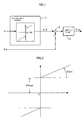
- FIG. 1 illustrates the principle constitution of the present invention.
- An estimated (or detected) motor rotation number (speed) ⁇ is subject to an advance angle control by an advance angle element 11 composing an advance angle control section, an angle estimated value ⁇ e is added to the angle ⁇ which is subject to the advance angle control by an adding section 12, the angle estimated value is limited to within "0° to 360°" by a limiting section 13, and an angle estimated value ⁇ ea which is subject to the advance angle control is outputted and the angle estimated value ⁇ ea is used for a vector arithmetic.
- the limiting section 13 has a function for limiting the angle estimated value ⁇ ea within the range of "0° to 360°".
- the angle estimated value ⁇ e is limited within the range of "0° to 360°", but when the angle ⁇ is added, the angle estimated value ⁇ e occasionally exceeds 360°.
- the exceeded value is returned to the range of "0° to 360°". For example, when the angle estimated value ⁇ e is "350” and the angle ⁇ is "20”, an added value is “370”, but the "10” is obtained by "370 - 360” by the limiting section 13.
- the rotation number ⁇ is subject to the advance angle control so as to be added to the angle estimated value ⁇ e and the added result is used when the current command value is generated, the delay amount of the motor current can be compensated, and thus the torque ripples and an operation noise can be reduced.
- FIG. 3 illustrates an entire constitutional example to which the present invention is applied.
- a current command Iref is inputted to the limiting section 1, the current command Iref1 whose upper and lower values are limited by the limiting section 1 is inputted to an Id calculating section 2 and an Iq calculating section 3.
- the Id calculating section 2 calculates a d-axis current in the vector control.
- the d-axis current is used for controlling a magnetic force of the motor (torque constant), making weakening magnetic field control which weakens an electric field and thus improving the feature of the high-speed rotation.
- the Iq calculating section 3 calculates a q-axis current in the vector control, and obtains the q-axis current based on a relationship of input/output energy of the motor 10.
- the d-axis current Idref from the Id calculating section 2 is inputted to the Iq calculating section 3 and a dq/abc (two-phase/three-phase) converting section 4.
- the q-axis current Iqref calculated in the Iq calculating section 3 is also inputted to the dq/abc converting section 4, and converted three-phase currents Iaref, Ibref and Icref are outputted from the dq/abc converting section 4.
- Differences (errors) between the three-phase currents Iaref, Ibref, Icref and the motor currents (Im) Ia, Ib, Ic are obtained by subtracters SB1, SB2 and SB3, respectively.
- the differences are PI-controlled by PI control sections 101, 102 and 103, respectively, and the PI-controlled voltages are added to back EMFs EMFa, EMFb and EMFc, respectively, by adders AD1, AD2 and AD3 so that the added values are inputted to a PWM circuit 5.
- the motor 10 is controlled to be driven via a driving circuit 6.
- the three-phase motor currents Ia, Ib and Ic are feedbacked to the subtracters SB1, SB2 and SB3, respectively, and are inputted to an EMF (back electromotive voltage) calculating section 7 and an estimating section 100.
- EMF back electromotive voltage
- Three-phase motor voltages Va, Vb and Vc are inputted to the EMF calculating section 7 and the estimating section 100.
- the three-phase back EMFs Ea, Eb and Ec calculated by the EMF calculating section 7 are inputted to an abc/dq (three-phase/two-phase) converting section 8, and voltages Ed and Eq converted into two-phase voltages are inputted to the Iq calculating section 3 which calculates the q-axis current.
- a Hall signal is inputted from a Hall sensor which detects a rotor position of the motor 100 to the estimating section 100.
- the rotation number ⁇ estimated by the estimating section 100 is inputted to advance angle control sections 110 and 120, and to the Iq calculating section 3.
- the advance angle control section 110 is composed of an advance angle element 111 and an adder 112
- the advance angle control section 120 is composed of an advance angle element 121 and an adder 122.
- An angle ⁇ 1 which is subject to the advance angle control by the advance angle element 111 is inputted to the adder 112
- an angle ⁇ 2 which is subject to the advance angle control by the advance angle element 121 is inputted to the adder 122.
- An angle estimated value ⁇ e estimated by the estimating section 100 is inputted to the adder 112 of the advance angle control section 110 and the adder 122 of the advance angle control section 120.
- An angle estimated value ⁇ 1 which is subject to the advance angle control by the advance angle control section 110 is inputted to the abc/dq converting section 8 and the dq/abc converting section 4. Further, an angle estimated value ⁇ 2 which is subject to the advance angle control by the advance angle control section 120 is inputted to a look-up table 130, and the look-up table 130 generates three-phase voltages EMFa, EMFb and EMFc, and they are inputted to the adders AD1, AD2 and AD3, respectively.
- the limiting sections which limit the ranges of the angles are omitted in the advance angle control sections 110 and 120.
- the back EMFs EMFa, EMFb and EMFc from the look-up table 130 are used for a feed-forward control of the electric current control, and the angle ⁇ 2 which is subject to the advance angle control is used for correcting an error based on a delay of the angle estimated value ⁇ e.
- the angle ⁇ 1 which is subject to the advance angle control is used for correcting a delay of the motor current Im.
- the advance angle estimated value ⁇ e estimated by the estimating section 100 is estimated from motor voltages Va, Vb and Vc and motor currents Ia, Ib and Ic using a motor model (for example, Japanese Patent Application No. 2003-101195 ) and a Hall signal (for example, Japanese Patent Application No. 2003-101195 ). For this reason, a small amount of error based on measurement of voltage or electric current and a delay of a signal process (filter, reading of voltage or electric current, a Hall signal or the like) is always present in the angle estimated value ⁇ e.
- the delay is a function of the rotary speed of the rotor, and as the speed is higher, the delay becomes larger.
- the back EMFs EMFa, EMFb and EMFc for the feed-forward control are read from the look-up table 130 based on the angle ⁇ 2, and the input into the look-up table 130 is controlled so that the delay can be easily corrected.
- the delay of the motor current in the control system is caused by an inductance L of the motor 10, and this delay is a function of the speed ⁇ .
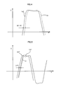
- the waveform chart in FIG. 4 illustrates an example of the delay of the current response, and the current command Iref is changed from positive into negative, but the motor current Im does not track the current command Iref at a high speed. That is to say, "dim/dt" is not sufficiently fast.
- the expression (5) shows the followings. That is to say, when the inductance L is large, dim/d ⁇ is small and the delay is large. When the motor speed ⁇ m is large, dim/d ⁇ is small and the delay is large. In other words, the delay of the current depends on the impedance of the motor 10 and is the function of the speed ⁇ .
- the delay of the motor current Im can be reduced or cancelled previously by shifting the current command Iref by the angle ⁇ 1. That is to say, in the control system of the present invention, since the current commands Iaref, Ibref and Icref from the dq/abc converting section 4 are calculated by using the look-up table, the delay error can be easily corrected.
- the angle ⁇ 1 is used for calculating the current commands Iaref, Ibref and Icref (for example, Japanese Patent Application No. 2002-345135 ).
- I q ref 2 / 3 ⁇ T ref ⁇ ( ⁇ m / E q ) ⁇ I d ref ⁇ ( E d / E q )
- FIG. 5 illustrates a state that the current command Iref is corrected, and the current command Iref with the same waveform shifts by the angle (time) ⁇ 1.
- the motor current Im delays from the corrected current command Iref' but does not delay from the original current command Iref.
- the back EMFs (EMFa, EMFb and EMFc) are generated by a back EMF calculating circuit 21 as shown in FIG. 8, and the back EMF calculating circuit 21 is composed of a normalized back EMF calculating circuit 21-1 and a rotation number correcting circuit 21-2.
- the normalized back EMF calculating circuit 21-1 calculates a back EMF EMF 1000 when the motor is at 1000 [rpm] based on a corrected electric angle ⁇ 2.
- the rotation number correcting circuit 21-2 since the back EMF is proportional to the rotation number and thus is expressed by the following expression (10). For example, when the motor is at 1100 [rpm], the value calculated by the normalized back EMF calculating circuit 21-1 may be made to be 1.1 times.
- EMF a , b , c ( ⁇ / 1000 ) ⁇ EMF 1000
- the normalized back EMF calculating circuit 21-1 is explained. Since the waveform of the back EMF generated by the electric angle ⁇ varies with types and design values of actual motors, the normalized back EMF calculating circuit 21-1 obtains the back EMF EMF 1000 at 1000 [rpm] according to the actual measurement using a designed actual motor. When the corrected electric angle ⁇ 2 which does not delay is inputted from the advance angle control section 120 into the back EMF calculating circuit 21, the accurate back EMFs EMFa, EMFb and EMFc are calculated.
- the normalized back EMF calculating circuit 21-1 and the rotation number correcting circuit 21-2 calculate the back EMFs EMFa, EMFb and EMFc with respect to the corrected electric angle ⁇ 2 in advance and the look-up table is formed (look-up table 130), the high-speed calculation can be made.
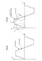
- FIG. 9A illustrates a relationship between the delayed back EMF EMF1 which is calculated by the back EMF calculating circuit and the actual back EMF.
- FIG. 9B illustrates a relationship between the actual back EMF and the back EMF "K ⁇ EMF" which is subject to gain adjustment.
- a portion where the torque ripples are difficultly reduced by an electric current control circuit or the like is surrounded by an oval A.
- a portion surrounded by an oval B is a portion where the delay of the back EMF can be compensated as an error and a disturbance by the electric current control circuit.
- similar compensation can be made by the electric current control circuit.
- the delay of the motor current can be compensated accurately, thereby reducing the torque ripples and the operation noise of the motor.
- the steering feeling can be further improved. That is to say, the output torque ripples of the motor can be reduced, and the electric power steering apparatus whose handle operation is smooth and whose noise is less can be realized.
- the advance angle control when the delay between the information about the actual motor and the information used for the control is compensated by the advance angle control, the motor current Im can be controlled accurately. For this reason, the torque ripples and the operation noise of the motor can be reduced.
- the advance angle control can be made by the simple linear function, and the steering feeling can be improved by the compensation of the delay.
- the torque ripples can be reduced and device can be applied to high-performance electric power steering for automobiles and vehicles.
Landscapes
- Engineering & Computer Science (AREA)
- Chemical & Material Sciences (AREA)
- Combustion & Propulsion (AREA)
- Transportation (AREA)
- Mechanical Engineering (AREA)
- Control Of Ac Motors In General (AREA)
- Power Steering Mechanism (AREA)
- Control Of Motors That Do Not Use Commutators (AREA)
- Steering Control In Accordance With Driving Conditions (AREA)
Applications Claiming Priority (2)
| Application Number | Priority Date | Filing Date | Title |
|---|---|---|---|
| JP2004005067A JP4604493B2 (ja) | 2004-01-13 | 2004-01-13 | 電動パワーステアリング装置の制御装置 |
| PCT/JP2004/019661 WO2005069475A1 (ja) | 2004-01-13 | 2004-12-21 | 電動パワーステアリング装置の制御装置 |
Publications (1)
| Publication Number | Publication Date |
|---|---|
| EP1708355A1 true EP1708355A1 (en) | 2006-10-04 |
Family
ID=34792086
Family Applications (1)
| Application Number | Title | Priority Date | Filing Date |
|---|---|---|---|
| EP04808012A Withdrawn EP1708355A1 (en) | 2004-01-13 | 2004-12-21 | Device for controlling motor-driven power steering device |
Country Status (4)
| Country | Link |
|---|---|
| US (1) | US7443131B2 (enExample) |
| EP (1) | EP1708355A1 (enExample) |
| JP (1) | JP4604493B2 (enExample) |
| WO (1) | WO2005069475A1 (enExample) |
Cited By (4)
| Publication number | Priority date | Publication date | Assignee | Title |
|---|---|---|---|---|
| EP1955926A3 (en) * | 2007-02-07 | 2008-12-03 | NSK Ltd. | Control device for electric power steering apparatus |
| EP2731260A4 (en) * | 2011-07-04 | 2015-09-09 | Nissan Motor | INVERTER CONTROL DEVICE AND INVERTER CONTROL METHOD |
| EP2899876A4 (en) * | 2012-09-21 | 2015-12-09 | Nissan Motor | INVERTER CONTROL DEVICE AND INVERTER CONTROL METHOD |
| EP3040253A1 (en) * | 2014-12-24 | 2016-07-06 | Jtekt Corporation | Steering control apparatus |
Families Citing this family (12)
| Publication number | Priority date | Publication date | Assignee | Title |
|---|---|---|---|---|
| EP1722469A1 (en) * | 2004-02-23 | 2006-11-15 | NSK Ltd., | Motor-driven power steering device control device |
| EP1860766B1 (en) * | 2005-03-17 | 2015-10-28 | Nsk Ltd. | Electric power steering device control method and apparatus |
| US8080957B2 (en) * | 2006-04-11 | 2011-12-20 | Nsk, Ltd. | Motor control device and motor-driven power steering system using the same |
| KR101194948B1 (ko) * | 2006-07-19 | 2012-10-25 | 현대모비스 주식회사 | 토크 리플 저감방법 |
| JP2010105763A (ja) * | 2008-10-29 | 2010-05-13 | Hitachi Ltd | 電力変換装置およびそれを用いたエレベータ |
| JP5545871B2 (ja) * | 2010-12-24 | 2014-07-09 | 株式会社小野測器 | 制御装置 |
| JP2013023176A (ja) * | 2011-07-26 | 2013-02-04 | Mitsuba Corp | モータ制御装置 |
| JP5952009B2 (ja) * | 2012-01-31 | 2016-07-13 | 本田技研工業株式会社 | 電動パワーステアリング装置 |
| US10177699B2 (en) * | 2015-10-16 | 2019-01-08 | Nsk Ltd. | Motor control unit and electric power steering apparatus equipped with the same |
| KR20190109528A (ko) * | 2017-02-14 | 2019-09-25 | 케이에스알 아이피 홀딩스 엘엘씨. | 고조파 보상을 위한 시스템 및 방법 |
| WO2019163552A1 (ja) * | 2018-02-20 | 2019-08-29 | 日本電産株式会社 | モータ制御システム、およびパワーステアリングシステム |
| JP7779202B2 (ja) * | 2022-05-26 | 2025-12-03 | 日本精工株式会社 | モータ制御装置、電動アクチュエータおよび電動パワーステアリング装置 |
Family Cites Families (19)
| Publication number | Priority date | Publication date | Assignee | Title |
|---|---|---|---|---|
| JP2830274B2 (ja) | 1990-01-17 | 1998-12-02 | 株式会社明電舎 | 可変速駆動装置の電流制御方式 |
| JP3396114B2 (ja) * | 1995-06-26 | 2003-04-14 | サンデン株式会社 | ブラシレスモータの制御装置 |
| JP3684661B2 (ja) * | 1996-03-04 | 2005-08-17 | 日産自動車株式会社 | 交流電動機の制御装置 |
| JPH1175396A (ja) * | 1997-08-29 | 1999-03-16 | Seiko Epson Corp | 位置センサレス・モータ駆動装置 |
| JP3168986B2 (ja) * | 1998-05-28 | 2001-05-21 | トヨタ自動車株式会社 | 電動機制御装置および制御方法 |
| JP4746252B2 (ja) | 1998-07-08 | 2011-08-10 | イビデン株式会社 | 多層プリント配線板 |
| JP3668866B2 (ja) * | 1999-07-02 | 2005-07-06 | トヨタ自動車株式会社 | 交流モータの電気制御装置 |
| US6373211B1 (en) | 1999-09-17 | 2002-04-16 | Delphi Technologies, Inc. | Extended speed range operation of permanent magnet brushless machines using optimal phase angle control in the voltage mode operation |
| JP2002078391A (ja) * | 2000-08-30 | 2002-03-15 | Hitachi Ltd | 交流電動機の駆動システム |
| JP4581227B2 (ja) * | 2000-11-14 | 2010-11-17 | パナソニック株式会社 | 洗濯機のモータ駆動装置 |
| JP3502040B2 (ja) | 2000-12-27 | 2004-03-02 | 本田技研工業株式会社 | ブラシレスdcモータの定数検出装置およびブラシレスdcモータの制御装置およびブラシレスdcモータの定数検出用プログラム |
| JP3755582B2 (ja) * | 2001-02-08 | 2006-03-15 | 三菱電機株式会社 | 電動機制御装置 |
| JP2002345135A (ja) | 2001-05-11 | 2002-11-29 | Daito Denzai Co Ltd | 支線ガ−ド、及びその製造方法 |
| JP4779233B2 (ja) | 2001-06-04 | 2011-09-28 | 日本精工株式会社 | ブラシレスモータ駆動制御装置 |
| JP3559258B2 (ja) * | 2001-07-30 | 2004-08-25 | 三菱電機株式会社 | ステアリング制御装置 |
| JP2003101195A (ja) | 2001-09-26 | 2003-04-04 | Nec Toppan Circuit Solutions Inc | 半導体装置用基板及びその製造方法 |
| JP2003189658A (ja) | 2001-12-12 | 2003-07-04 | Yaskawa Electric Corp | 遅れ補償電動機制御装置 |
| JP4103430B2 (ja) | 2002-04-09 | 2008-06-18 | 株式会社ジェイテクト | 電動パワーステアリング装置 |
| JP4000896B2 (ja) * | 2002-04-24 | 2007-10-31 | 株式会社ジェイテクト | モータ制御装置 |
-
2004
- 2004-01-13 JP JP2004005067A patent/JP4604493B2/ja not_active Expired - Fee Related
- 2004-12-12 US US10/585,990 patent/US7443131B2/en not_active Expired - Lifetime
- 2004-12-21 WO PCT/JP2004/019661 patent/WO2005069475A1/ja not_active Ceased
- 2004-12-21 EP EP04808012A patent/EP1708355A1/en not_active Withdrawn
Non-Patent Citations (1)
| Title |
|---|
| See references of WO2005069475A1 * |
Cited By (6)
| Publication number | Priority date | Publication date | Assignee | Title |
|---|---|---|---|---|
| EP1955926A3 (en) * | 2007-02-07 | 2008-12-03 | NSK Ltd. | Control device for electric power steering apparatus |
| EP2731260A4 (en) * | 2011-07-04 | 2015-09-09 | Nissan Motor | INVERTER CONTROL DEVICE AND INVERTER CONTROL METHOD |
| US9178463B2 (en) | 2011-07-04 | 2015-11-03 | Nissan Motor Co., Ltd. | Inverter control device and inverter control method |
| EP2899876A4 (en) * | 2012-09-21 | 2015-12-09 | Nissan Motor | INVERTER CONTROL DEVICE AND INVERTER CONTROL METHOD |
| EP3040253A1 (en) * | 2014-12-24 | 2016-07-06 | Jtekt Corporation | Steering control apparatus |
| US9650067B2 (en) | 2014-12-24 | 2017-05-16 | Jtekt Corporation | Steering control apparatus |
Also Published As
| Publication number | Publication date |
|---|---|
| US20070158132A1 (en) | 2007-07-12 |
| JP4604493B2 (ja) | 2011-01-05 |
| JP2005199735A (ja) | 2005-07-28 |
| US7443131B2 (en) | 2008-10-28 |
| WO2005069475A1 (ja) | 2005-07-28 |
Similar Documents
| Publication | Publication Date | Title |
|---|---|---|
| EP1470988B1 (en) | Electric power steering apparatus | |
| US8150580B2 (en) | Motor controller and electric power steering system | |
| EP1961643B1 (en) | Motor controller and electric power steering apparatus | |
| EP1683705B1 (en) | Electric power steering device | |
| US7574294B2 (en) | Controller for electric power steering device | |
| US7443131B2 (en) | Control device for electric power steering apparatus | |
| JP5365701B2 (ja) | 電動パワーステアリング装置 | |
| CN102687385A (zh) | 电动动力转向装置 | |
| EP2262099A1 (en) | Motor control device and electric power steering device | |
| EP1849681B1 (en) | Electric power steering apparatus | |
| CN1741367B (zh) | 电动机的无位置传感器控制电路 | |
| EP1863163B1 (en) | Motor controller | |
| JP5397664B2 (ja) | モータ制御装置 | |
| EP1681762B1 (en) | Synchronous motor driving system and method | |
| JP3668866B2 (ja) | 交流モータの電気制御装置 | |
| JP5444697B2 (ja) | モータ制御装置および電動パワーステアリング装置 | |
| JP2011131726A (ja) | 電動パワーステアリング装置 | |
| JP2011230531A (ja) | モータ制御装置 | |
| JP4556464B2 (ja) | 電動パワーステアリング装置の制御装置 | |
| JP2008155683A (ja) | 電気式動力舵取装置 | |
| JP5287698B2 (ja) | 電動パワーステアリング装置 |
Legal Events
| Date | Code | Title | Description |
|---|---|---|---|
| PUAI | Public reference made under article 153(3) epc to a published international application that has entered the european phase |
Free format text: ORIGINAL CODE: 0009012 |
|
| 17P | Request for examination filed |
Effective date: 20060712 |
|
| AK | Designated contracting states |
Kind code of ref document: A1 Designated state(s): DE FR |
|
| DAX | Request for extension of the european patent (deleted) | ||
| RBV | Designated contracting states (corrected) |
Designated state(s): DE FR |
|
| STAA | Information on the status of an ep patent application or granted ep patent |
Free format text: STATUS: THE APPLICATION HAS BEEN WITHDRAWN |
|
| 18W | Application withdrawn |
Effective date: 20090528 |