EP1706239B1 - Schleifvorrichtung - Google Patents
Schleifvorrichtung Download PDFInfo
- Publication number
- EP1706239B1 EP1706239B1 EP04801172A EP04801172A EP1706239B1 EP 1706239 B1 EP1706239 B1 EP 1706239B1 EP 04801172 A EP04801172 A EP 04801172A EP 04801172 A EP04801172 A EP 04801172A EP 1706239 B1 EP1706239 B1 EP 1706239B1
- Authority
- EP
- European Patent Office
- Prior art keywords
- grinding
- units
- screen
- grinding apparatus
- screen unit
- Prior art date
- Legal status (The legal status is an assumption and is not a legal conclusion. Google has not performed a legal analysis and makes no representation as to the accuracy of the status listed.)
- Expired - Lifetime
Links
Images



Classifications
-
- B—PERFORMING OPERATIONS; TRANSPORTING
- B24—GRINDING; POLISHING
- B24B—MACHINES, DEVICES, OR PROCESSES FOR GRINDING OR POLISHING; DRESSING OR CONDITIONING OF ABRADING SURFACES; FEEDING OF GRINDING, POLISHING, OR LAPPING AGENTS
- B24B55/00—Safety devices for grinding or polishing machines; Accessories fitted to grinding or polishing machines for keeping tools or parts of the machine in good working condition
- B24B55/06—Dust extraction equipment on grinding or polishing machines
- B24B55/10—Dust extraction equipment on grinding or polishing machines specially designed for portable grinding machines, e.g. hand-guided
- B24B55/102—Dust extraction equipment on grinding or polishing machines specially designed for portable grinding machines, e.g. hand-guided with rotating tools
-
- B—PERFORMING OPERATIONS; TRANSPORTING
- B08—CLEANING
- B08B—CLEANING IN GENERAL; PREVENTION OF FOULING IN GENERAL
- B08B15/00—Preventing escape of dirt or fumes from the area where they are produced; Collecting or removing dirt or fumes from that area
- B08B15/04—Preventing escape of dirt or fumes from the area where they are produced; Collecting or removing dirt or fumes from that area from a small area, e.g. a tool
-
- B—PERFORMING OPERATIONS; TRANSPORTING
- B24—GRINDING; POLISHING
- B24B—MACHINES, DEVICES, OR PROCESSES FOR GRINDING OR POLISHING; DRESSING OR CONDITIONING OF ABRADING SURFACES; FEEDING OF GRINDING, POLISHING, OR LAPPING AGENTS
- B24B7/00—Machines or devices designed for grinding plane surfaces on work, including polishing plane glass surfaces; Accessories therefor
- B24B7/10—Single-purpose machines or devices
- B24B7/18—Single-purpose machines or devices for grinding floorings, walls, ceilings or the like
- B24B7/182—Single-purpose machines or devices for grinding floorings, walls, ceilings or the like for walls and ceilings
-
- B—PERFORMING OPERATIONS; TRANSPORTING
- B24—GRINDING; POLISHING
- B24B—MACHINES, DEVICES, OR PROCESSES FOR GRINDING OR POLISHING; DRESSING OR CONDITIONING OF ABRADING SURFACES; FEEDING OF GRINDING, POLISHING, OR LAPPING AGENTS
- B24B7/00—Machines or devices designed for grinding plane surfaces on work, including polishing plane glass surfaces; Accessories therefor
- B24B7/10—Single-purpose machines or devices
- B24B7/18—Single-purpose machines or devices for grinding floorings, walls, ceilings or the like
- B24B7/186—Single-purpose machines or devices for grinding floorings, walls, ceilings or the like with disc-type tools
Definitions
- the present invention concerns a grinding apparatus including a number of grinding units, a number of drive units and a number of screen units, where a number of the grinding units are enclosed by at least one of the screen units, and where at least one of the screen units is arranged with a pipe connection adapted for connecting one or more suction units.
- the person using the grinding apparatus is usually to walk with respiratory protection and safety goggles for protecting himself against the abraded material whirled into the air while using the grinding apparatus.
- Another problem with grinding large elements or grinding high-level surfaces is that it may be difficult to stand on the ground and guide the grinding apparatus manually. I.e. scaffolding is to be used in order to grind the surface of the elements safely.
- a solution to this problem is to mount the grinding apparatus on a longitudinally adjustable handle whereby it is possible to reach the top of the element.
- CH-A5-666 648 discloses a handheld grinding apparatus that includes two grinding units, a drive unit and a screen member, where the two grinding units are enclosed by the screen unit which is arranged with a pipe connection for connecting a suction unit.
- the spacer member which is provided along a lower edge on the screen unit, only has one function, namely to prevent abraded material from being spread to the surroundings, as abraded material spread to the surroundings can be sucked out via the pipe connection.
- EP 0 286 051 discloses a grinding apparatus according to the preamble of claim 1.
- the screen unit with the pipe connection is designed along a lower edge with a number of spacer members that are arranged adjustable and replaceable, and with a number of sealing members that fit tightly to an underlying surface, that the spacer members establish an spacing adjustment of the grinding units relatively to an underlying surface, and that the sealing members interact with the suction units for forming a vacuum that holds the grinding apparatus against the said surface during operation.
- the grinding apparatus includes a number of grinding units, a number of drive units and a number of screen units, where a number of the grinding units are enclosed by at least one of the screen units.
- At least one of the screen units are arranged with a pipe connection which is adapted for connecting to one or more suction units that form vacuum in the screen units, the vacuum holding the grinding apparatus against the surface during operation.
- the screen unit with the pipe connection along a lower edge includes a number of adjustable and replaceable spacer members and a number of sealing members.
- the sealing members provide for the screen unit fitting tightly against the surface and so that unnecessary false air does not enter the screen unit during operation, so that the vacuum can be maintained with a minimum of suction from the suction unit.
- sealing members may e.g. be Teflon® skirts that are connected either along the lower edge of the screen or in connection with the spacer members.
- these Teflon® skirts are made so that they have a top tie so that they by applying the screen unit to a surface will crease a little upwards and outwards, whereby a part of the Teflon® skirts will always bear down against the surface. This entails that there is a tight interface between the screen unit and the surface.
- Sealing members may, however, be of other types, such as e.g. rubber mouldings or an enclosing collar member of e.g. flexible plastic/rubber providing tight fit between the screen unit and the surface.
- the grinding apparatus may be placed on a ceiling surface or a vertical surface without falling down, or without using force for holding the grinding apparatus in place.
- the adjustable and replaceable spacer members enable an adjustment of the spacing of the grinding units in relation to the surface, entailing that it is possible to control the grinding efficiency and/or to move the grinding apparatus across a surface without grinding the surface.
- the spacer members may e.g. be brushes that provide for the screen unit to be moved around on the surface without leaving any marks, and which furthermore implies easy dragging of the screen unit across the surface.
- the brushes will furthermore cause the abraded material to be kept inside the screen unit before being sucked away, and it will therefore not disappear out under the edge of the screen unit.
- the screen unit with the pipe connection encloses a number of the grinding units.
- the screen unit contains one or more rotating grinding units, and the vacuum provides for holding the grinding apparatus against the surface and simultaneously provides for removing abraded material.
- the screen unit with the pipe connection is connected to satellite screen units that each enclose a number of the grinding units.
- a central screen unit is provided, for example, to which the suction unit is connected and a number of satellite screen unit enclosing a number of grinding units, and where it is the central screen unit that provides for the grinding apparatus being held firmly against the surface while the surface grinding occurs in the connected satellite screen units.
- these are preferably connected with the suction unit, however, without creating so much vacuum in the screen units that they are hold fast to the surface.
- the adjustable spacer members and the sealing members enable moving the grinding apparatus without any problems across the surface, entailing that no great force is to be applied for moving the grinding apparatus. This is a great advantage if the grinding apparatus is suspended at great height on an element and is to be controlled by means of a handle.
- each of the screen units includes a number of wheels. This may be applicable if grinding is only to be performed spotwise on the surface and the grinding apparatus is to be moved a distance before reaching the next grinding spot. Furthermore, wheels will also be an advantage if the grinding apparatus is to pass an uneven surface.
- the screen units are articulated connected with a number of linking rods, entailing that the grinding apparatus can be used for grinding one or more laterally disposed surfaces with different inclination. This may be particularly applicable when grinding corners or edges.
- the screen units include two screens that are arranged preferably coaxially.
- the grinding apparatus may be used together with e.g. water so that the grinding units and the water is kept within the inner screen, while the suction unit produces vacuum in the interspace between the inner screen and the outer screen, so that the grinding apparatus can be held fast to the surface.
- the screen unit is adapted so that it is connected with a longitudinally adjustable handle. This entails that one may stand upright and polish a surface so that a ceiling surface or a side face may be reached by means of the handle without having to move or to get down on the knees.
- a screen unit connected with a handle can be used like a broom, so that one may stand over a lying surface and move the grinding apparatus back and forth across the surface.
- the grinding apparatus may be provided with a number of motors for movement and which may be remotely controlled.
- the grinding apparatus may be used for different types of grinding units that may be designed as circular grinding wheels, cylindric grinding rollers and/or polygonal grinding plates.
- the grinding units are circular grinding wheels disposed in the screen unit so that the face of the grinding wheel is parallel with the surface.
- the rotation of the grinding wheel will provide a surface treatment which is a circular grinding.
- the grinding units will be cylindric grinding rollers disposed so that their axes of rotation are approximately parallel with the surface.
- the rotation of the grinding roller will provide a surface treatment which is a linear grinding.
- the grinding units may be polygonal grinding plates disposed in the screen unit so that the face of the grinding plate is parallel with the surface, and instead of rotating movement, the grinding plate has a cyclic movement back and forth.
- grinding members may e.g. be polishing cloth, sandpaper, brushes, steel brushes, wire brushes or similar, which by moving across a surface will provide grinding/polishing of the surface.
- the grinding units are replaceable, i.e. they may be exchanged quickly and easily. It is thus possible to use the same grinding apparatus/grinding units for rough grinding, fine grinding or finishing a surface.
- the screen units are adapted with pipe connections for connecting suction units.
- suction units are e.g. a vacuum pump, a suction cleaner and/or fans.
- the suction unit is a vacuum pump which is placed stationarily in the area in which the screen unit is wanted to be used, and it is connected to the screen unit via e.g. hoses, whereby the grinding apparatus is held onto the surface and the abraded material is sucked into a container for storage until disposal of the abraded material.
- the suction unit is a suction cleaner which may be portable or mobile, which then may be carried around the item to be ground.
- the suction unit is a suction cleaner mounted directly on the grinding apparatus.
- the suction units may be fans which by means of a ventilator forms a subpressure/vacuum in the screen units, whereby the grinding apparatus is held onto the surface and the abraded material is removed.
- the grinding apparatus is designed with a number of screen units with at least one pipe connection for connecting one or more suction units that may form a vacuum in the screen unit and suck the abraded material via the pipe connection out from the screen unit and on to e.g. a collecting container.
- the grinding apparatus is designed so that a plurality of grinding units are mounted in the same screen unit.
- a plurality of grinding units are mounted in the same screen unit.
- These grinding wheels may be disposed overlapping and displaced, or be juxtaposed.
- the drive units used for driving the grinding units are motor units that are powered either hydraulically, pneumatically or electrically.
- the drive unit will be an electric motor which is either provided power via batteries or is connected to the electricity grid.
- the screen units may, in order to move the grinding apparatus when suspended on a surface, include a damper device for reducing the vacuum in the screen unit, by e.g. allowing the damper device to let false air enter the screen unit.
- This damper device will typically be disposed in connection with the pipe connection so that false air is let into the pipe connection whereby the vacuum in the screen unit is reduced.
- the damper device is adjustable so that the user may adjust the vacuum when moving around with the screen unit.
- the grinding apparatus is intended for application to the grinding of surfaces, e.g. the hull of a ship, windmill wings or tower elements. These surfaces may be a mix of plane surfaces and curved surfaces, where it is possible to use either a grinding apparatus with a grinding unit enclosed by a screen unit, or a grinding apparatus with a plurality of grinding units that are enclosed by a number of screen units.
- a grinding apparatus with a screen unit weighs about 3 kgs and may be used with a usual household suction cleaner with a wattage of 1000 - 2500 W, and this suction cleaner provides for producing sufficient vacuum (0.5-0.9 bar) for the grinding apparatus to be self-attaching and movable at the same time.
- Fig. 1 shows a grinding apparatus 1 including a screen unit 2 which encloses a circular grinding unit 3.
- the screen unit 2 comprises:
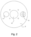
- Fig. 2 shows a plane view of the screen unit 2 where it is possible to see that it is circular and that it has a pipe connection 4 and a damper device 5 arranged at each side of the centrally disposed drive unit 11.
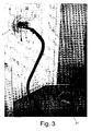
- Fig. 3 shows a view of a grinding apparatus 1 on a wall 20, where a suction unit 21 in the form of a suction cleaner is connected to the pipe connection 4 on the screen unit 2.
- the sucking action from the suction unit 21 produces vacuum inside the screen unit 2, where sealing member 8 in the shape of a skirt provides for the screen unit 2 to fit tightly to the wall 20.
- the vacuum from suction unit 21 is powerful enough to make grinding apparatus 1 stay hanging on the wall 20, implying that the grinding apparatus 1 is self-attaching, and force is only required for moving grinding apparatus 1 vertically or horizontally, and not for lifting the grinding apparatus 1.
- Fig. 4 shows a screen unit 2 where it may be seen that grinding unit 3 is a circular wheel with a number of grinding members 9 in the shape of sandpaper, and that the lower edge 6 of screen unit 2 is connected to spacer members 7 in the form of brushes and which is enclosed by the sealing member 8 in the form of a plastic skirt.
- Fig. 5 shows an alternative embodiment of the invention where four circular grinding units 3 are surrounded by a screen unit 2 which is provided with a central pipe connection 4 for establishing vacuum inside the vacuum unit 2.
- Each grinding unit 3 is shown provided with a drive unit 11.
- This embodiment of the invention may e.g. be used if very large surfaces are to be ground. Furthermore, by controlling the direction of rotation of the grinding units 3, it is possible to control the movement of the screen unit 2.
- Fig. 6 shows a further alternative embodiment of the invention, where a central screen unit 2 is designed with a pipe connection 5 of connecting a suction unit (not shown) and is articulated connected with linking rods 22 to satellite screen units 23 that each enclose a grinding unit (not shown) which is powered by a drive unit 11.
Landscapes
- Engineering & Computer Science (AREA)
- Mechanical Engineering (AREA)
- Grinding-Machine Dressing And Accessory Apparatuses (AREA)
- Finish Polishing, Edge Sharpening, And Grinding By Specific Grinding Devices (AREA)
- Polarising Elements (AREA)
- Encapsulation Of And Coatings For Semiconductor Or Solid State Devices (AREA)
- Disintegrating Or Milling (AREA)
- Constituent Portions Of Griding Lathes, Driving, Sensing And Control (AREA)
- Soft Magnetic Materials (AREA)
- Crushing And Grinding (AREA)
Claims (11)
- Schleifvorrichtung (1), mit mehreren Schleifeinheiten (3), mehreren Antriebseinheiten (11) und mehreren Abschirmeinheiten (2), wobei mehrere Schleifeinheiten (3) durch wenigstens eine der Abschirmeinheiten (2) umschlossen ist und wobei wenigstens eine der Abschirmeinheiten (2) mit einer Rohrverbindung (4) versehen ist, die dazu ausgelegt ist, eine Verbindung mit einer oder mit mehreren Saugeinheiten (21) herzustellen, wobei die Abschirmeinheit (2) zusammen mit der Rohrverbindung (4) längs einer Unterkante (6) mit mehreren Abstandshalterelementen (7), die austauschbar ausgebildet sind, und mit mehreren Dichtungselementen (8), die sich eng an eine darunter befindliche Oberfläche anschmiegen, ausgebildet ist, wobei die Abstandshalterelemente (7) eine Zwischenraumeinstellung der Schleifeinheiten (3) in Bezug auf eine darunter befindliche Oberfläche schaffen und wobei die Dichtungselemente (8) mit den Saugeinheiten (21) in Wechselwirkung stehen, um einen Unterdruck zu erzeugen, der die Schleifvorrichtung (1) während des Betriebs gegen die Oberfläche gehalten unterstützt, dadurch gekennzeichnet, dass die Abstandshalterelemente einstellbar ausgebildet sind.
- Schleifvorrichtung (1) nach Anspruch 1, dadurch gekennzeichnet, dass die Abschirmeinheit (2) mit der Rohrverbindung (4) mehrere Schleifeinheiten (3) umschließt.
- Schleifvorrichtung (1) nach Anspruch 1, dadurch gekennzeichnet, dass die Abschirmeinheit (2) mit der Rohrverbindung (4) mit Satellitenabschirmeinheiten (23) verbunden ist, die jeweils mehrere der Schleifeinheiten (3) umschließen.
- Schleifvorrichtung (1) nach einem der Ansprüche 1-3, dadurch gekennzeichnet, dass jede der Abschirmeinheiten (2, 23) mehrere Räder enthält.
- Schleifvorrichtung (1) nach einem der Ansprüche 1-4, dadurch gekennzeichnet, dass die Abschirmeinheiten (2, 23) mit mehreren Verbindungsstangen (22) schwenkbar verbunden sind.
- Schleifvorrichtung (1) nach einem der Ansprüche 1-5, dadurch gekennzeichnet, dass die Abschirmeinheiten (2, 23) zwei Schirme enthalten, die vorzugsweise koaxial angeordnet sind.
- Schleifvorrichtung (1) nach einem der Ansprüche 1-6, dadurch gekennzeichnet, dass wenigstens eine der Abschirmeinheiten (2) mit einem in Längsrichtung einstellbaren Griff verbunden ist.
- Schleifvorrichtung (1) nach einem der Ansprüche 1-7, dadurch gekennzeichnet, dass die Schleifeinheiten (3) als kreisförmige Schleifköpfe, zylindrische Schleifwalzen und/oder polygonförmige Schleifplatten geformt sind.
- Schleifvorrichtung (1) nach einem der Ansprüche 1-8, dadurch gekennzeichnet, dass die Abschirmeinheiten (3) austauschbar und höheneinstellbar sind.
- Schleifvorrichtung (1) nach einem der Ansprüche 1-9, dadurch gekennzeichnet, dass die Saugeinheiten (21) Unterdruckpumpen, Saugreiniger und/oder Gebläse sind.
- Schleifvorrichtung (1) nach einem der Ansprüche 1-10, dadurch gekennzeichnet, dass die Abschirmeinheiten (2, 23) eine Dämpfervorrichtung enthalten, um den Unterdruck in der Abschirmeinheit (2, 23) zu reduzieren.
Priority Applications (1)
| Application Number | Priority Date | Filing Date | Title |
|---|---|---|---|
| PL04801172T PL1706239T3 (pl) | 2003-12-08 | 2004-12-08 | Urządzenie szlifierskie |
Applications Claiming Priority (3)
| Application Number | Priority Date | Filing Date | Title |
|---|---|---|---|
| DKPA200301806 | 2003-12-08 | ||
| DK200401457A DK200401457A (da) | 2004-09-24 | 2004-09-24 | Selvsiddende slibeapparat |
| PCT/DK2004/000848 WO2005053902A1 (en) | 2003-12-08 | 2004-12-08 | Grinding apparatus |
Publications (2)
| Publication Number | Publication Date |
|---|---|
| EP1706239A1 EP1706239A1 (de) | 2006-10-04 |
| EP1706239B1 true EP1706239B1 (de) | 2009-04-01 |
Family
ID=34655025
Family Applications (1)
| Application Number | Title | Priority Date | Filing Date |
|---|---|---|---|
| EP04801172A Expired - Lifetime EP1706239B1 (de) | 2003-12-08 | 2004-12-08 | Schleifvorrichtung |
Country Status (10)
| Country | Link |
|---|---|
| US (1) | US7387564B2 (de) |
| EP (1) | EP1706239B1 (de) |
| AT (1) | ATE427186T1 (de) |
| CA (1) | CA2548242A1 (de) |
| DE (1) | DE602004020383D1 (de) |
| DK (1) | DK1706239T3 (de) |
| ES (1) | ES2327237T3 (de) |
| NO (1) | NO20063093L (de) |
| PL (1) | PL1706239T3 (de) |
| WO (1) | WO2005053902A1 (de) |
Cited By (1)
| Publication number | Priority date | Publication date | Assignee | Title |
|---|---|---|---|---|
| CN108788984A (zh) * | 2018-07-03 | 2018-11-13 | 芜湖海平环保科技有限公司 | 一种建筑装饰墙面高效打磨装置 |
Families Citing this family (14)
| Publication number | Priority date | Publication date | Assignee | Title |
|---|---|---|---|---|
| DE102007022194C5 (de) * | 2007-05-11 | 2018-07-12 | Georg Weber | Vorrichtung zum Bearbeiten der Kanten und Oberflächen flächiger Werkstücke |
| DE102008055797A1 (de) | 2008-11-04 | 2010-05-06 | Kai Roscher | Schleifmaschine |
| CA2690224C (en) * | 2009-01-15 | 2012-08-14 | Permasteelisa North America Corporation | Stone wall grinding and polishing system |
| DK178098B1 (da) * | 2009-11-10 | 2015-05-18 | Poul Erik Jespersen | Apparat til slibning/pudsning af en overflade |
| JP5764076B2 (ja) * | 2011-05-23 | 2015-08-12 | 株式会社マキタ | 防水シート及び防水シートを装着した注水式電動工具 |
| DK177274B1 (da) * | 2011-05-27 | 2012-09-10 | Flex Trim As | Slibehoved |
| AT13161U1 (de) * | 2012-05-22 | 2013-07-15 | Isospan Baustoffwerk Gmbh | Fertigwandmodul aus Holzbetonmantelsteinen sowie Verfahren und Vorrichtung zu seiner Herstellung |
| USD748963S1 (en) | 2013-07-05 | 2016-02-09 | Flex-Elektrowerkzeuge Gmbh | Grinding machine |
| JP6687397B2 (ja) * | 2016-01-20 | 2020-04-22 | 積水化学工業株式会社 | 研削装置 |
| DE102018111838A1 (de) * | 2018-05-16 | 2019-11-21 | Festool Gmbh | Mobile Werkzeugmaschine |
| USD906778S1 (en) * | 2019-05-02 | 2021-01-05 | Flex-Elektrowerkzeuge Gmbh | Sanding and polishing machine |
| CN111002135A (zh) * | 2019-12-13 | 2020-04-14 | 周狄超 | 一种建筑装修用墙面磨平装置 |
| CN111283884A (zh) * | 2020-02-21 | 2020-06-16 | 储小燕 | 一种建筑外墙装修施工墙面处理方法 |
| DE102022122584A1 (de) * | 2022-09-06 | 2024-03-07 | Jöst Gmbh | Schleifroboter zum Schleifen einer Oberfläche mit einer Schleifeinrichtung |
Family Cites Families (22)
| Publication number | Priority date | Publication date | Assignee | Title |
|---|---|---|---|---|
| GB489132A (en) | 1937-05-31 | 1938-07-20 | Hubert Scott Paine | Improvements in or relating to portable polishing and like machines |
| US3673744A (en) * | 1971-02-12 | 1972-07-04 | Anders Oimoen | Portable grinder |
| US3722147A (en) | 1971-08-16 | 1973-03-27 | L Brenner | Air driven abrading device |
| US3935678A (en) * | 1972-08-02 | 1976-02-03 | Miksa Marton | Vacuum attachment for abrading machine |
| US3987589A (en) * | 1972-08-02 | 1976-10-26 | Miksa Marton | Vacuum attachment for abrading machine |
| US4135334A (en) | 1976-09-27 | 1979-01-23 | Firma Robert Bosch Gmbh | Dust exhaust hood |
| CH666648A5 (en) | 1985-02-04 | 1988-08-15 | Bernhard Schwarz | Electric hand polishing tool e.g. for car body panels - has rotating polishing discs contained within manually guided housing with attached drive unit |
| US4688289A (en) | 1985-02-25 | 1987-08-25 | Uragami Fukashi | Device capable of adhering to a wall surface by suction and treating it |
| US4934475A (en) * | 1987-04-04 | 1990-06-19 | Uragami Fukashi | Device capable of suction-adhering to a wall surface and moving therealong |
| US4782632A (en) | 1987-10-01 | 1988-11-08 | William Matechuk | Drywall sander |
| IT1222353B (it) | 1987-10-27 | 1990-09-05 | Evaristo Revelin | Macchina levigatrice con piastra rotante a piu' teste non girevoli rispetto alla piastra stessa |
| US4839995A (en) * | 1988-05-02 | 1989-06-20 | Hutchins Manufacturing Company | Abrading tool |
| CH681776A5 (en) | 1990-04-23 | 1993-05-28 | Heinz Baehni | Electric floor cleaning and polishing machine - has floating ring with cleaning brush or lamella crown and suction hose connection for removing dust or water from floor surface. |
| WO1997032692A1 (de) | 1996-03-06 | 1997-09-12 | Ulrich Wagner | Auf handschleif- und poliermaschine dichtend aufsetzbare schutz- und absaughaube |
| US5713785A (en) * | 1997-01-17 | 1998-02-03 | Linax Co., Ltd. | Vacuum type portable sander |
| US5908224A (en) | 1997-04-29 | 1999-06-01 | Santos; Antonio G. | Vacuumatic concrete planer |
| DE19750283A1 (de) * | 1997-11-13 | 1999-05-20 | Hilti Ag | Absaugvorrichtung für handgeführtes Werkzeuggerät |
| US6027399A (en) | 1998-02-27 | 2000-02-22 | Stewart; Kerry | Clean grinding system |
| DE10009514A1 (de) * | 2000-02-29 | 2001-09-13 | Bsh Bosch Siemens Hausgeraete | Vorrichtung zur Durchführung von Arbeiten an einer Fläche mit Basisstation |
| DE10162632A1 (de) | 2001-12-20 | 2003-07-03 | Hilti Ag | Schleifgerät mit Absaughaube |
| SE525499C2 (sv) | 2002-03-12 | 2005-03-01 | Htc Sweden Ab | Anordning vid en mobil maskin för slipning av golvytor |
| DE20315366U1 (de) | 2003-10-07 | 2003-12-11 | Müller, Wolfgang | Topfbürsten |
-
2004
- 2004-12-08 EP EP04801172A patent/EP1706239B1/de not_active Expired - Lifetime
- 2004-12-08 PL PL04801172T patent/PL1706239T3/pl unknown
- 2004-12-08 ES ES04801172T patent/ES2327237T3/es not_active Expired - Lifetime
- 2004-12-08 US US10/581,957 patent/US7387564B2/en not_active Expired - Fee Related
- 2004-12-08 WO PCT/DK2004/000848 patent/WO2005053902A1/en not_active Ceased
- 2004-12-08 DE DE602004020383T patent/DE602004020383D1/de not_active Expired - Fee Related
- 2004-12-08 DK DK04801172T patent/DK1706239T3/da active
- 2004-12-08 CA CA002548242A patent/CA2548242A1/en not_active Abandoned
- 2004-12-08 AT AT04801172T patent/ATE427186T1/de not_active IP Right Cessation
-
2006
- 2006-07-04 NO NO20063093A patent/NO20063093L/no not_active Application Discontinuation
Cited By (2)
| Publication number | Priority date | Publication date | Assignee | Title |
|---|---|---|---|---|
| CN108788984A (zh) * | 2018-07-03 | 2018-11-13 | 芜湖海平环保科技有限公司 | 一种建筑装饰墙面高效打磨装置 |
| CN108788984B (zh) * | 2018-07-03 | 2022-07-22 | 芜湖海平环保科技有限公司 | 一种建筑装饰墙面高效打磨装置 |
Also Published As
| Publication number | Publication date |
|---|---|
| EP1706239A1 (de) | 2006-10-04 |
| ATE427186T1 (de) | 2009-04-15 |
| DE602004020383D1 (de) | 2009-05-14 |
| WO2005053902A1 (en) | 2005-06-16 |
| NO20063093L (no) | 2006-07-19 |
| ES2327237T3 (es) | 2009-10-27 |
| CA2548242A1 (en) | 2005-06-16 |
| US7387564B2 (en) | 2008-06-17 |
| DK1706239T3 (da) | 2009-07-27 |
| US20070141953A1 (en) | 2007-06-21 |
| PL1706239T3 (pl) | 2009-10-30 |
Similar Documents
| Publication | Publication Date | Title |
|---|---|---|
| US7387564B2 (en) | Grinding apparatus | |
| CN102395736B (zh) | 多用途墙面处理机 | |
| KR101637034B1 (ko) | 산업용 표면 연마 및 집진 로봇 | |
| KR200451361Y1 (ko) | 선체 외판 고소 작업용 로봇의 전처리 작업 모듈 | |
| KR100778790B1 (ko) | 진공식 표면연마 머신 | |
| US20110104996A1 (en) | Finishing machine | |
| CN109676489B (zh) | 一种钢板打磨机 | |
| KR102552109B1 (ko) | 콘크리트 벽면 샌딩장치 | |
| US3948005A (en) | Ceiling grinding apparatus | |
| CN106965049A (zh) | 一种室内装修用墙面磨平器 | |
| CN219562577U (zh) | 一种飞机外表油漆打磨机器人 | |
| KR102520331B1 (ko) | 분진 비산방지 기능을 가진 벽면 면삭기 | |
| CN205765241U (zh) | 一种机床铁屑自动清理装置 | |
| US4381911A (en) | Portable hand controlled cement finishing machine | |
| CN211728606U (zh) | 一种安全性能高的砂光机 | |
| KR100927861B1 (ko) | 스탠딩형 연마기 | |
| KR100406324B1 (ko) | 대리석 연마장치 | |
| CN108858824A (zh) | 一种墙顶开槽用全自动水电开槽机 | |
| JP2006035347A (ja) | 研磨装置及び研磨方法 | |
| KR101167922B1 (ko) | 공압형 오비탈 샌더 | |
| CN210879248U (zh) | 一种机械加工研磨装置 | |
| CN214817228U (zh) | 一种装修用处理地面水泥装置 | |
| CN213730833U (zh) | 一种建筑施工用涂料墙面除尘打磨设备 | |
| CN211992367U (zh) | 一种可移动升降的湿式切割机 | |
| US3510988A (en) | Sander device |
Legal Events
| Date | Code | Title | Description |
|---|---|---|---|
| PUAI | Public reference made under article 153(3) epc to a published international application that has entered the european phase |
Free format text: ORIGINAL CODE: 0009012 |
|
| 17P | Request for examination filed |
Effective date: 20060706 |
|
| AK | Designated contracting states |
Kind code of ref document: A1 Designated state(s): AT BE BG CH CY CZ DE DK EE ES FI FR GB GR HU IE IS IT LI LT LU MC NL PL PT RO SE SI SK TR |
|
| RIN1 | Information on inventor provided before grant (corrected) |
Inventor name: JESPERSEN, POUL ERIK |
|
| DAX | Request for extension of the european patent (deleted) | ||
| GRAP | Despatch of communication of intention to grant a patent |
Free format text: ORIGINAL CODE: EPIDOSNIGR1 |
|
| GRAS | Grant fee paid |
Free format text: ORIGINAL CODE: EPIDOSNIGR3 |
|
| GRAA | (expected) grant |
Free format text: ORIGINAL CODE: 0009210 |
|
| RAP1 | Party data changed (applicant data changed or rights of an application transferred) |
Owner name: FLEX TRIM A/S |
|
| AK | Designated contracting states |
Kind code of ref document: B1 Designated state(s): AT BE BG CH CY CZ DE DK EE ES FI FR GB GR HU IE IS IT LI LT LU MC NL PL PT RO SE SI SK TR |
|
| REG | Reference to a national code |
Ref country code: GB Ref legal event code: FG4D |
|
| REG | Reference to a national code |
Ref country code: CH Ref legal event code: EP |
|
| REG | Reference to a national code |
Ref country code: IE Ref legal event code: FG4D |
|
| REF | Corresponds to: |
Ref document number: 602004020383 Country of ref document: DE Date of ref document: 20090514 Kind code of ref document: P |
|
| REG | Reference to a national code |
Ref country code: DK Ref legal event code: T3 |
|
| REG | Reference to a national code |
Ref country code: SE Ref legal event code: TRGR |
|
| PG25 | Lapsed in a contracting state [announced via postgrant information from national office to epo] |
Ref country code: SI Free format text: LAPSE BECAUSE OF FAILURE TO SUBMIT A TRANSLATION OF THE DESCRIPTION OR TO PAY THE FEE WITHIN THE PRESCRIBED TIME-LIMIT Effective date: 20090401 |
|
| REG | Reference to a national code |
Ref country code: DK Ref legal event code: EAP |
|
| REG | Reference to a national code |
Ref country code: ES Ref legal event code: FG2A Ref document number: 2327237 Country of ref document: ES Kind code of ref document: T3 |
|
| PG25 | Lapsed in a contracting state [announced via postgrant information from national office to epo] |
Ref country code: AT Free format text: LAPSE BECAUSE OF FAILURE TO SUBMIT A TRANSLATION OF THE DESCRIPTION OR TO PAY THE FEE WITHIN THE PRESCRIBED TIME-LIMIT Effective date: 20090401 Ref country code: PT Free format text: LAPSE BECAUSE OF FAILURE TO SUBMIT A TRANSLATION OF THE DESCRIPTION OR TO PAY THE FEE WITHIN THE PRESCRIBED TIME-LIMIT Effective date: 20090902 Ref country code: LT Free format text: LAPSE BECAUSE OF FAILURE TO SUBMIT A TRANSLATION OF THE DESCRIPTION OR TO PAY THE FEE WITHIN THE PRESCRIBED TIME-LIMIT Effective date: 20090401 Ref country code: EE Free format text: LAPSE BECAUSE OF FAILURE TO SUBMIT A TRANSLATION OF THE DESCRIPTION OR TO PAY THE FEE WITHIN THE PRESCRIBED TIME-LIMIT Effective date: 20090401 |
|
| REG | Reference to a national code |
Ref country code: PL Ref legal event code: T3 |
|
| PG25 | Lapsed in a contracting state [announced via postgrant information from national office to epo] |
Ref country code: IS Free format text: LAPSE BECAUSE OF FAILURE TO SUBMIT A TRANSLATION OF THE DESCRIPTION OR TO PAY THE FEE WITHIN THE PRESCRIBED TIME-LIMIT Effective date: 20090801 |
|
| PG25 | Lapsed in a contracting state [announced via postgrant information from national office to epo] |
Ref country code: RO Free format text: LAPSE BECAUSE OF FAILURE TO SUBMIT A TRANSLATION OF THE DESCRIPTION OR TO PAY THE FEE WITHIN THE PRESCRIBED TIME-LIMIT Effective date: 20090401 Ref country code: CZ Free format text: LAPSE BECAUSE OF FAILURE TO SUBMIT A TRANSLATION OF THE DESCRIPTION OR TO PAY THE FEE WITHIN THE PRESCRIBED TIME-LIMIT Effective date: 20090401 |
|
| PLBE | No opposition filed within time limit |
Free format text: ORIGINAL CODE: 0009261 |
|
| STAA | Information on the status of an ep patent application or granted ep patent |
Free format text: STATUS: NO OPPOSITION FILED WITHIN TIME LIMIT |
|
| PG25 | Lapsed in a contracting state [announced via postgrant information from national office to epo] |
Ref country code: BE Free format text: LAPSE BECAUSE OF FAILURE TO SUBMIT A TRANSLATION OF THE DESCRIPTION OR TO PAY THE FEE WITHIN THE PRESCRIBED TIME-LIMIT Effective date: 20090401 Ref country code: SK Free format text: LAPSE BECAUSE OF FAILURE TO SUBMIT A TRANSLATION OF THE DESCRIPTION OR TO PAY THE FEE WITHIN THE PRESCRIBED TIME-LIMIT Effective date: 20090401 |
|
| 26N | No opposition filed |
Effective date: 20100105 |
|
| PG25 | Lapsed in a contracting state [announced via postgrant information from national office to epo] |
Ref country code: BG Free format text: LAPSE BECAUSE OF FAILURE TO SUBMIT A TRANSLATION OF THE DESCRIPTION OR TO PAY THE FEE WITHIN THE PRESCRIBED TIME-LIMIT Effective date: 20090701 |
|
| PG25 | Lapsed in a contracting state [announced via postgrant information from national office to epo] |
Ref country code: DK Free format text: LAPSE BECAUSE OF THE APPLICANT RENOUNCES Effective date: 20091001 |
|
| REG | Reference to a national code |
Ref country code: NL Ref legal event code: V1 Effective date: 20100701 |
|
| EUG | Se: european patent has lapsed | ||
| PG25 | Lapsed in a contracting state [announced via postgrant information from national office to epo] |
Ref country code: MC Free format text: LAPSE BECAUSE OF NON-PAYMENT OF DUE FEES Effective date: 20100701 |
|
| REG | Reference to a national code |
Ref country code: CH Ref legal event code: PL |
|
| GBPC | Gb: european patent ceased through non-payment of renewal fee |
Effective date: 20091208 |
|
| PG25 | Lapsed in a contracting state [announced via postgrant information from national office to epo] |
Ref country code: FI Free format text: LAPSE BECAUSE OF NON-PAYMENT OF DUE FEES Effective date: 20091208 |
|
| REG | Reference to a national code |
Ref country code: FR Ref legal event code: ST Effective date: 20100831 |
|
| REG | Reference to a national code |
Ref country code: IE Ref legal event code: MM4A |
|
| PG25 | Lapsed in a contracting state [announced via postgrant information from national office to epo] |
Ref country code: GR Free format text: LAPSE BECAUSE OF FAILURE TO SUBMIT A TRANSLATION OF THE DESCRIPTION OR TO PAY THE FEE WITHIN THE PRESCRIBED TIME-LIMIT Effective date: 20090702 Ref country code: LI Free format text: LAPSE BECAUSE OF NON-PAYMENT OF DUE FEES Effective date: 20091231 Ref country code: IE Free format text: LAPSE BECAUSE OF NON-PAYMENT OF DUE FEES Effective date: 20091208 Ref country code: CH Free format text: LAPSE BECAUSE OF NON-PAYMENT OF DUE FEES Effective date: 20091231 Ref country code: FR Free format text: LAPSE BECAUSE OF NON-PAYMENT OF DUE FEES Effective date: 20091231 Ref country code: NL Free format text: LAPSE BECAUSE OF NON-PAYMENT OF DUE FEES Effective date: 20100701 |
|
| PG25 | Lapsed in a contracting state [announced via postgrant information from national office to epo] |
Ref country code: DE Free format text: LAPSE BECAUSE OF NON-PAYMENT OF DUE FEES Effective date: 20100701 |
|
| PG25 | Lapsed in a contracting state [announced via postgrant information from national office to epo] |
Ref country code: GB Free format text: LAPSE BECAUSE OF NON-PAYMENT OF DUE FEES Effective date: 20091208 |
|
| REG | Reference to a national code |
Ref country code: ES Ref legal event code: FD2A Effective date: 20110302 |
|
| PG25 | Lapsed in a contracting state [announced via postgrant information from national office to epo] |
Ref country code: IT Free format text: LAPSE BECAUSE OF NON-PAYMENT OF DUE FEES Effective date: 20091208 |
|
| PG25 | Lapsed in a contracting state [announced via postgrant information from national office to epo] |
Ref country code: LU Free format text: LAPSE BECAUSE OF NON-PAYMENT OF DUE FEES Effective date: 20091208 |
|
| PG25 | Lapsed in a contracting state [announced via postgrant information from national office to epo] |
Ref country code: SE Free format text: LAPSE BECAUSE OF NON-PAYMENT OF DUE FEES Effective date: 20091209 |
|
| PG25 | Lapsed in a contracting state [announced via postgrant information from national office to epo] |
Ref country code: HU Free format text: LAPSE BECAUSE OF FAILURE TO SUBMIT A TRANSLATION OF THE DESCRIPTION OR TO PAY THE FEE WITHIN THE PRESCRIBED TIME-LIMIT Effective date: 20091002 |
|
| PG25 | Lapsed in a contracting state [announced via postgrant information from national office to epo] |
Ref country code: ES Free format text: LAPSE BECAUSE OF NON-PAYMENT OF DUE FEES Effective date: 20110301 |
|
| PG25 | Lapsed in a contracting state [announced via postgrant information from national office to epo] |
Ref country code: TR Free format text: LAPSE BECAUSE OF FAILURE TO SUBMIT A TRANSLATION OF THE DESCRIPTION OR TO PAY THE FEE WITHIN THE PRESCRIBED TIME-LIMIT Effective date: 20090401 Ref country code: PL Free format text: LAPSE BECAUSE OF NON-PAYMENT OF DUE FEES Effective date: 20091208 |
|
| REG | Reference to a national code |
Ref country code: PL Ref legal event code: LAPE |
|
| PG25 | Lapsed in a contracting state [announced via postgrant information from national office to epo] |
Ref country code: ES Free format text: LAPSE BECAUSE OF NON-PAYMENT OF DUE FEES Effective date: 20091209 Ref country code: CY Free format text: LAPSE BECAUSE OF FAILURE TO SUBMIT A TRANSLATION OF THE DESCRIPTION OR TO PAY THE FEE WITHIN THE PRESCRIBED TIME-LIMIT Effective date: 20090401 |