EP1704105B1 - Ensemble servant a remplir et/ou a vider des contenants a remplir et/ou remplis d'articles et dispositif de manipulation pour le transport desdits contenants - Google Patents
Ensemble servant a remplir et/ou a vider des contenants a remplir et/ou remplis d'articles et dispositif de manipulation pour le transport desdits contenants Download PDFInfo
- Publication number
- EP1704105B1 EP1704105B1 EP04820389A EP04820389A EP1704105B1 EP 1704105 B1 EP1704105 B1 EP 1704105B1 EP 04820389 A EP04820389 A EP 04820389A EP 04820389 A EP04820389 A EP 04820389A EP 1704105 B1 EP1704105 B1 EP 1704105B1
- Authority
- EP
- European Patent Office
- Prior art keywords
- container
- receptacles
- arrangement according
- containers
- reservoirs
- Prior art date
- Legal status (The legal status is an assumption and is not a legal conclusion. Google has not performed a legal analysis and makes no representation as to the accuracy of the status listed.)
- Not-in-force
Links
Images


Classifications
-
- B—PERFORMING OPERATIONS; TRANSPORTING
- B65—CONVEYING; PACKING; STORING; HANDLING THIN OR FILAMENTARY MATERIAL
- B65G—TRANSPORT OR STORAGE DEVICES, e.g. CONVEYORS FOR LOADING OR TIPPING, SHOP CONVEYOR SYSTEMS OR PNEUMATIC TUBE CONVEYORS
- B65G47/00—Article or material-handling devices associated with conveyors; Methods employing such devices
- B65G47/74—Feeding, transfer, or discharging devices of particular kinds or types
- B65G47/90—Devices for picking-up and depositing articles or materials
- B65G47/91—Devices for picking-up and depositing articles or materials incorporating pneumatic, e.g. suction, grippers
- B65G47/914—Devices for picking-up and depositing articles or materials incorporating pneumatic, e.g. suction, grippers provided with drive systems incorporating rotary and rectilinear movements
-
- A—HUMAN NECESSITIES
- A24—TOBACCO; CIGARS; CIGARETTES; SIMULATED SMOKING DEVICES; SMOKERS' REQUISITES
- A24C—MACHINES FOR MAKING CIGARS OR CIGARETTES
- A24C5/00—Making cigarettes; Making tipping materials for, or attaching filters or mouthpieces to, cigars or cigarettes
- A24C5/35—Adaptations of conveying apparatus for transporting cigarettes from making machine to packaging machine
- A24C5/352—Adaptations of conveying apparatus for transporting cigarettes from making machine to packaging machine using containers, i.e. boats
Definitions
- the invention relates to an arrangement for filling and / or emptying containers filled with articles and / or to be filled, essentially comprising at least one handling device for transporting filled and / or to be filled containers between a store and a device which changes the filling level of the container, at least one device that changes the fill level of the container, and at least one store for holding filled and / or filled containers.
- the memory in the region of the level of the container changing devices are arranged, wherein the arrangement is designed open so that the handling device is accessible during operation.
- the reservoirs and the means for varying the level of the containers are arranged so that a complex movement of the handling device is required with long transport routes.
- the known arrangements have the disadvantage that on the one hand due to the size considerable travel distances for the transfer of the container from the memory to the level of the container changing device and back are required, what the performance, namely in particular the throughput of the articles to be transported, reduced. Furthermore, the open arrangement poses a significant security risk for the operator.
- the arrangement is formed as a closed unit, such that the handling device of the at least one level of the container changing device and the at least one memory is cell-like enclosed, each memory a optionally associated with the lock element to be opened or closed, such that the or each store can be closed on the inwardly directed side facing the handling device.
- a closed cell By forming a closed cell, a very compact and at the same time secure arrangement is provided, which ensures a transfer of the containers with very short transport paths. This reduces the container change times.
- the inventive design allows a change of memory during operation of the device. A memory is thus decoupled from the actual cell or separated, so that an accidental access of the handling device is excluded.
- the handling device is universally designed such that containers can be gripped on a smooth part surface on the side facing away from the opened memory. This allows the flexible and substantially free of the shape and shape of the container use of the arrangement.
- the arrangements shown serve for emptying, filling and storing containers filled with articles or to be filled.
- the handling device as a universal gripping system is part of the arrangement and serves to transfer the container between the individual components of the arrangement.
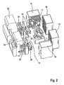
- FIG. 1 Such an arrangement 10 is shown, which essentially consists of a central handling device 11, a device 12 for emptying containers 13, a device 14 for filling containers 13 and four stores 15, 16, 17, 18, the devices 12 and 13 and the memory 15 to 18 are connected by fence elements 19 to form a working space 20 with each other.
- the handling device 11 is disposed within the working space 20 and thus shielded to the outside.
- the working space 20 virtually forms a self-contained cell, within which the handling device 11 can be moved, pivoted or otherwise moved in a plurality of degrees of freedom.
- the number of the level of the container 13 changing devices 12 and 14 for emptying or filling of the container 13 and the number of memory 15 to 18 vary.
- the memory 15 to 18 are formed on their inside, the handling device 11 and the working space 17 facing side closable.
- each memory 15 to 18 associated with a lock element, which may be formed as a roller shutter 21, 22, 23, 24, for example.
- the roller doors 21 to 24 can be opened and closed again to decouple the memory 15 to 18 each from the working space 17.
- the roller shutter 21 is open while the roller doors 22 to 24 are closed.
- the memory 15 to 18 can be coupled to the lock elements or the rolling doors 21 to 24 and decoupled again to replace the memory 15 to 18 if necessary.
- the memory 15 to 18 are fixed to a frame 25, 26, 27, 28 of the rolling doors 21 to 24, in particular during operation of the arrangement 10 a secure To ensure positioning.
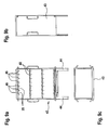
- the fixation is by means of laterally arranged on the frame 25 to 28 plate elements 29, 30 (see, eg FIGS. 5a and 5b ) realized.
- the plate elements 29, 30 are pivotable and allow a fixation both tangentially and perpendicular to the opening of the roller shutter 21 to 24, when the plate elements 29, 30 are pivoted outwardly.
- the devices 12 and 14 are arranged side by side.
- the device 12 for emptying the containers 13 is preceded by an upper belt station 31 and a lower belt station 32.
- the belt station 31 is used to store full containers 13 and supplying them to the device 12.
- the belt station 32 is used for storing the emptied in the device 12 container 13 and discharging the same from the device 12.
- the device 14 for filling the container 13 is analogous with an upper belt station 33 and a lower belt station 34, wherein the belt station 33 for depositing empty containers 13 and supplying them to the device 14 and the belt station 34 for depositing the filled in the device 14 container 13 and discharging them from the device 14 is used.
- the band stations 31 to 34 are all aligned the same way and in such a way that the container 13 are transversely to its longitudinal extent, ie with a broadside ahead, be conveyed.
- Each device 12 and 14 are associated with two memories 15, 16 and 17, 18 in the embodiment shown.
- the memory 15 and 18 are associated with the device 12 and 14 offset by 90 °. This means that the orientation of the containers 13 in the memories 15 and 18 and on the tape stations 31 to 34 is the same.
- the memories 16 and 17 are arranged offset from one another by 90 ° with respect to the memories 15 and 18 and stand on the side of the handling device 11 opposite the devices 12, 14.
- the devices 12 and 14 can each act as so-called "top loaders” with one access be designed for the container 13 from above or as a "front loader” with an access for the container 13 from the front or from the side.
- the memories 15 to 18 are optionally stationary or mobile. As a stationary storage come, for example, solid racks into consideration, the fan 35 for receiving the container 13 have. In another embodiment, not shown fixed container arranged in a rack warehouse, which may be provided with a belt station for providing the container in the gripping region of the handling device 11, for example.
- FIGS. 5 to 10 different mobile memories 15 to 18 are shown.
- FIG. 5a shows a trolley 36, which is also called Schragenwagen.
- the trolley 36 is coupled to a roller shutter 21 in the region of the frame 25 and fixed by the plate elements 29, 30.
- the roller shutter 21 is open (see FIG. 5b ).
- the closed position of the roller shutter 21 results from the FIG. 6b , In the FIG. 6 the trolley 36 is disconnected from the roller shutter 21.
- the roller shutter 21 may be in different states, namely, in a fully closed position according to FIG FIG. 6b , In this position, the trolley 36 can be removed or a new trolley 36 are docked. On the other hand, the roller shutter 21 with its lower edge on the trolley 36 can rest almost flush (see FIG. 5b ), so that the trolley 36 can be processed. In a (not shown) further position, the lower edge of the roller shutter 21 is driven maximum upwards. This position is provided for the interruption of operation of the arrangement 10 in order to be able to enter the cell or the working space 20.
- the trolley 36 (eg according to FIG. 7 ) has three levels 37, 38, 39, on each of which seven compartments 35 are arranged.
- the compartments 35 are provided with a slightly inclined bottom member 40 to prevent falling out of the articles from the partially opened containers 13. Furthermore, the compartments 35 are designed such that the containers 13 arranged in the compartments 35 are accessible to the handling device 11 on the bottom side, that is to say on the side facing the bottom elements 40.
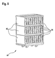
- FIG. 8 shows a container truck 41, which has three containers 42 in the embodiment shown.
- the containers 42 may be fixed or loose on the container car 41.
- the compartments 35 of the container 42 are formed such that the arranged in the compartments 35 container 13 on the bottom side are not accessible to the handling device 11, so that a support of the container 13 is possible only after the partial withdrawal of the same.
- FIGS. 9a and 10a Further embodiments of the memories 15 to 18 are in the Figures 9 and 10 shown.
- the memory shown therein are constructed as container racks 43 similar to the trolley 36, with the difference that instead of the rollers stilts-like feet 44 are provided.
- the feet 44 are formed so high that, for example, a driverless or driverless transport system 45 is movable under the container frame 43 to replace it. From the FIGS. 9a and 10a can be further seen that each of the compartments 35 corresponding to the inclined floor elements 40 guide rails 46 are assigned.
- the handling device 11 is universally designed such that containers 13 can be gripped on a smooth partial surface on the side facing the opened memory 15 to 18. Usually, each container 13 at an end face, which points out of the memory 15 to 18, at least one small attack surface, can attack the gripping elements. In the following, the handling device 11 will be explained in more detail as part of the arrangement 10.
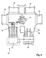
- the handling device 11 essentially has a handling arm 47 and a gripping element 48.
- the handling arm 47 is formed in a conventional manner and movable in several degrees of freedom, both in the linear direction and pivotally.
- the gripping element 48 is arranged movably on a free end 49 of the handling arm 47.
- the gripping element 48 itself consists essentially of a frame-like linear guide 50, a movable support member 51 and a holding member 52 for the container 13. Furthermore, the gripping member 48 has a drive 53 for the linear and pivotal movement of the gripping member 48.
- the linear guide 50 has an approximately U-shaped form.
- a running rail 54 at opposite ends on two frame members 55 and 56 which extend from the running rail 54 downwards.
- the support element 51 is movable on the running rail 54 for gripping, pulling out and pushing in of the containers 13 from a memory 15 to 18 or into a memory 15 to 18.
- the gripping element 48 is designed in such a way that containers 13 can be gripped on smooth partial surfaces on the side pointing out of the memory 15 to 18. These are on the Gripping element 48 elements for pressing and / or pulling the container 13 is arranged.
- the elements for pulling the containers 13 are formed as suction cups 57.
- two suction cups 57 are spaced from each other and arranged one above the other on the support member 51, on the side facing the containers 13 side.
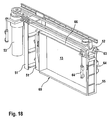
- Each suction cup 57 is associated with a buffer member 58 for pressing the container 13, so that two buffer elements 58 spaced from each other and arranged one above the other on the support member 51 (see, eg FIG. 15 ).
- the suction cups 57 are connected to suction air lines, not shown.
- the buffer elements 58 are made of elastic material almost rigid.
- a bottom of a container 13 supporting support member 59 is arranged on the support member 51.
- the support member 59 for example, fixed and protrudes from the support member 51 in the same direction as the suction cups 57 and buffer members 58.
- the support member 59 may also be designed to be movable or evasive (see, eg FIG. 12b ).
- the movable support member 59 is spring-loaded and retracted in an evasive position against the spring force behind the suction cups 57 and buffer members 58 ( FIG. 12b ). In a support position (see eg Figur13b ), the support member 59 is positioned below the bottom 60 of the container 13.
- At least one sensor element 61 is arranged on the gripping element 48, preferably in the region of the support element 51 on the side facing the containers 13, at least one sensor element 61 is arranged. Preferably, several, in particular three sensor elements 61 are provided. The sensor elements 61 are used in particular for detecting the position of the container floor level and the container rear wall level. Furthermore, at least one monitoring means, preferably a camera 62, is arranged on gripper element 48. The camera 62 is arranged on the holding element 52, in such a way that an inspection is ensured in the container 13 for purposes of monitoring the content and the state of the content (see, for example FIG. 16 ).
- the holding element 52 comprises a pressure plate 63 which is movable by means of pressure cylinders 64.
- the pressure plate 63 serves to fix the container 13 during transport thereof.
- the container 13 is clamped during transport between the pressure plate 63 and a web 65, wherein the container 13 is additionally supported on the support element 59 on the side opposite the web 65.
- the pressure plate 63 is in operative connection with a further plate 66, which is also actuated by the pressure cylinder 64.
- the plate 66 serves to fix the articles within the container 13.
- a plurality of cameras 67 are arranged, which serve to detect unwanted movements of the articles within the container 13 and the optical quality control.
- the cameras 67 are arranged above the container 13 to be transported, so that an inspection can be carried out from above.
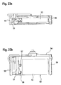
- FIG. 14 shows the search travel of the gripping element 48 in front of a compartment 35 with a container 13.
- the sensor elements 61 the positions of the container bottom level and the container rear wall level are determined (see also FIG. 15 ).
- the container 13 is already partially pulled out of the compartment 35 and is only on the bottom element 40 of the compartment 35 with the distal end.
- this is supported on the web 65 and guided by the frame member 56 (In FIG. 16 if the frame element 56 has been omitted for the sake of clarity).
- the position of the articles in the container 13 or the complete emptying of the container 13 is checked by the camera 62.
- the container 13 is positioned by its own bottom 60 during transport.
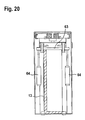
- the rear side wall is pressed by a plate between lateral guides. (see also the cross section according to FIG. 20 ).
- the front side wall is held by the suction cups 57 and supported by the fixed support member 59 from below.
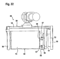
- FIG. 21 shows the gripping member 48 with the fixed support member 59 in the transport state.
- the gripping element 48 As soon as the gripping element 48 has reached its position for dispensing the container 13 above the belt station 31, the container 13 is set down and the gripper element 48 is opened. For this purpose, the pressure plate 63 is released and lifted slightly.
- the container 13 stands on the belt station 31.
- the support element 51 moves away from the container side wall and the handling device 11 initiates the opposite movement, but to a lesser extent than the support element 51, so that the gripping element 48 is opened. Now, the handling device 11 can pivot and record another container 13 in reverse order.
Landscapes
- Engineering & Computer Science (AREA)
- Mechanical Engineering (AREA)
- Specific Conveyance Elements (AREA)
- Warehouses Or Storage Devices (AREA)
- Auxiliary Devices For And Details Of Packaging Control (AREA)
- Filling Of Jars Or Cans And Processes For Cleaning And Sealing Jars (AREA)
- Container Filling Or Packaging Operations (AREA)
- Basic Packing Technique (AREA)
- Filling Or Emptying Of Bunkers, Hoppers, And Tanks (AREA)
Claims (11)
- Ensemble servant à remplir et/ou à vider des contenants (13) remplis d'articles et/ou à remplir, comprenant sensiblement au moins un dispositif de manutention (11) pour transporter des contenants (13) remplis et/ou à remplir entre un réservoir (15, 16, 17, 18) et un dispositif (12, 14) faisant varier le niveau de remplissage des contenants (13), au moins un dispositif (12, 14) faisant varier le niveau de remplissage des contenants (13), ainsi qu'au moins un réservoir (15 à 18) destiné à recevoir des contenants (13) remplis et/ou à remplir, caractérisé en ce que l'ensemble (10) est réalisé en tant qu'ensemble fermé, de façon telle que le dispositif de manutention (11) est entouré à la manière d'une cellule par ledit au moins un dispositif (12, 14) faisant varier le niveau de remplissage des contenants ainsi que par ledit au moins un réservoir (15 à 18), chaque réservoir (15 à 18) étant associé à un élément de sas à ouvrir ou à fermer sélectivement, de façon telle que le ou chaque réservoir (15 à 18) peut être fermé sur le côté orienté vers l'intérieur et tourné vers le dispositif de manutention (11).
- Ensemble selon la revendication 1, caractérisé en ce que l'ensemble (10) présente, outre quatre réservoirs (15 à 18), un dispositif (12) pour vider des contenants (13) et un dispositif (14) pour remplir des contenants (13), lesquels sont reliés par des éléments de clôture (19) pour constituer une cellule formant un espace de travail (20) circulaire, le dispositif de manutention (11) étant disposé dans l'espace de travail (20).
- Ensemble selon la revendication 1, caractérisé en ce que les réservoirs (15 à 18) peuvent être accouplés à et désaccouplés de l'élément de sas.
- Ensemble selon l'une des revendications 1 à 3, caractérisé en ce que les éléments de sas sont conçus sous forme de portes roulantes (21, 22,23,24).
- Ensemble selon la revendication 4, caractérisé en ce que les réservoirs (15 à 18) peuvent être fixés sur des bâtis (25, 26, 27, 28) des portes roulantes (21 à 24).
- Ensemble selon l'une des revendications 1 à 5, caractérisé en ce que les réservoirs (15 à 18) sont conçus de manière fixe ou mobile.
- Ensemble selon l'une des revendications 1 à 6, caractérisé en ce que les réservoirs (15 à 18) présentent au moins un compartiment (35), de préférence plusieurs compartiments (35) pour recevoir les contenants (13).
- Ensemble selon l'une des revendications 1 à 7, caractérisé en ce que les réservoirs (15 à 18) sont conçus sous forme de chariots roulants (36).
- Ensemble selon l'une des revendications 1 à 8, caractérisé en ce que les réservoirs (15 à 18) sont conçus sous forme de chariots porte-conteneurs (41).
- Ensemble selon la revendication 8 ou 9, caractérisé en ce que les chariots roulants (36) ou chariots porte-conteneurs (41) peuvent être fixés dans la région des portes roulantes (21 à 24) au moyen d'éléments en forme de plaques (29, 30) disposés à pivotement sur le bâti (25 à 28).
- Ensemble selon l'une des revendications 1 à 10, caractérisé en ce que le dispositif de manutention (11) est de type universel, conçu de façon que des contenants (13) puissent être saisis au niveau d'une surface partielle lisse sur le côté orienté vers l'extérieur du réservoir (15 à 18) ouvert.
Priority Applications (3)
| Application Number | Priority Date | Filing Date | Title |
|---|---|---|---|
| PL09075225T PL2100834T3 (pl) | 2003-11-25 | 2004-10-28 | Urządzenie manipulacyjne do transportowania pojemników napełnionych i/lub przeznaczonych do napełnienia artykułami |
| PL04820389T PL1704105T3 (pl) | 2003-11-25 | 2004-10-28 | Układ do napełniania i/lub opróżniania napełnionych i/lub przeznaczonych do napełniania wyrobami pojemników oraz urządzenie manipulacyjne do transportowania pojemników |
| EP09075225A EP2100834B9 (fr) | 2003-11-25 | 2004-10-28 | Dispositif de manipulation destiné au transport de récipients remplis et/ou devant être remplis d'articles |
Applications Claiming Priority (2)
| Application Number | Priority Date | Filing Date | Title |
|---|---|---|---|
| DE10355876A DE10355876A1 (de) | 2003-11-25 | 2003-11-25 | Anordnung zum Befüllen und/oder Entleeren von mit Artikeln gefüllten und/oder zu befüllenden Behältern sowie Handhabungsvorrichtung zum Transportieren der Behälter |
| PCT/EP2004/012350 WO2005058077A2 (fr) | 2003-11-25 | 2004-10-28 | Ensemble servant a remplir et/ou a vider des contenants a remplir et/ou remplis d'articles et dispositif de manipulation pour le transport desdits contenants |
Related Child Applications (2)
| Application Number | Title | Priority Date | Filing Date |
|---|---|---|---|
| EP09075225A Division EP2100834B9 (fr) | 2003-11-25 | 2004-10-28 | Dispositif de manipulation destiné au transport de récipients remplis et/ou devant être remplis d'articles |
| EP09075225.4 Division-Into | 2009-05-08 |
Publications (2)
| Publication Number | Publication Date |
|---|---|
| EP1704105A2 EP1704105A2 (fr) | 2006-09-27 |
| EP1704105B1 true EP1704105B1 (fr) | 2011-11-30 |
Family
ID=34683272
Family Applications (2)
| Application Number | Title | Priority Date | Filing Date |
|---|---|---|---|
| EP09075225A Revoked EP2100834B9 (fr) | 2003-11-25 | 2004-10-28 | Dispositif de manipulation destiné au transport de récipients remplis et/ou devant être remplis d'articles |
| EP04820389A Not-in-force EP1704105B1 (fr) | 2003-11-25 | 2004-10-28 | Ensemble servant a remplir et/ou a vider des contenants a remplir et/ou remplis d'articles et dispositif de manipulation pour le transport desdits contenants |
Family Applications Before (1)
| Application Number | Title | Priority Date | Filing Date |
|---|---|---|---|
| EP09075225A Revoked EP2100834B9 (fr) | 2003-11-25 | 2004-10-28 | Dispositif de manipulation destiné au transport de récipients remplis et/ou devant être remplis d'articles |
Country Status (8)
| Country | Link |
|---|---|
| US (1) | US7909557B2 (fr) |
| EP (2) | EP2100834B9 (fr) |
| JP (1) | JP4435172B2 (fr) |
| CN (1) | CN1882485B (fr) |
| AT (1) | ATE535477T1 (fr) |
| DE (1) | DE10355876A1 (fr) |
| PL (2) | PL2100834T3 (fr) |
| WO (1) | WO2005058077A2 (fr) |
Families Citing this family (9)
| Publication number | Priority date | Publication date | Assignee | Title |
|---|---|---|---|---|
| ITBO20050529A1 (it) * | 2005-08-09 | 2005-11-08 | Gd Spa | Dispositivo e metodo per immagazzinare e rendere disponibili articoli da fumo semilavorati |
| US8186929B2 (en) * | 2008-08-04 | 2012-05-29 | Quantum Corporation | High density variable access storage library |
| DE102008039974A1 (de) * | 2008-08-27 | 2010-03-04 | Klaus Knaust | Rahmensortieranlage mit Schwenkaufrichter und Zwischenfahrgestell |
| IT1394375B1 (it) * | 2009-06-22 | 2012-06-15 | Gd Spa | Dispositivo per l'approvvigionamento di materiale ad una macchina per la realizzazione di articoli da fumo. |
| DE102011010257A1 (de) * | 2011-01-26 | 2012-07-26 | Hauni Maschinenbau Ag | Anordnung und Verfahren zum Produzieren und Speichern stabförmiger Halbfertigprodukte der Tabak verarbeitenden Industrie |
| CN103010643B (zh) * | 2013-01-05 | 2014-12-10 | 浙江中烟工业有限责任公司 | 一种可自动加去盖的烟丝箱高架库系统及加去盖方法 |
| EP3269264A1 (fr) * | 2016-07-13 | 2018-01-17 | International Tobacco Machinery Poland Sp. z o.o. | Procédé et appareil permettant de vider divers types de récipients remplis d'articles en forme de tige de l'industrie du tabac et unité de conversion destinée à changer la configuration du récipients |
| CN111498485B (zh) * | 2019-01-30 | 2023-06-27 | 百特国际有限公司 | 医疗流体产品传送系统和方法 |
| CN115338210B (zh) * | 2022-07-29 | 2023-11-14 | 浙江世宏实业有限公司 | 一种自动清屑系统 |
Family Cites Families (35)
| Publication number | Priority date | Publication date | Assignee | Title |
|---|---|---|---|---|
| DE1632196A1 (de) * | 1967-03-25 | 1970-05-14 | Hauni Werke Koerber & Co Kg | Zigarettenschragenfoerderanlage |
| US3912061A (en) * | 1973-10-23 | 1975-10-14 | Jr Joseph E Foster | Safety fence |
| DE3332196C2 (de) * | 1983-09-07 | 1985-08-01 | Hermann Spicher GmbH, 5000 Köln | Vorrichtung zur automatischen Entnahme von Gegenständen aus Behältern |
| FR2553864B3 (fr) | 1983-10-20 | 1986-01-03 | Renault | Dispositif de securite pour la protection du personnel present dans la zone de travail d'un robot |
| US4789295A (en) * | 1985-02-26 | 1988-12-06 | International Business Machines Corp. | Article manipulator for robot |
| JPS61206709A (ja) * | 1985-03-07 | 1986-09-13 | Motoda Electronics Co Ltd | トレ−配送装置 |
| DE3532305A1 (de) | 1985-09-11 | 1987-03-12 | Messer Griesheim Gmbh | Fertigungs- und/oder montagezelle fuer werkstuecke |
| GB8602105D0 (en) * | 1986-01-29 | 1986-03-05 | Precision Eng Products Suffolk | Automatic article handling methods |
| US4892453A (en) | 1986-07-17 | 1990-01-09 | Korber Ag | Apparatus for manipulating empty and filled trays for cigarettes and like rod-shaped articles between making and processing machines |
| JPS63192370A (ja) * | 1987-02-05 | 1988-08-09 | 日本たばこ産業株式会社 | 棒状物の充填装置 |
| SE460530C (sv) | 1988-09-15 | 1995-06-22 | Transman Ab | Anläggning för robotoperationer |
| DE3835032A1 (de) | 1988-10-14 | 1990-04-19 | Niepmann Traylift Transport | Verfahren und vorrichtung zum entstapeln von blockweise auf paletten gestapelten zuschnitten |
| DE3917097C2 (de) | 1989-05-26 | 1998-07-02 | Hauni Werke Koerber & Co Kg | Behälterfördervorrichtung |
| FR2660005A1 (fr) | 1990-03-23 | 1991-09-27 | Tmf | Cloture pour enceinte de securite. |
| JP2669714B2 (ja) * | 1990-11-19 | 1997-10-29 | 株式会社ピーエフユー | 部品供給装置 |
| IT1245912B (it) * | 1991-05-22 | 1994-10-25 | Gd Spa | Impianto per la pallettizzazione selettiva di articoli di diverse caratteristiche. |
| JP3185595B2 (ja) | 1995-04-03 | 2001-07-11 | 株式会社ダイフク | 基板仕分け装置を備えた荷保管設備 |
| DE19622995A1 (de) * | 1996-06-08 | 1997-12-11 | Hauni Maschinenbau Ag | Verfahren und Vorrichtung zur Handhabung von Zigarettenschragen |
| DE19815434A1 (de) * | 1998-04-07 | 1999-10-14 | Focke & Co | Hubvorrichtung (Palettierer) mit Schwenkarm |
| US6204469B1 (en) * | 1999-03-04 | 2001-03-20 | Honda Giken Kogyo Kabushiki Kaisha | Laser welding system |
| US6176699B1 (en) * | 1999-04-28 | 2001-01-23 | Walbro Corporation | Parison handling device |
| DE19959061A1 (de) * | 1999-12-08 | 2001-06-13 | Hauni Maschinenbau Ag | Verfahren zum Fördern von stabförmigen Artikeln und Behälterfördervorrichtung |
| DE19959285B4 (de) | 1999-12-09 | 2008-01-31 | J. Schmalz Gmbh | Vakuum-Greifsystem zum Greifen eines Objekts und Handhabungsgerät zum Handhaben eines Objekts mit Hilfe eines Vakuum-Greifsystems |
| DE20003638U1 (de) * | 2000-02-29 | 2000-05-25 | D & T Engineering Gmbh | Roboterzelle für Handhabungseinrichtungen |
| AUPQ780900A0 (en) * | 2000-05-29 | 2000-06-22 | Becfab Equipment Pty Ltd | Article transfer apparatus |
| US6419438B1 (en) * | 2000-11-28 | 2002-07-16 | Asyst Technologies, Inc. | FIMS interface without alignment pins |
| US6892890B2 (en) * | 2001-01-16 | 2005-05-17 | Abb Automation, Inc. | Dynamic sortation of items in a containerization system |
| DE20101442U1 (de) | 2001-01-27 | 2001-05-10 | Ludwig Schleicher Gmbh Maschb | Bearbeitungsanlage mit einem Bearbeitungsroboter |
| US6585470B2 (en) * | 2001-06-19 | 2003-07-01 | Brooks Automation, Inc. | System for transporting substrates |
| JP2003072916A (ja) * | 2001-08-30 | 2003-03-12 | Sony Corp | 保管装置 |
| ITBO20010657A1 (it) * | 2001-10-31 | 2003-05-01 | Gd Spa | Metodo ed apparecchiatura di alimentazione di elementi allungati |
| JP2003193777A (ja) * | 2001-12-26 | 2003-07-09 | Erecta International Corp | 運搬用台車のシャッターの施錠構造 |
| DE50306628D1 (de) | 2002-06-21 | 2007-04-12 | Abb Patent Gmbh | Roboteranlage mit einem Roboter mit einer Schutzvorrichtung |
| DE102004041821A1 (de) * | 2004-08-27 | 2006-03-16 | Abb Research Ltd. | Vorrichtung und Verfahren zur Sicherung eines maschinell gesteuerten Handhabungsgerätes |
| US7322083B2 (en) * | 2005-11-30 | 2008-01-29 | Nokia Corporation | Manufacturing system architecture for tools |
-
2003
- 2003-11-25 DE DE10355876A patent/DE10355876A1/de not_active Ceased
-
2004
- 2004-10-28 US US10/580,031 patent/US7909557B2/en not_active Expired - Fee Related
- 2004-10-28 CN CN2004800344579A patent/CN1882485B/zh not_active Expired - Fee Related
- 2004-10-28 AT AT04820389T patent/ATE535477T1/de active
- 2004-10-28 PL PL09075225T patent/PL2100834T3/pl unknown
- 2004-10-28 WO PCT/EP2004/012350 patent/WO2005058077A2/fr active Application Filing
- 2004-10-28 PL PL04820389T patent/PL1704105T3/pl unknown
- 2004-10-28 EP EP09075225A patent/EP2100834B9/fr not_active Revoked
- 2004-10-28 JP JP2006540223A patent/JP4435172B2/ja not_active Expired - Fee Related
- 2004-10-28 EP EP04820389A patent/EP1704105B1/fr not_active Not-in-force
Also Published As
| Publication number | Publication date |
|---|---|
| CN1882485A (zh) | 2006-12-20 |
| JP4435172B2 (ja) | 2010-03-17 |
| WO2005058077A2 (fr) | 2005-06-30 |
| US7909557B2 (en) | 2011-03-22 |
| ATE535477T1 (de) | 2011-12-15 |
| EP1704105A2 (fr) | 2006-09-27 |
| DE10355876A1 (de) | 2005-07-28 |
| EP2100834B1 (fr) | 2012-08-15 |
| EP2100834A1 (fr) | 2009-09-16 |
| JP2007512198A (ja) | 2007-05-17 |
| WO2005058077A3 (fr) | 2005-09-22 |
| US20070110546A1 (en) | 2007-05-17 |
| PL1704105T3 (pl) | 2012-04-30 |
| EP2100834B9 (fr) | 2013-02-27 |
| CN1882485B (zh) | 2010-11-03 |
| PL2100834T3 (pl) | 2013-01-31 |
Similar Documents
| Publication | Publication Date | Title |
|---|---|---|
| EP3106241B1 (fr) | Machine-outil et procédé destinés a l'évacuation de parties d'une pièce à usiner | |
| EP1980490B1 (fr) | Installation de chargement de bagages dans un conteneur | |
| DE4117434A1 (de) | Verfahren und vorrichtung zum stapeln | |
| DE102011053602A1 (de) | Schragen-Handhabungshilfe für einen Schragen zum Transportieren und/oder Bevorraten von stabförmigen Artikeln der Tabak verarbeitenden Industrie, Schragen mit einer solchen Schragen-Handhabungshilfe, Schragen-Entleermagazin zum Entleeren solcher Schragen sowie Schragenentleerer mit einem solchen Schragen-Entleermagazin | |
| EP2130445B9 (fr) | Dispositif et procédé de vidage successif de récipients remplis de produits en forme de tiges | |
| EP1704105B1 (fr) | Ensemble servant a remplir et/ou a vider des contenants a remplir et/ou remplis d'articles et dispositif de manipulation pour le transport desdits contenants | |
| DE10018385A1 (de) | Verfahren und Vorrichtung zum selbsttätigen Be- und Entladen von Stückgut | |
| DE102005002532A1 (de) | Vorrichtung und Verfahren zum automatisierten und zeitgleichen Bereitstellen und Wechseln von mindestens zwei Rollen aus Papierbahnen oder dergleichen für einen nachgeordneten Formatschneider | |
| DE102015007861A1 (de) | Vorrichtung zum Transport von Ladungsträgern, Transportwagen und Transportvorrichtung | |
| DE19948574A1 (de) | Einrichtung zum Vereinzeln und Ausschleusen von in einer Reihe auf einer Rollenbahn abgelegten Stückgütern | |
| EP2596708B1 (fr) | Agencement de manipulation de récipients de transport pour des articles en forme de tige de l'industrie de traitement du tabac et procédé destiné à modifier le niveau de remplissage de récipients de transport | |
| DE3005529C2 (de) | Palettiervorrichtung | |
| EP2759216A1 (fr) | Dispositif de vidage de casiers et procédé de vidage automatique de casiers remplis d'articles en forme de tiges dans une machine de production de l'industrie de traitement du tabac, et système de production doté d'une machine de production et d'au moins deux dispositifs de vidage de casiers | |
| DE3822363C2 (fr) | ||
| EP1862405B1 (fr) | Procédé destiné à saisir une marchandise à l'aide d'éléments de préhension dans un dispositif de stockage et de déstockage et dispositif correspondant | |
| EP1690458A1 (fr) | Dispositif de manutention de conteneurs de l'industrie de tabac | |
| DE19519615C2 (de) | Vorrichtung für das Stapeln von Profilen | |
| DE19945386B4 (de) | Verfahren und Vorrichtung zum Verpacken von Rollenware, insbesondere Wickelrollen aus Kunststofffolie | |
| DE2604973C3 (de) | Flaschenauspackmaschine | |
| EP1557382B1 (fr) | Dispositif pour le prélèvement de palettes vides | |
| DE1223306B (de) | Hublader mit Lastschieber | |
| EP0860360B1 (fr) | Machine de cerclage | |
| DE3327365A1 (de) | Vorrichtung zum fuellen von containern | |
| DE102012202756B4 (de) | Vorrichtung zur Handhabung von Formteilen aus thermoplastischem Kunststoff | |
| DE202010003868U1 (de) | Vorrichtung zur Beschickung von Behältern, insbesondere Containern |
Legal Events
| Date | Code | Title | Description |
|---|---|---|---|
| PUAI | Public reference made under article 153(3) epc to a published international application that has entered the european phase |
Free format text: ORIGINAL CODE: 0009012 |
|
| 17P | Request for examination filed |
Effective date: 20060623 |
|
| AK | Designated contracting states |
Kind code of ref document: A2 Designated state(s): AT BE BG CH CY CZ DE DK EE ES FI FR GB GR HU IE IT LI LU MC NL PL PT RO SE SI SK TR |
|
| DAX | Request for extension of the european patent (deleted) | ||
| 17Q | First examination report despatched |
Effective date: 20070625 |
|
| TPAC | Observations filed by third parties |
Free format text: ORIGINAL CODE: EPIDOSNTIPA |
|
| GRAP | Despatch of communication of intention to grant a patent |
Free format text: ORIGINAL CODE: EPIDOSNIGR1 |
|
| GRAS | Grant fee paid |
Free format text: ORIGINAL CODE: EPIDOSNIGR3 |
|
| GRAA | (expected) grant |
Free format text: ORIGINAL CODE: 0009210 |
|
| AK | Designated contracting states |
Kind code of ref document: B1 Designated state(s): AT BE BG CH CY CZ DE DK EE ES FI FR GB GR HU IE IT LI LU MC NL PL PT RO SE SI SK TR |
|
| REG | Reference to a national code |
Ref country code: GB Ref legal event code: FG4D Free format text: NOT ENGLISH Ref country code: CH Ref legal event code: EP |
|
| REG | Reference to a national code |
Ref country code: IE Ref legal event code: FG4D Free format text: LANGUAGE OF EP DOCUMENT: GERMAN |
|
| REG | Reference to a national code |
Ref country code: DE Ref legal event code: R096 Ref document number: 502004013121 Country of ref document: DE Effective date: 20120119 |
|
| REG | Reference to a national code |
Ref country code: NL Ref legal event code: T3 |
|
| REG | Reference to a national code |
Ref country code: PL Ref legal event code: T3 |
|
| PG25 | Lapsed in a contracting state [announced via postgrant information from national office to epo] |
Ref country code: SI Free format text: LAPSE BECAUSE OF FAILURE TO SUBMIT A TRANSLATION OF THE DESCRIPTION OR TO PAY THE FEE WITHIN THE PRESCRIBED TIME-LIMIT Effective date: 20111130 Ref country code: SE Free format text: LAPSE BECAUSE OF FAILURE TO SUBMIT A TRANSLATION OF THE DESCRIPTION OR TO PAY THE FEE WITHIN THE PRESCRIBED TIME-LIMIT Effective date: 20111130 Ref country code: GR Free format text: LAPSE BECAUSE OF FAILURE TO SUBMIT A TRANSLATION OF THE DESCRIPTION OR TO PAY THE FEE WITHIN THE PRESCRIBED TIME-LIMIT Effective date: 20120301 Ref country code: PT Free format text: LAPSE BECAUSE OF FAILURE TO SUBMIT A TRANSLATION OF THE DESCRIPTION OR TO PAY THE FEE WITHIN THE PRESCRIBED TIME-LIMIT Effective date: 20120330 |
|
| REG | Reference to a national code |
Ref country code: IE Ref legal event code: FD4D |
|
| PG25 | Lapsed in a contracting state [announced via postgrant information from national office to epo] |
Ref country code: CY Free format text: LAPSE BECAUSE OF FAILURE TO SUBMIT A TRANSLATION OF THE DESCRIPTION OR TO PAY THE FEE WITHIN THE PRESCRIBED TIME-LIMIT Effective date: 20111130 |
|
| PG25 | Lapsed in a contracting state [announced via postgrant information from national office to epo] |
Ref country code: CZ Free format text: LAPSE BECAUSE OF FAILURE TO SUBMIT A TRANSLATION OF THE DESCRIPTION OR TO PAY THE FEE WITHIN THE PRESCRIBED TIME-LIMIT Effective date: 20111130 Ref country code: EE Free format text: LAPSE BECAUSE OF FAILURE TO SUBMIT A TRANSLATION OF THE DESCRIPTION OR TO PAY THE FEE WITHIN THE PRESCRIBED TIME-LIMIT Effective date: 20111130 Ref country code: IE Free format text: LAPSE BECAUSE OF FAILURE TO SUBMIT A TRANSLATION OF THE DESCRIPTION OR TO PAY THE FEE WITHIN THE PRESCRIBED TIME-LIMIT Effective date: 20111130 Ref country code: DK Free format text: LAPSE BECAUSE OF FAILURE TO SUBMIT A TRANSLATION OF THE DESCRIPTION OR TO PAY THE FEE WITHIN THE PRESCRIBED TIME-LIMIT Effective date: 20111130 Ref country code: BG Free format text: LAPSE BECAUSE OF FAILURE TO SUBMIT A TRANSLATION OF THE DESCRIPTION OR TO PAY THE FEE WITHIN THE PRESCRIBED TIME-LIMIT Effective date: 20120229 Ref country code: SK Free format text: LAPSE BECAUSE OF FAILURE TO SUBMIT A TRANSLATION OF THE DESCRIPTION OR TO PAY THE FEE WITHIN THE PRESCRIBED TIME-LIMIT Effective date: 20111130 |
|
| PG25 | Lapsed in a contracting state [announced via postgrant information from national office to epo] |
Ref country code: RO Free format text: LAPSE BECAUSE OF FAILURE TO SUBMIT A TRANSLATION OF THE DESCRIPTION OR TO PAY THE FEE WITHIN THE PRESCRIBED TIME-LIMIT Effective date: 20111130 |
|
| PLBE | No opposition filed within time limit |
Free format text: ORIGINAL CODE: 0009261 |
|
| STAA | Information on the status of an ep patent application or granted ep patent |
Free format text: STATUS: NO OPPOSITION FILED WITHIN TIME LIMIT |
|
| 26N | No opposition filed |
Effective date: 20120831 |
|
| PGFP | Annual fee paid to national office [announced via postgrant information from national office to epo] |
Ref country code: PL Payment date: 20120928 Year of fee payment: 9 |
|
| REG | Reference to a national code |
Ref country code: DE Ref legal event code: R097 Ref document number: 502004013121 Country of ref document: DE Effective date: 20120831 |
|
| BERE | Be: lapsed |
Owner name: HAUNI MASCHINENBAU A.G. Effective date: 20121031 |
|
| PG25 | Lapsed in a contracting state [announced via postgrant information from national office to epo] |
Ref country code: ES Free format text: LAPSE BECAUSE OF FAILURE TO SUBMIT A TRANSLATION OF THE DESCRIPTION OR TO PAY THE FEE WITHIN THE PRESCRIBED TIME-LIMIT Effective date: 20120311 |
|
| REG | Reference to a national code |
Ref country code: NL Ref legal event code: V1 Effective date: 20130501 |
|
| PG25 | Lapsed in a contracting state [announced via postgrant information from national office to epo] |
Ref country code: MC Free format text: LAPSE BECAUSE OF NON-PAYMENT OF DUE FEES Effective date: 20121031 |
|
| REG | Reference to a national code |
Ref country code: CH Ref legal event code: PL |
|
| GBPC | Gb: european patent ceased through non-payment of renewal fee |
Effective date: 20121028 |
|
| PG25 | Lapsed in a contracting state [announced via postgrant information from national office to epo] |
Ref country code: FI Free format text: LAPSE BECAUSE OF FAILURE TO SUBMIT A TRANSLATION OF THE DESCRIPTION OR TO PAY THE FEE WITHIN THE PRESCRIBED TIME-LIMIT Effective date: 20111130 |
|
| REG | Reference to a national code |
Ref country code: FR Ref legal event code: ST Effective date: 20130628 |
|
| PG25 | Lapsed in a contracting state [announced via postgrant information from national office to epo] |
Ref country code: GB Free format text: LAPSE BECAUSE OF NON-PAYMENT OF DUE FEES Effective date: 20121028 Ref country code: CH Free format text: LAPSE BECAUSE OF NON-PAYMENT OF DUE FEES Effective date: 20121031 Ref country code: DE Free format text: LAPSE BECAUSE OF NON-PAYMENT OF DUE FEES Effective date: 20130501 Ref country code: LI Free format text: LAPSE BECAUSE OF NON-PAYMENT OF DUE FEES Effective date: 20121031 Ref country code: BE Free format text: LAPSE BECAUSE OF NON-PAYMENT OF DUE FEES Effective date: 20121031 |
|
| REG | Reference to a national code |
Ref country code: DE Ref legal event code: R119 Ref document number: 502004013121 Country of ref document: DE Effective date: 20130501 |
|
| PG25 | Lapsed in a contracting state [announced via postgrant information from national office to epo] |
Ref country code: NL Free format text: LAPSE BECAUSE OF NON-PAYMENT OF DUE FEES Effective date: 20130501 Ref country code: IT Free format text: LAPSE BECAUSE OF NON-PAYMENT OF DUE FEES Effective date: 20121028 Ref country code: FR Free format text: LAPSE BECAUSE OF NON-PAYMENT OF DUE FEES Effective date: 20121031 |
|
| REG | Reference to a national code |
Ref country code: AT Ref legal event code: MM01 Ref document number: 535477 Country of ref document: AT Kind code of ref document: T Effective date: 20121031 |
|
| PG25 | Lapsed in a contracting state [announced via postgrant information from national office to epo] |
Ref country code: AT Free format text: LAPSE BECAUSE OF NON-PAYMENT OF DUE FEES Effective date: 20121031 |
|
| PG25 | Lapsed in a contracting state [announced via postgrant information from national office to epo] |
Ref country code: TR Free format text: LAPSE BECAUSE OF FAILURE TO SUBMIT A TRANSLATION OF THE DESCRIPTION OR TO PAY THE FEE WITHIN THE PRESCRIBED TIME-LIMIT Effective date: 20111130 |
|
| PG25 | Lapsed in a contracting state [announced via postgrant information from national office to epo] |
Ref country code: LU Free format text: LAPSE BECAUSE OF NON-PAYMENT OF DUE FEES Effective date: 20121028 |
|
| PG25 | Lapsed in a contracting state [announced via postgrant information from national office to epo] |
Ref country code: HU Free format text: LAPSE BECAUSE OF FAILURE TO SUBMIT A TRANSLATION OF THE DESCRIPTION OR TO PAY THE FEE WITHIN THE PRESCRIBED TIME-LIMIT Effective date: 20041028 |
|
| REG | Reference to a national code |
Ref country code: PL Ref legal event code: LAPE |
|
| PG25 | Lapsed in a contracting state [announced via postgrant information from national office to epo] |
Ref country code: PL Free format text: LAPSE BECAUSE OF NON-PAYMENT OF DUE FEES Effective date: 20131028 |