EP1703022B1 - Barrière de sécurité perfectionnée - Google Patents
Barrière de sécurité perfectionnée Download PDFInfo
- Publication number
- EP1703022B1 EP1703022B1 EP06111096.1A EP06111096A EP1703022B1 EP 1703022 B1 EP1703022 B1 EP 1703022B1 EP 06111096 A EP06111096 A EP 06111096A EP 1703022 B1 EP1703022 B1 EP 1703022B1
- Authority
- EP
- European Patent Office
- Prior art keywords
- rail
- fact
- gate according
- support assembly
- support
- Prior art date
- Legal status (The legal status is an assumption and is not a legal conclusion. Google has not performed a legal analysis and makes no representation as to the accuracy of the status listed.)
- Active
Links
- 238000001514 detection method Methods 0.000 claims description 3
- 238000006073 displacement reaction Methods 0.000 claims description 3
- 239000002131 composite material Substances 0.000 claims description 2
- 230000006866 deterioration Effects 0.000 claims description 2
- 230000004888 barrier function Effects 0.000 description 36
- 230000000670 limiting effect Effects 0.000 description 6
- 230000035939 shock Effects 0.000 description 4
- 238000012423 maintenance Methods 0.000 description 3
- 125000006850 spacer group Chemical group 0.000 description 3
- 229910052751 metal Inorganic materials 0.000 description 2
- 239000002184 metal Substances 0.000 description 2
- 230000036961 partial effect Effects 0.000 description 2
- 229910001220 stainless steel Inorganic materials 0.000 description 2
- 239000010935 stainless steel Substances 0.000 description 2
- 239000012815 thermoplastic material Substances 0.000 description 2
- 229910052782 aluminium Inorganic materials 0.000 description 1
- XAGFODPZIPBFFR-UHFFFAOYSA-N aluminium Chemical compound [Al] XAGFODPZIPBFFR-UHFFFAOYSA-N 0.000 description 1
- 230000000295 complement effect Effects 0.000 description 1
- 230000006378 damage Effects 0.000 description 1
- 238000013016 damping Methods 0.000 description 1
- 230000000694 effects Effects 0.000 description 1
- 230000001939 inductive effect Effects 0.000 description 1
- 238000009434 installation Methods 0.000 description 1
- 238000009527 percussion Methods 0.000 description 1
- 230000001681 protective effect Effects 0.000 description 1
- 230000000717 retained effect Effects 0.000 description 1
- 230000002441 reversible effect Effects 0.000 description 1
Images


Classifications
-
- E—FIXED CONSTRUCTIONS
- E01—CONSTRUCTION OF ROADS, RAILWAYS, OR BRIDGES
- E01F—ADDITIONAL WORK, SUCH AS EQUIPPING ROADS OR THE CONSTRUCTION OF PLATFORMS, HELICOPTER LANDING STAGES, SIGNS, SNOW FENCES, OR THE LIKE
- E01F13/00—Arrangements for obstructing or restricting traffic, e.g. gates, barricades ; Preventing passage of vehicles of selected category or dimensions
- E01F13/04—Arrangements for obstructing or restricting traffic, e.g. gates, barricades ; Preventing passage of vehicles of selected category or dimensions movable to allow or prevent passage
- E01F13/06—Arrangements for obstructing or restricting traffic, e.g. gates, barricades ; Preventing passage of vehicles of selected category or dimensions movable to allow or prevent passage by swinging into open position about a vertical or horizontal axis parallel to the road direction, i.e. swinging gates
Definitions
- the present invention relates to the field of barriers for controlling the passage on a taxiway.
- the present invention can find many applications.
- the barriers in accordance with the present invention may, in particular, be used on motorway toll stations, parking access points, etc.
- the known barriers generally comprise a rail associated with a drive system adapted to selectively move the rail between a horizontal rest position, transverse to the traffic lane, suitable for preventing the passage, and a temporary position releasing said lane for allow passage through the taxiway when authorized access is detected.
- one of the problems badly solved by the existing barriers according to the state of the art is that of the rapid implementation after an accidental shock, for example when a vehicle hits the rail of a safety barrier .
- a device when the vehicle hits the rail of a safety barrier, a device is provided so that the rail exits the vehicle path by rotating about a vertical axis during its relative movement relative to the vehicle. crew support.
- These barriers have the disadvantage of requiring a manual reset by the staff, for example the public, which requires him to leave his local and come on the road, at the risk of being struck by the next vehicle.
- the document FR-A-2585064 describes an entry or exit barrier device in a fleet of automobiles.
- This device comprises four main parts: a first part intended to be fixed on a drive means, a first intermediate main part hinged about a horizontal axis on the aforesaid support piece and immobilized thereon by a first latch system ball, a second intermediate main part articulated around a vertical axis on the first intermediate main part and immobilized in the rest position thereon by a second ball catch and a main part forming a smooth door articulated on the second main part intermediate about a vertical axis and immobilized thereon by a third latch system.
- the first intermediate main piece When an attempt is made to move the beam in a vertical position, the first intermediate main piece is disengaged from the support piece by the first ball catch and pivots about the horizontal axis.
- the smooth door part rotates relative to the second main intermediate part or the second intermediate main part rotates relative to the first intermediate main part, with disengagement thanks to second and third ball catches.
- the document FR-A-2800759 discloses a barrier comprising a hinge articulated about a vertical axis on a stirrup support. To avoid bouncing of the beam when the kinetic energy provided by a vehicle on the rail is important, the document proposes to articulate gas cylinders between the support bracket and the part carrying the rail in order to limit the rotational speed smooth door during a possible impact with a vehicle.
- the document specifically mentions that when the opening of the smooth door reaches an angle greater than the unstable equilibrium opening angle defined by the gas struts, the smooth door and its rail can not return to the closed position without human intervention. .
- the main objective of the invention is to propose new means enabling a safety barrier bar to be put back into service rapidly after an accidental shock.
- the invention thus proposes a smoothly rewound automatically for safety barriers.
- the invention therefore relates to a safety barrier consisting of the combination of the rail and its support crew, as such, outside the connection of this assembly on the drive system.
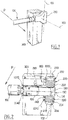
- the safety barrier according to the present invention comprises a rail 100 carried by a support crew 200 itself, preferably associated with a drive means placed in a trunk 300.
- the crew 200 is pivotally mounted about a horizontal main axis 202 on the trunk 300. Specifically, typically, the crew 200 is pivotally mounted back and forth about the axis 202 at a 90 ° angle. .
- the support crew 200 can thus be moved between a so-called horizontal position illustrated for example on the Figures 1, 2 , 4 and 5 and a so-called vertical position illustrated for example on the figure 3 inclined 90 ° from the anterior position.
- the boom 100 carried by the support crew 200 is horizontal. It extends transversely to the traffic lane and prohibits passage through it,
- the rail 100 is capable of displacement relative to the support assembly 200 about a secondary axis 102 transverse to the main axis 202.
- the rail is thus likely to be "disengaged" from the support crew 200.
- the secondary axis 102 In the rest position of the support crew 200, as illustrated in the Figures 1 and 2 the secondary axis 102 is vertical. On the contrary, in the vertical temporary position of the support crew 200, as illustrated in FIG. figure 3 the secondary axis 102 is horizontal.
- the rail 100 is maintained on the support assembly 200 by threshold means 110, 210 such that the rail 100 is not displaced with respect to the support crew 200 as long as a force greater than a threshold n ' is not applied to the smooth.
- these threshold means comprise a magnet 210 on the support assembly 200 and a pole plate 110 carried by the rail 100 (or conversely a polar plate carried by the support crew 200 and a magnet placed opposite on the rail 100).
- the safety barrier comprises elastic means 220 adapted to return the arm 100 in the rest position on the support crew 200, after unhinging.
- these elastic means are formed of one or more (two for example) springs 222, 224.
- the support assembly 200 comprises a stirrup 230 adapted to be fixed on the output shaft 310 of the drive means, which pivots around the main horizontal axis 202.
- the stirrup 230 is preferably made of metal, for example stainless steel.
- the stirrup 230 is formed of an elongate structure of U-shaped cross-section. It comprises a core 232 provided, on either side, with two lateral wings 234, 236 perpendicular to the core 232.
- the core 232 extends perpendicular to the main axis 202 of the output shaft 310 and is adapted to be fixed thereto.
- the arm 100 is rotatably mounted in the stirrup 230 around the secondary axis 102 transverse to the axis 202 of the output shaft 310 and perpendicular to the lateral wings 234, 236.
- the end of the arm 100 takes position, in the normal position of use, in the internal volume of the stirrup 230, between the two lateral wings 234, 236.
- an intermediate support 130 for example of thermoplastic material, is engaged on the end of the heald 100 and placed in the stirrup 230 to serve as an articulation piece between the heald 100 and the stirrup 230 around the axis 102, in the case of ejection of the arm 100.
- the intermediate support 130 preferably comprises two shells or flanges 131, 132 adapted to grip and clamp the end of the arm 100 by clamping when they are held by bolts 134 or any equivalent means.
- the elastic means 220 adapted to ensure the automatic rerouting of the heald 100 on the support unit 200 are preferably formed of two torsion springs 222, 224, coaxial with each other and coaxial with the secondary axis 102, mounted respectively from and other of the stirrup 230, on a respective cylindrical spacer 232, 234.
- each spacer 232, 234 has an enlarged head 233, 235, at its end, ensuring the maintenance of the respective spring 222, 224.
- the spacers 232, 234 are themselves centered on the secondary axis 102. They are preferably made of thermoplastic material.
- One end 2220, 2240 of each spring 222, 224, is connected to a tab 240 secured to the stirrup 230, more precisely to its web 232.
- the tab 240 extends generally parallel to the secondary axis 102.
- a second end 2222, 2242 of each spring 222, 224 is connected to the intermediate support 130, preferably respectively to one of the flanges 131, 132, and advantageously at a distance from the secondary axis 102 to apply a sufficient return torque on the intermediate crew 130 and the smooth 100 which is linked thereto.
- the springs 222, 224 are intended to ensure the automatic rerouting of the arm 100 on the support crew 200 in the case where the latter is ejected by pivoting about the secondary axis 102, by a vehicle .
- the rerouting of the bar 100 on the stirrup 230 is assured regardless of the position of the bar, horizontal or vertical, and its angle of disengagement, from 0 to 90 °.
- the springs 222, 224 are made of hardened Z10CN18.08 stainless steel and have a capacity of the order of 57Nm at 60 ° C.
- the intermediate support 130 carries a plate 110 forming a pole piece placed opposite a magnet 210 carried by the core 232 of the stirrup 230.
- These means 110, 210 ensure a maintenance of the arm 100 in position in the stirrup 200 as a force exceeding a threshold is not applied to the arm 100 to tend to pivot it around the secondary axis 102.
- the magnet 210 and / or the polar plate 110 are carried by their respective support with a certain degree of freedom of movement to ensure perfect contact between the facing faces of the polar plate 110 and the magnet 210, in the rest position of the safety barrier.
- This arrangement makes it possible to overcome any risk of lack of parallelism between the faces opposite these elements.
- the magnet 210 may be carried by the web 232 of the stirrup 230 via a damping rubber washer 212.
- a washer 212 makes it possible to provide flexibility of orientation to the magnet 210.
- the pole plate 110 comes off and allows the smooth to be ejected by pivoting about the secondary axis 102.
- the holding force of the magnet 210 may be of the order 160daN.
- the magnet 210 may be replaced by an electromagnet subject to ensuring the power supply thereof electrically.
- the safety barrier according to the present invention further comprises a protective cover 250 attached to the intermediate support 130, to follow the movements thereof.
- the hood 250 is intended to protect the system and ensure a certain aesthetics to the whole. It can be the subject of many embodiments and therefore will not be described in detail later.
- the safety barrier according to the present invention further comprises means adapted to detect the disengagement of the arm 100 with respect to the stirrup 230, that is to say the pivoting of the arm 100 relative to at the stirrup 230, around the secondary axis 102, outside its normal position of use. It is also preferably provided means adapted to automatically position the mobile assembly 200 in a vertical position, as illustrated on the figure 3 during such a detachment detection of the arm 100 so that the rerun of it on the support crew 200 under the effect of the bias exerted by the springs 222, 224, is operated outside the track of circulation.
- the aforementioned detection means can be the subject of many embodiments. They are preferably formed of an inductive sensor 260 carried by the core 232 of the stirrup 230 facing a complementary metal index 160 carried by the intermediate support 130.
- Such a sensor 260 detects the presence of the heald 100 in the normal position.
- the sensor 260 transmits the dismounting information of the arm 100, in the event of an impact, and in this case gives an order to open the barrier to position the mobile assembly 200 in a vertical position as illustrated on FIG. figure 3 . It also triggers a delay of the closing of the rail, to allow the spring 222, 224 to ensure the rerouting thereof in the open position, out of the way, before allowing the closing of the barrier.
- the operation of the safety barrier according to the present invention is essentially as follows.
- the hint presence sensor 260 gives the order to the management electronic card present in the terminal 300 and driving the drive means, d. carry out the mobile assembly 200 in a vertical position as illustrated in FIG. figure 3 . This rise can be timed or not.
- the two springs 222, 224 ensure the rerouting of the rail on the stirrup 230 in the initial operating position . Smooth 100 having returned to its position, the sensor 260 can instruct the system to resume its normal cycle.
- the safety barrier according to the present invention offers many advantages.
- the device according to the present invention allows automatic replacement of the barrier bar, in case of ejection thereof, which no longer requires human intervention. This prevents staff from going on the taxiway and greatly reduces the risk of accidents, especially at the toll gates.
- the system according to the present invention is adaptable to any type of barrier. It suffices to fix it on the rotation shaft 310 of the existing barriers.
- the heald 100 is made of composite material as defined in the patent application no. FR 03 14188 filed December 3, 2003 .
- Such a smooth is particularly light, in any case lighter than the traditionally used aluminum rails, so that it is not necessary to change the setting of the opening mechanism to account for the overweight caused by the rerouting mechanism proposed in the context of the present invention.
- Dismantling and rerouting take place at an angle of up to 90 °. Rooting is performed while the arm 100 is in the open position on the side of the track. It does not disturb the traffic.
- the means according to the present invention have a perfect symmetry with respect to their longitudinal axis. Thus a single model is sufficient for a smooth installation on the right or on the left.
- the intermediate support 130 and the stirrup 230 may be provided with means, typically bores 190, 290 adapted to receive a bolt or a pin or any equivalent means adapted to maintain the intermediate support 130 and therefore the smooth 100 on the mobile assembly 200 to prohibit, if the operator wishes, any disengagement of the arm 100 with respect to the stirrup 230.
- these means limiting the deflection of the arm are formed by the end of the intermediate support 130 capable of abutting against an edge 233 of the web 232 of the stirrup 230.
- the web 232 of the stirrup has a length less than that of the lateral wings 234, 236.
- the intermediate support 130 extends, at its end, beyond the secondary axis 102 on a length greater than its thickness considered transversely to this secondary axis 102.
- the height of the intermediate support 130 considered parallel to the secondary axis 102 is equal to the distance separating the two lateral wings 232, 234 to avoid any inadvertent play between the smooth 100 and the stirrup 230 in the normal position of use.
- the barrier comprises flexible support means of one of the holding means to allow self-positioning thereof.
- the barrier comprises means which prohibit positioning of the moving element in a horizontal position as long as the rail is not raised on the moving equipment.
Applications Claiming Priority (1)
| Application Number | Priority Date | Filing Date | Title |
|---|---|---|---|
| FR0502499A FR2883010B1 (fr) | 2005-03-14 | 2005-03-14 | Barriere de securite perfectionnee |
Publications (2)
| Publication Number | Publication Date |
|---|---|
| EP1703022A1 EP1703022A1 (fr) | 2006-09-20 |
| EP1703022B1 true EP1703022B1 (fr) | 2018-06-13 |
Family
ID=35045162
Family Applications (1)
| Application Number | Title | Priority Date | Filing Date |
|---|---|---|---|
| EP06111096.1A Active EP1703022B1 (fr) | 2005-03-14 | 2006-03-14 | Barrière de sécurité perfectionnée |
Country Status (6)
| Country | Link |
|---|---|
| US (1) | US20060228177A1 (es) |
| EP (1) | EP1703022B1 (es) |
| CN (1) | CN1837488B (es) |
| CA (1) | CA2539378A1 (es) |
| ES (1) | ES2686146T3 (es) |
| FR (1) | FR2883010B1 (es) |
Families Citing this family (24)
| Publication number | Priority date | Publication date | Assignee | Title |
|---|---|---|---|---|
| FR2863279B1 (fr) * | 2003-12-03 | 2006-01-20 | Bca Barrieres & Controle Dacces | Barriere levante de securite |
| US7481598B2 (en) * | 2006-08-01 | 2009-01-27 | The Chamberlain Group, Inc. | Extending barrier arm operator system and method |
| FR2906273A1 (fr) * | 2006-09-27 | 2008-03-28 | Deschamps Pere Et Fils Sa | Barriere escamotable de controle d'acces a une voie de circulation. |
| US7814706B2 (en) * | 2006-10-06 | 2010-10-19 | State of Florida, Department of Transportation | Dual-action breakaway gate safety system |
| US8161681B2 (en) * | 2008-06-30 | 2012-04-24 | Treihaft Michael T | Releasable arm assembly for a swing gate |
| CA2657744A1 (en) * | 2009-03-10 | 2010-09-10 | 9172-9863 Quebec Inc. | Magnetic barrier |
| JP5748450B2 (ja) * | 2010-06-11 | 2015-07-15 | 三菱重工業株式会社 | 車両通行遮断機 |
| RU2527120C2 (ru) * | 2010-07-12 | 2014-08-27 | Ла Баррьер Отоматик Сарл | Открывающееся заграждение, снабженное устройством автоматического закрывания |
| US20120011774A1 (en) * | 2010-07-15 | 2012-01-19 | Arnaud Roger R | Barrier Gate |
| JP5610994B2 (ja) * | 2010-11-09 | 2014-10-22 | 三菱重工業株式会社 | 車両通行遮断機 |
| FR2970719B1 (fr) * | 2011-01-21 | 2015-03-20 | Alain Antoniazzi | Portique securite |
| CN103161130A (zh) * | 2011-12-10 | 2013-06-19 | 江南大学 | 升降杆防撞击装置 |
| ITVR20120052A1 (it) | 2012-03-21 | 2013-09-22 | R I B S R L | Barriera per il controllo del transito di veicoli |
| US10208440B1 (en) | 2015-09-09 | 2019-02-19 | Safe Rack Llc | Traffic gate |
| CN105839562B (zh) * | 2016-03-28 | 2017-12-19 | 绍兴柯桥多泰纺织有限公司 | 防撞道闸 |
| CN105821784A (zh) * | 2016-03-28 | 2016-08-03 | 韦义乐 | 杆式道闸 |
| RU171166U1 (ru) * | 2016-12-30 | 2017-05-23 | Общество с ограниченной ответственностью "Фантом" (ООО "Фантом") | Автоматический шлагбаум |
| RU2667100C2 (ru) * | 2016-12-30 | 2018-09-14 | Общество с ограниченной ответственностью "Фантом" (ООО "Фантом") | Автоматический шлагбаум |
| RU174236U1 (ru) * | 2016-12-30 | 2017-10-09 | Евгений Викторович Филипенко | Автоматический шлагбаум |
| RU2667987C2 (ru) * | 2016-12-30 | 2018-09-25 | Общество с ограниченной ответственностью "Фантом" (ООО "Фантом") | Автоматический шлагбаум |
| US11047099B2 (en) * | 2018-09-14 | 2021-06-29 | Koei Industry Co., Ltd. | Pass blocking apparatus |
| WO2021146720A1 (en) * | 2020-01-17 | 2021-07-22 | Cubic Corporation | Auto-calibrating range sensing gate |
| EP4134769A4 (en) * | 2020-04-28 | 2023-06-21 | Huawei Technologies Co., Ltd. | METHOD AND DEVICE FOR A VEHICLE FOR PERFORMING A BOOM LOCK |
| CN113832895A (zh) * | 2021-11-04 | 2021-12-24 | 王志坚 | 一种保护车辆安全的道路桥梁弯道翻车自救装置 |
Family Cites Families (16)
| Publication number | Priority date | Publication date | Assignee | Title |
|---|---|---|---|---|
| US1356302A (en) * | 1920-10-19 | Anson c | ||
| US1535753A (en) * | 1923-04-16 | 1925-04-28 | Grant G Weiser | Automatic safety gate |
| US1628651A (en) * | 1926-01-26 | 1927-05-17 | John R Burress | Yinldable barrier for automatic railway-crossing gates |
| US4364200A (en) * | 1980-12-29 | 1982-12-21 | Kettering Medical Center | Automatically operable automotive vehicle gate apparatus provided with self protection and automotive protection |
| FR2585064A1 (fr) * | 1985-07-17 | 1987-01-23 | Bordeaux Parc Auto Sa Economie | Dispositif de barrage d'entree ou de sortie dans un parc automobile permettant d'eviter les deteriorations du materiel, par degondage a double sens (avant-arriere et axial) |
| US5653058A (en) * | 1995-11-17 | 1997-08-05 | Western-Cullen Hayes, Inc. | Railroad gate arm swivel adapter spring assembly |
| FR2764616B1 (fr) * | 1997-06-17 | 1999-08-27 | Pierre Deschamps | Barriere de securite, notamment barriere de passage a niveau ou de parking, comportant des moyens pour reperer ou signaler une deterioration de la lisse |
| US6460292B1 (en) * | 1999-07-09 | 2002-10-08 | Carlos A. Rodriguez | Barrier gate arm assembly and methods for use thereof |
| US6179517B1 (en) * | 1999-07-22 | 2001-01-30 | Kim L. Nelson | Traffic access control system |
| FR2800759B1 (fr) * | 1999-11-04 | 2001-12-21 | Jean Louis Claude Petit | Dispositif de degondage assiste, avec sa lisse, pour barriere |
| AUPQ794500A0 (en) * | 2000-06-02 | 2000-06-29 | Queensland Motorways Limited | Frangible barrier |
| US6470626B2 (en) * | 2001-01-17 | 2002-10-29 | Mtr, Inc. | Gate release mechanism with detent and plunger, and gate incorporating same |
| US7062879B2 (en) * | 2001-08-08 | 2006-06-20 | Federal Apd, Inc. | Security gate |
| ATE391208T1 (de) | 2002-08-09 | 2008-04-15 | Ero Ind | Aushebebarriere zur fahrzeugzugangsüberwachung |
| US6966146B2 (en) * | 2002-12-18 | 2005-11-22 | Western-Cullen-Hayes, Inc. | Two directional crossing gate arm protection assembly |
| FR2863279B1 (fr) * | 2003-12-03 | 2006-01-20 | Bca Barrieres & Controle Dacces | Barriere levante de securite |
-
2005
- 2005-03-14 FR FR0502499A patent/FR2883010B1/fr active Active
-
2006
- 2006-03-13 CA CA002539378A patent/CA2539378A1/fr not_active Abandoned
- 2006-03-14 CN CN2006100673223A patent/CN1837488B/zh not_active Expired - Fee Related
- 2006-03-14 ES ES06111096.1T patent/ES2686146T3/es active Active
- 2006-03-14 US US11/374,718 patent/US20060228177A1/en not_active Abandoned
- 2006-03-14 EP EP06111096.1A patent/EP1703022B1/fr active Active
Non-Patent Citations (1)
| Title |
|---|
| None * |
Also Published As
| Publication number | Publication date |
|---|---|
| FR2883010B1 (fr) | 2010-08-20 |
| EP1703022A1 (fr) | 2006-09-20 |
| ES2686146T3 (es) | 2018-10-16 |
| CN1837488B (zh) | 2011-11-16 |
| US20060228177A1 (en) | 2006-10-12 |
| CN1837488A (zh) | 2006-09-27 |
| FR2883010A1 (fr) | 2006-09-15 |
| CA2539378A1 (fr) | 2006-09-14 |
Similar Documents
| Publication | Publication Date | Title |
|---|---|---|
| EP1703022B1 (fr) | Barrière de sécurité perfectionnée | |
| EP0190976B1 (fr) | Mécanisme d'assistance à la fermeture d'une porte d'un véhicule automobile | |
| EP1108580A1 (fr) | Hayon de véhicule automobile | |
| FR2881998A1 (fr) | Porte coulissante stable | |
| EP0816568A2 (fr) | Barrière de sécurité pour voies de circulation de véhicules traversée d'un passage temporaire | |
| EP2003274B1 (fr) | Dispositif de mise en sécurite d'un acces de sécurité d'un accès des secours à une infrastructure publique | |
| FR2943693A1 (fr) | Barriere apte a se degonder et equipee d'un dispositif de regondage automatique. | |
| FR2886667A1 (fr) | Dispositif de fermeture et d'ouverture de vantail de porte ou portail | |
| EP1781526B1 (fr) | Structure pour vehicule automobile et vehicule equipe d'une telle structure | |
| EP2303620A1 (fr) | Dispositif de protection d'un ouvrant de vehicule | |
| EP0508923A1 (fr) | Dispositif de décrochage d'ancre | |
| EP1964974B1 (fr) | Dispositif de protection contre l'effraction | |
| FR3007385A1 (fr) | Borne escamotable constituant barriere ou moyen d amarrage ou mat support | |
| FR2882071A1 (fr) | Barriere escamotable de controle d'acces a une voie de circulation | |
| FR2906273A1 (fr) | Barriere escamotable de controle d'acces a une voie de circulation. | |
| FR2954367A1 (fr) | Bloc beton transferable | |
| FR2813243A1 (fr) | Porte coulissante de vehicule automobile demontable manuellement | |
| FR2862320A1 (fr) | Procede d'absorption de chocs contre une barriere de securite pour voies de circulation et barriere de securite de mise en oeuvre | |
| FR3020351A1 (fr) | Dispositif de chargement en dechets d'une benne de dechetterie depuis une plateforme | |
| FR2833222A1 (fr) | Dispositif de protection des pietons en cas de choc frontal avec un vehicule automobile | |
| FR2843410A1 (fr) | Barriere pour le controle d'acces de vehicules et comportant un dispositif de degondage | |
| FR3068062A1 (fr) | Dispositif de blocage | |
| FR3025238B1 (fr) | Ensemble arriere de vehicule pour l'ouverture et la fermeture d'un hayon | |
| FR2705118A1 (fr) | Portillon à bras tournants. | |
| FR2935732A1 (fr) | Dispositif de securite pour le capot avant d'une automobile, notamment pour le cas d'un choc pieton. |
Legal Events
| Date | Code | Title | Description |
|---|---|---|---|
| PUAI | Public reference made under article 153(3) epc to a published international application that has entered the european phase |
Free format text: ORIGINAL CODE: 0009012 |
|
| 17P | Request for examination filed |
Effective date: 20060314 |
|
| AK | Designated contracting states |
Kind code of ref document: A1 Designated state(s): AT BE BG CH CY CZ DE DK EE ES FI FR GB GR HU IE IS IT LI LT LU LV MC NL PL PT RO SE SI SK TR |
|
| AX | Request for extension of the european patent |
Extension state: AL BA HR MK YU |
|
| 17Q | First examination report despatched |
Effective date: 20070426 |
|
| AKX | Designation fees paid |
Designated state(s): AT BE BG CH CY CZ DE DK EE ES FI FR GB GR HU IE IS IT LI LT LU LV MC NL PL PT RO SE SI SK TR |
|
| AXX | Extension fees paid |
Extension state: YU Payment date: 20060314 Extension state: MK Payment date: 20060314 Extension state: HR Payment date: 20060314 |
|
| TPAC | Observations filed by third parties |
Free format text: ORIGINAL CODE: EPIDOSNTIPA |
|
| STAA | Information on the status of an ep patent application or granted ep patent |
Free format text: STATUS: EXAMINATION IS IN PROGRESS |
|
| GRAP | Despatch of communication of intention to grant a patent |
Free format text: ORIGINAL CODE: EPIDOSNIGR1 |
|
| STAA | Information on the status of an ep patent application or granted ep patent |
Free format text: STATUS: GRANT OF PATENT IS INTENDED |
|
| INTG | Intention to grant announced |
Effective date: 20170818 |
|
| GRAJ | Information related to disapproval of communication of intention to grant by the applicant or resumption of examination proceedings by the epo deleted |
Free format text: ORIGINAL CODE: EPIDOSDIGR1 |
|
| STAA | Information on the status of an ep patent application or granted ep patent |
Free format text: STATUS: EXAMINATION IS IN PROGRESS |
|
| INTC | Intention to grant announced (deleted) | ||
| GRAS | Grant fee paid |
Free format text: ORIGINAL CODE: EPIDOSNIGR3 |
|
| STAA | Information on the status of an ep patent application or granted ep patent |
Free format text: STATUS: GRANT OF PATENT IS INTENDED |
|
| GRAP | Despatch of communication of intention to grant a patent |
Free format text: ORIGINAL CODE: EPIDOSNIGR1 |
|
| INTG | Intention to grant announced |
Effective date: 20180202 |
|
| GRAA | (expected) grant |
Free format text: ORIGINAL CODE: 0009210 |
|
| STAA | Information on the status of an ep patent application or granted ep patent |
Free format text: STATUS: THE PATENT HAS BEEN GRANTED |
|
| AK | Designated contracting states |
Kind code of ref document: B1 Designated state(s): AT BE BG CH CY CZ DE DK EE ES FI FR GB GR HU IE IS IT LI LT LU LV MC NL PL PT RO SE SI SK TR |
|
| AX | Request for extension of the european patent |
Extension state: HR MK YU |
|
| REG | Reference to a national code |
Ref country code: GB Ref legal event code: FG4D Free format text: NOT ENGLISH |
|
| REG | Reference to a national code |
Ref country code: CH Ref legal event code: EP Ref country code: AT Ref legal event code: REF Ref document number: 1008658 Country of ref document: AT Kind code of ref document: T Effective date: 20180615 |
|
| REG | Reference to a national code |
Ref country code: DE Ref legal event code: R096 Ref document number: 602006055596 Country of ref document: DE |
|
| REG | Reference to a national code |
Ref country code: IE Ref legal event code: FG4D Free format text: LANGUAGE OF EP DOCUMENT: FRENCH |
|
| REG | Reference to a national code |
Ref country code: ES Ref legal event code: FG2A Ref document number: 2686146 Country of ref document: ES Kind code of ref document: T3 Effective date: 20181016 |
|
| RAP2 | Party data changed (patent owner data changed or rights of a patent transferred) |
Owner name: AUTOMATIC SYSTEMS |
|
| REG | Reference to a national code |
Ref country code: NL Ref legal event code: MP Effective date: 20180613 |
|
| REG | Reference to a national code |
Ref country code: LT Ref legal event code: MG4D |
|
| PG25 | Lapsed in a contracting state [announced via postgrant information from national office to epo] |
Ref country code: CY Free format text: LAPSE BECAUSE OF FAILURE TO SUBMIT A TRANSLATION OF THE DESCRIPTION OR TO PAY THE FEE WITHIN THE PRESCRIBED TIME-LIMIT Effective date: 20180613 Ref country code: FI Free format text: LAPSE BECAUSE OF FAILURE TO SUBMIT A TRANSLATION OF THE DESCRIPTION OR TO PAY THE FEE WITHIN THE PRESCRIBED TIME-LIMIT Effective date: 20180613 Ref country code: LT Free format text: LAPSE BECAUSE OF FAILURE TO SUBMIT A TRANSLATION OF THE DESCRIPTION OR TO PAY THE FEE WITHIN THE PRESCRIBED TIME-LIMIT Effective date: 20180613 Ref country code: BG Free format text: LAPSE BECAUSE OF FAILURE TO SUBMIT A TRANSLATION OF THE DESCRIPTION OR TO PAY THE FEE WITHIN THE PRESCRIBED TIME-LIMIT Effective date: 20180913 Ref country code: SE Free format text: LAPSE BECAUSE OF FAILURE TO SUBMIT A TRANSLATION OF THE DESCRIPTION OR TO PAY THE FEE WITHIN THE PRESCRIBED TIME-LIMIT Effective date: 20180613 |
|
| PG25 | Lapsed in a contracting state [announced via postgrant information from national office to epo] |
Ref country code: GR Free format text: LAPSE BECAUSE OF FAILURE TO SUBMIT A TRANSLATION OF THE DESCRIPTION OR TO PAY THE FEE WITHIN THE PRESCRIBED TIME-LIMIT Effective date: 20180914 Ref country code: LV Free format text: LAPSE BECAUSE OF FAILURE TO SUBMIT A TRANSLATION OF THE DESCRIPTION OR TO PAY THE FEE WITHIN THE PRESCRIBED TIME-LIMIT Effective date: 20180613 |
|
| REG | Reference to a national code |
Ref country code: AT Ref legal event code: MK05 Ref document number: 1008658 Country of ref document: AT Kind code of ref document: T Effective date: 20180613 |
|
| PG25 | Lapsed in a contracting state [announced via postgrant information from national office to epo] |
Ref country code: NL Free format text: LAPSE BECAUSE OF FAILURE TO SUBMIT A TRANSLATION OF THE DESCRIPTION OR TO PAY THE FEE WITHIN THE PRESCRIBED TIME-LIMIT Effective date: 20180613 |
|
| PG25 | Lapsed in a contracting state [announced via postgrant information from national office to epo] |
Ref country code: RO Free format text: LAPSE BECAUSE OF FAILURE TO SUBMIT A TRANSLATION OF THE DESCRIPTION OR TO PAY THE FEE WITHIN THE PRESCRIBED TIME-LIMIT Effective date: 20180613 Ref country code: CZ Free format text: LAPSE BECAUSE OF FAILURE TO SUBMIT A TRANSLATION OF THE DESCRIPTION OR TO PAY THE FEE WITHIN THE PRESCRIBED TIME-LIMIT Effective date: 20180613 Ref country code: SK Free format text: LAPSE BECAUSE OF FAILURE TO SUBMIT A TRANSLATION OF THE DESCRIPTION OR TO PAY THE FEE WITHIN THE PRESCRIBED TIME-LIMIT Effective date: 20180613 Ref country code: PL Free format text: LAPSE BECAUSE OF FAILURE TO SUBMIT A TRANSLATION OF THE DESCRIPTION OR TO PAY THE FEE WITHIN THE PRESCRIBED TIME-LIMIT Effective date: 20180613 Ref country code: AT Free format text: LAPSE BECAUSE OF FAILURE TO SUBMIT A TRANSLATION OF THE DESCRIPTION OR TO PAY THE FEE WITHIN THE PRESCRIBED TIME-LIMIT Effective date: 20180613 Ref country code: EE Free format text: LAPSE BECAUSE OF FAILURE TO SUBMIT A TRANSLATION OF THE DESCRIPTION OR TO PAY THE FEE WITHIN THE PRESCRIBED TIME-LIMIT Effective date: 20180613 Ref country code: IS Free format text: LAPSE BECAUSE OF FAILURE TO SUBMIT A TRANSLATION OF THE DESCRIPTION OR TO PAY THE FEE WITHIN THE PRESCRIBED TIME-LIMIT Effective date: 20181013 |
|
| REG | Reference to a national code |
Ref country code: DE Ref legal event code: R097 Ref document number: 602006055596 Country of ref document: DE |
|
| PLBE | No opposition filed within time limit |
Free format text: ORIGINAL CODE: 0009261 |
|
| STAA | Information on the status of an ep patent application or granted ep patent |
Free format text: STATUS: NO OPPOSITION FILED WITHIN TIME LIMIT |
|
| 26N | No opposition filed |
Effective date: 20190314 |
|
| PG25 | Lapsed in a contracting state [announced via postgrant information from national office to epo] |
Ref country code: DK Free format text: LAPSE BECAUSE OF FAILURE TO SUBMIT A TRANSLATION OF THE DESCRIPTION OR TO PAY THE FEE WITHIN THE PRESCRIBED TIME-LIMIT Effective date: 20180613 Ref country code: SI Free format text: LAPSE BECAUSE OF FAILURE TO SUBMIT A TRANSLATION OF THE DESCRIPTION OR TO PAY THE FEE WITHIN THE PRESCRIBED TIME-LIMIT Effective date: 20180613 |
|
| REG | Reference to a national code |
Ref country code: DE Ref legal event code: R119 Ref document number: 602006055596 Country of ref document: DE |
|
| PG25 | Lapsed in a contracting state [announced via postgrant information from national office to epo] |
Ref country code: MC Free format text: LAPSE BECAUSE OF FAILURE TO SUBMIT A TRANSLATION OF THE DESCRIPTION OR TO PAY THE FEE WITHIN THE PRESCRIBED TIME-LIMIT Effective date: 20180613 |
|
| REG | Reference to a national code |
Ref country code: CH Ref legal event code: PL |
|
| GBPC | Gb: european patent ceased through non-payment of renewal fee |
Effective date: 20190314 |
|
| PG25 | Lapsed in a contracting state [announced via postgrant information from national office to epo] |
Ref country code: LU Free format text: LAPSE BECAUSE OF NON-PAYMENT OF DUE FEES Effective date: 20190314 |
|
| REG | Reference to a national code |
Ref country code: BE Ref legal event code: MM Effective date: 20190331 |
|
| PG25 | Lapsed in a contracting state [announced via postgrant information from national office to epo] |
Ref country code: LI Free format text: LAPSE BECAUSE OF NON-PAYMENT OF DUE FEES Effective date: 20190331 Ref country code: GB Free format text: LAPSE BECAUSE OF NON-PAYMENT OF DUE FEES Effective date: 20190314 Ref country code: IE Free format text: LAPSE BECAUSE OF NON-PAYMENT OF DUE FEES Effective date: 20190314 Ref country code: CH Free format text: LAPSE BECAUSE OF NON-PAYMENT OF DUE FEES Effective date: 20190331 Ref country code: DE Free format text: LAPSE BECAUSE OF NON-PAYMENT OF DUE FEES Effective date: 20191001 |
|
| PG25 | Lapsed in a contracting state [announced via postgrant information from national office to epo] |
Ref country code: BE Free format text: LAPSE BECAUSE OF NON-PAYMENT OF DUE FEES Effective date: 20190331 |
|
| PG25 | Lapsed in a contracting state [announced via postgrant information from national office to epo] |
Ref country code: TR Free format text: LAPSE BECAUSE OF FAILURE TO SUBMIT A TRANSLATION OF THE DESCRIPTION OR TO PAY THE FEE WITHIN THE PRESCRIBED TIME-LIMIT Effective date: 20180613 |
|
| PG25 | Lapsed in a contracting state [announced via postgrant information from national office to epo] |
Ref country code: PT Free format text: LAPSE BECAUSE OF FAILURE TO SUBMIT A TRANSLATION OF THE DESCRIPTION OR TO PAY THE FEE WITHIN THE PRESCRIBED TIME-LIMIT Effective date: 20181015 |
|
| PG25 | Lapsed in a contracting state [announced via postgrant information from national office to epo] |
Ref country code: HU Free format text: LAPSE BECAUSE OF FAILURE TO SUBMIT A TRANSLATION OF THE DESCRIPTION OR TO PAY THE FEE WITHIN THE PRESCRIBED TIME-LIMIT; INVALID AB INITIO Effective date: 20060314 |
|
| PGFP | Annual fee paid to national office [announced via postgrant information from national office to epo] |
Ref country code: FR Payment date: 20230222 Year of fee payment: 18 |
|
| PGFP | Annual fee paid to national office [announced via postgrant information from national office to epo] |
Ref country code: IT Payment date: 20230221 Year of fee payment: 18 |
|
| PGFP | Annual fee paid to national office [announced via postgrant information from national office to epo] |
Ref country code: ES Payment date: 20230403 Year of fee payment: 18 |