EP1702664A2 - Installation de traitement de l'eau - Google Patents
Installation de traitement de l'eau Download PDFInfo
- Publication number
- EP1702664A2 EP1702664A2 EP20060010018 EP06010018A EP1702664A2 EP 1702664 A2 EP1702664 A2 EP 1702664A2 EP 20060010018 EP20060010018 EP 20060010018 EP 06010018 A EP06010018 A EP 06010018A EP 1702664 A2 EP1702664 A2 EP 1702664A2
- Authority
- EP
- European Patent Office
- Prior art keywords
- reactor
- filter
- water
- filter device
- filtrate
- Prior art date
- Legal status (The legal status is an assumption and is not a legal conclusion. Google has not performed a legal analysis and makes no representation as to the accuracy of the status listed.)
- Withdrawn
Links
Images


Classifications
-
- C—CHEMISTRY; METALLURGY
- C02—TREATMENT OF WATER, WASTE WATER, SEWAGE, OR SLUDGE
- C02F—TREATMENT OF WATER, WASTE WATER, SEWAGE, OR SLUDGE
- C02F1/00—Treatment of water, waste water, or sewage
- C02F1/44—Treatment of water, waste water, or sewage by dialysis, osmosis or reverse osmosis
- C02F1/444—Treatment of water, waste water, or sewage by dialysis, osmosis or reverse osmosis by ultrafiltration or microfiltration
-
- B—PERFORMING OPERATIONS; TRANSPORTING
- B01—PHYSICAL OR CHEMICAL PROCESSES OR APPARATUS IN GENERAL
- B01D—SEPARATION
- B01D33/00—Filters with filtering elements which move during the filtering operation
- B01D33/15—Filters with filtering elements which move during the filtering operation with rotary plane filtering surfaces
- B01D33/21—Filters with filtering elements which move during the filtering operation with rotary plane filtering surfaces with hollow filtering discs transversely mounted on a hollow rotary shaft
-
- B—PERFORMING OPERATIONS; TRANSPORTING
- B01—PHYSICAL OR CHEMICAL PROCESSES OR APPARATUS IN GENERAL
- B01D—SEPARATION
- B01D33/00—Filters with filtering elements which move during the filtering operation
- B01D33/58—Handling the filter cake in the filter for purposes other than for regenerating the filter cake remaining on the filtering element
- B01D33/68—Retarding cake deposition on the filter during the filtration period, e.g. using stirrers
-
- B—PERFORMING OPERATIONS; TRANSPORTING
- B01—PHYSICAL OR CHEMICAL PROCESSES OR APPARATUS IN GENERAL
- B01D—SEPARATION
- B01D33/00—Filters with filtering elements which move during the filtering operation
- B01D33/70—Filters with filtering elements which move during the filtering operation having feed or discharge devices
- B01D33/72—Filters with filtering elements which move during the filtering operation having feed or discharge devices for feeding
- B01D33/727—Filters with filtering elements which move during the filtering operation having feed or discharge devices for feeding provoking a tangential stream
-
- B—PERFORMING OPERATIONS; TRANSPORTING
- B01—PHYSICAL OR CHEMICAL PROCESSES OR APPARATUS IN GENERAL
- B01D—SEPARATION
- B01D61/00—Processes of separation using semi-permeable membranes, e.g. dialysis, osmosis or ultrafiltration; Apparatus, accessories or auxiliary operations specially adapted therefor
- B01D61/14—Ultrafiltration; Microfiltration
- B01D61/20—Accessories; Auxiliary operations
-
- B—PERFORMING OPERATIONS; TRANSPORTING
- B01—PHYSICAL OR CHEMICAL PROCESSES OR APPARATUS IN GENERAL
- B01D—SEPARATION
- B01D63/00—Apparatus in general for separation processes using semi-permeable membranes
- B01D63/16—Rotary, reciprocated or vibrated modules
-
- B—PERFORMING OPERATIONS; TRANSPORTING
- B01—PHYSICAL OR CHEMICAL PROCESSES OR APPARATUS IN GENERAL
- B01D—SEPARATION
- B01D65/00—Accessories or auxiliary operations, in general, for separation processes or apparatus using semi-permeable membranes
- B01D65/08—Prevention of membrane fouling or of concentration polarisation
-
- B—PERFORMING OPERATIONS; TRANSPORTING
- B01—PHYSICAL OR CHEMICAL PROCESSES OR APPARATUS IN GENERAL
- B01D—SEPARATION
- B01D2315/00—Details relating to the membrane module operation
- B01D2315/06—Submerged-type; Immersion type
-
- B—PERFORMING OPERATIONS; TRANSPORTING
- B01—PHYSICAL OR CHEMICAL PROCESSES OR APPARATUS IN GENERAL
- B01D—SEPARATION
- B01D2321/00—Details relating to membrane cleaning, regeneration, sterilization or to the prevention of fouling
- B01D2321/18—Use of gases
- B01D2321/185—Aeration
-
- B—PERFORMING OPERATIONS; TRANSPORTING
- B01—PHYSICAL OR CHEMICAL PROCESSES OR APPARATUS IN GENERAL
- B01D—SEPARATION
- B01D2321/00—Details relating to membrane cleaning, regeneration, sterilization or to the prevention of fouling
- B01D2321/20—By influencing the flow
- B01D2321/2008—By influencing the flow statically
- B01D2321/2025—Tangential inlet
-
- B—PERFORMING OPERATIONS; TRANSPORTING
- B01—PHYSICAL OR CHEMICAL PROCESSES OR APPARATUS IN GENERAL
- B01D—SEPARATION
- B01D2321/00—Details relating to membrane cleaning, regeneration, sterilization or to the prevention of fouling
- B01D2321/20—By influencing the flow
- B01D2321/2033—By influencing the flow dynamically
- B01D2321/2041—Mixers; Agitators
-
- C—CHEMISTRY; METALLURGY
- C02—TREATMENT OF WATER, WASTE WATER, SEWAGE, OR SLUDGE
- C02F—TREATMENT OF WATER, WASTE WATER, SEWAGE, OR SLUDGE
- C02F2301/00—General aspects of water treatment
- C02F2301/06—Pressure conditions
- C02F2301/066—Overpressure, high pressure
-
- C—CHEMISTRY; METALLURGY
- C02—TREATMENT OF WATER, WASTE WATER, SEWAGE, OR SLUDGE
- C02F—TREATMENT OF WATER, WASTE WATER, SEWAGE, OR SLUDGE
- C02F2303/00—Specific treatment goals
- C02F2303/18—Removal of treatment agents after treatment
-
- C—CHEMISTRY; METALLURGY
- C02—TREATMENT OF WATER, WASTE WATER, SEWAGE, OR SLUDGE
- C02F—TREATMENT OF WATER, WASTE WATER, SEWAGE, OR SLUDGE
- C02F3/00—Biological treatment of water, waste water, or sewage
- C02F3/02—Aerobic processes
- C02F3/06—Aerobic processes using submerged filters
-
- C—CHEMISTRY; METALLURGY
- C02—TREATMENT OF WATER, WASTE WATER, SEWAGE, OR SLUDGE
- C02F—TREATMENT OF WATER, WASTE WATER, SEWAGE, OR SLUDGE
- C02F3/00—Biological treatment of water, waste water, or sewage
- C02F3/02—Aerobic processes
- C02F3/12—Activated sludge processes
-
- C—CHEMISTRY; METALLURGY
- C02—TREATMENT OF WATER, WASTE WATER, SEWAGE, OR SLUDGE
- C02F—TREATMENT OF WATER, WASTE WATER, SEWAGE, OR SLUDGE
- C02F3/00—Biological treatment of water, waste water, or sewage
- C02F3/28—Anaerobic digestion processes
- C02F3/286—Anaerobic digestion processes including two or more steps
-
- Y—GENERAL TAGGING OF NEW TECHNOLOGICAL DEVELOPMENTS; GENERAL TAGGING OF CROSS-SECTIONAL TECHNOLOGIES SPANNING OVER SEVERAL SECTIONS OF THE IPC; TECHNICAL SUBJECTS COVERED BY FORMER USPC CROSS-REFERENCE ART COLLECTIONS [XRACs] AND DIGESTS
- Y02—TECHNOLOGIES OR APPLICATIONS FOR MITIGATION OR ADAPTATION AGAINST CLIMATE CHANGE
- Y02W—CLIMATE CHANGE MITIGATION TECHNOLOGIES RELATED TO WASTEWATER TREATMENT OR WASTE MANAGEMENT
- Y02W10/00—Technologies for wastewater treatment
- Y02W10/10—Biological treatment of water, waste water, or sewage
Definitions
- the present invention relates to a device for the treatment of water, in particular waste water and drinking water and a method for carrying out a treatment of water using this device.
- Water treatment involves the treatment of water with the aim of adapting its nature to the intended use as well as to specific requirements.
- Processes for treating drinking water include, for example, flocculation, filtration, aeration, de-ironing, demanganization, deacidification, disinfection, phosphating, denitrification and fluoridation processes.
- wastewater is modified water (dirty water) in its natural composition, as well as the less polluted rainwater and meltwater draining from built-up areas, the type and concentration of contaminants being highly dependent on the source of the wastewater are dependent.
- Wastewater treatment uses physical, chemical and / or biological processes, which often have to be used together to achieve a high degree of cleaning efficiency. In chemical processes, pollutants become more easily removable or into harmless reaction products transformed. For example, reactions that cause oxidation, reduction or the formation of sparingly soluble compounds are used.
- aerobic wastewater treatment In biological processes, the organic substances are metabolized by microorganisms and microorganisms with new formation of biomass to harmless compounds. Basically, a distinction is made between aerobic and anaerobic wastewater treatment.
- the aim of aerobic wastewater treatment is to reduce oxygen-depleting substances as far as possible, whereby organic substances are reduced by the organisms involved in the decomposition with formation of carbon dioxide, water, nitrates and sulfates.
- the basic requirement for aerobic systems is adequate ventilation with air (or oxygen-enriched air or pure oxygen).
- Anaerobic wastewater treatment ie the biological degradation of organic substances with the exclusion of oxygen, is also gaining in importance.
- Anaerobic digestion is fermentation processes (for example, alcohol, acetic acid, lactic acid, acetone-butanol fermentation, etc.).
- the wastewater contents are concentrated according to their physical properties such as particle size, density and rate of descent according to different methods.
- solid auxiliaries for example adsorption, filtration, ion exchange
- liquid auxiliaries extraction
- gaseous auxiliaries fractional auxiliaries
- thermal energy distillation, evaporation
- gravity settling, floating
- Membrane separation techniques and devices are used in many scientific and industrial applications except water treatment. Separation steps in membrane separation technology can be divided into the classes of micro-, ultra- and nanofiltration as well as reverse osmosis according to the separation limits. By means of these methods, particle sizes of up to 5 nm can be separated off. The solids are retained by the membrane and at least concentrate directly on the membrane while the filtered liquid passes through the membrane. A so-called concentration polarization causes a cover layer structure, which is also known as membrane fouling, which can be structurally influenced by different modes of operation. The classical modes of operation have become the dead-end and cross-flow filtration.
- the typical specific energy requirement for cross-flow ultrafiltration is, for example, 3 to 7 kWh / m 3 with filtrate flows of about 100 to 150 l / m 2 h and a transmembrane pressure of 3 to 5 bar.
- comparable values of about 0.1 to 0.5 kWh / m 3 result .
- the dead-end filtration results in even higher investment costs but lower operating costs.
- dipping systems are used, for example, in aeration tanks of sewage treatment plants, so that a certain reduction of the top layer formation by the movement of the liquid phase due to the fumigation takes place there is possible. Nevertheless, a significant reduction of the filtrate flow over time due to uncontrolled surface layer formation is a major obstacle to the economical use of such dipping systems in sewage treatment plants.
- a filtration module which consists of cassettes, which include disk-shaped flat membranes in which the feed can flow on all sides from the outside through the membranes.
- the permeate is discharged in the middle through a central manifold.
- this filter When operated as a cross-flow filter, this filter causes the problems described above, that is, the energy costs are very high. In particular at high overflow velocities and front feed of the feed solution, mechanical damage of the individual membrane disks may occur.
- the technical problem underlying the present invention is therefore to provide an economical method and a cost-effective device for water treatment, in particular for the filtration of high volume flows with little added value, in particular for cleaning municipal and industrial wastewater or drinking water obtained from surface waters.
- the present invention solves the underlying technical problem by providing a device for the treatment of water, in particular waste water or process water, comprising a reactor and a filter device in fluid communication with the reactor, wherein the filter device is arranged in the region of or below the reactor bottom and at least one with a hollow rotatable support body rotatably connected filter element, the interior of which is in fluid communication with the interior of the support body so that the filtrate from the interior of the at least one filter element into the interior of the support body and can be deducted from there.
- the inventively provided arrangement of the filter device in the region of or below the reactor bottom, inside or outside the reactor, allows the energetically advantageous exploitation of existing in many technical systems hydrostatic and / or hydrodynamic pressures to produce a transmembrane pressure gradient across the filter element.
- the filter device in particular in the lower region of the reactor, immerse in the liquid to be filtered or suspension and - preferably motor driven - to rotate about the longitudinal axis of the support body.
- the filter device that is to say the filter element arranged on the carrier body, in a preferably cylindrical housing and to position it below the reactor.
- filter device and reactor are to be connected to each other via inlet and outlet connections, for example pipes or hoses.
- the housing fills with the suspension to be filtered, wherein the support body is set in rotation about its longitudinal axis, for example by means of a motor.
- Filtrate is drawn in through the at least one filter disk arranged non-rotatably on the support body and withdrawn from the apparatus according to the invention through the hollow shaft which is in flow connection with the filter disk.
- the necessary for the filtration transmembrane pressure can, for example, by applying a negative pressure on the filtrate side of the filter device used in the invention Device done.
- the hydrostatic or hydrodynamic pressure present in many systems which are suitable for the present device is utilized as transmembrane pressure gradient.
- Modern wastewater treatment plants have, for example, aeration reactors of up to 20 m in height, whereby a transmembrane pressure gradient due to the hydrostatic pressure of almost 2 bar is possible.
- aerobically operating reactors frequently disperse the gas phase introduced for aeration by means of liquid jets, for example at speeds of up to 20 m / s.
- hydrodynamic pressures of, for example, up to 2 bar arise when the filter device used according to the invention is installed in the liquid circuit upstream of a nozzle, for example a two-fluid nozzle, for introducing liquid and / or gas or a gas mixture such as air.
- the invention enables the energetically advantageous decoupling of necessary for the filtration overflow velocity and other liquid movement, since necessary for the efficient filtration overflow velocity is generated by the rotation of the filter element.
- the necessary pressure gradient is generated as it were automatically and therefore cost by the, in particular at high height and level of the reactor, existing hydrostatic pressure.
- the device according to the invention therefore has several Advantages. Compared to cross-flow systems, significantly lower specific energy costs result and there is no danger of blockage for the filter elements. Compared with plate modules or Zee-Weed modules, which are installed in a wastewater reactor, there is the advantage that the oxygen supply aerobic microorganisms is decoupled from the filtration in the apparatus according to the invention, since the air supply and the liquid circulation for the gas dispersion largely independent of the desired filtration performance can be adjusted. The control of the top layer structure is achieved rather by the rotation of the disc filter and can thus be adjusted independently of the supply of aerobic microorganisms.
- the cover layer structure can be further influenced.
- the transmembrane pressure is generated by the hydrostatic pressure necessarily present in the wastewater reactors and, if necessary, additionally by the hydrodynamic pressure necessary for gas dispersion by means of a liquid jet.
- no appreciable additional pressure drop in the membrane module of the rotary disk filter is required because the flow through the module is not required to produce high overflow speeds, but only the hydrodynamic pressure is utilized and therefore the free flow cross section is sufficiently large can be selected so that virtually no additional pressure drop and thus energy requirements. This results significantly Lower specific energy costs than in cross-flow filtration.
- the interior of the support body via one or more openings, tubes, channels, lines, holes, slots, porous areas or the like with the interior of the support body in connection so that a liquid flow from the interior of the filter element can be made in the support body interior and thus a fluid connection is provided.
- the hollow support body is a hollow shaft, for example a tubular hollow shaft.
- it can be provided to carry out the filter element as a filter disk.
- the filter disk can be designed, for example, as a membrane-comprising or membrane-coated hollow body or hollow frame. According to the invention, it is possible to use, for example, technical membranes customarily used in membrane separation technology, for example polymer membranes, membrane filters, ultrafiltration membranes or microfiltration membranes.
- the invention thus also relates in a further embodiment to an aforementioned water treatment device with reactor and filter device, wherein the hollow support body is located in a housing, preferably rotatably mounted in a housing, in particular a cylindrical housing.
- a housing may, for example, have an inlet from the reactor and a drain, wherein liquid to be filtered through the inlet can be introduced into the housing and the separated solids can be removed by a drain.
- the inflow of the suspension to be filtered is advantageously tangential.
- the solids also referred to as concentrate, can be withdrawn via a tangential discharge on the cylinder wall or on the lower end wall. The filtrate leaves the housing through the hollow support body.
- the invention provides in a further preferred embodiment, that in the housing of the filter device internals for influencing the flow can be provided, for example, current breaker.
- the filter elements have passage openings for receiving the support body.
- the filter elements are arranged spaced apart in a preferred embodiment on the support body, wherein in a further preferred embodiment, the longitudinal axis of the support body perpendicular to the upper and lower sides, ie base surfaces, the filter element designed as a filter disk is.
- the invention thus provides that the at least one filter disc is rotatably mounted on a rotatable hollow shaft, that the filtrate can be deducted by this.
- the hollow shaft may be integrally formed and pass through the at least one filter disc through a, in a preferred embodiment centrally disposed in the latter passage opening, wherein at least one opening in the region of the hollow shaft is provided, which surrounds the filter disc with its inner circumferential surface, so that liquid from the filter disk can get into the interior of the hollow shaft.
- the support body in particular the hollow shaft is formed in several pieces from different, for example tubular, hollow sections, wherein the different sections of the support body are separated by liquid-tightly connected by filter elements arranged between them, in particular filter disks, and, as it were, to the liquid to be filtered to be filtered.
- a fluid connection for example, an opening between the interior of the support body and the filter element is provided. The penetrating into the interior of the filter discs filtrate can thus pass from the interior of the filter disc into the interior of the hollow shaft and be deducted from this.
- the invention further provides that the filter device used according to the invention is designed in a modular design.
- the filter device used according to the invention can be used in both aerobic and anaerobic systems, for example wastewater treatment or water treatment systems.
- the filter device can be installed, for example, in the activation stage of a sewage treatment plant and represents a modern system for biomass retention and thus for the concentration of biomass.
- the filter device can of course also be used in the separation of the feed to sewage treatment plants after or instead of the primary treatment.
- the feed is separated into a carbon-rich concentrate, which can be anaerobically converted to biogas, and a low-carbon filtrate, which can be aerobically reacted, for example, in high-performance wastewater reactors.
- the device according to the invention can thus be embodied as a device which has means for introducing air or gas and permits aerobic operating guides.
- the device according to the invention can also be embodied as an air-tight or gas-tight device or as a device equipped with an air-tight or gas-tight reactor or else it can be an anaerobic operation-permitting device by other measures.
- Such a device allows low-cost filtration in the course of bioprocesses that do not require atmospheric oxygen such as denitrification or even oxygen such as lactic acid, ethanol or acetone-butanol fermentation.
- the invention also solves the problem on which it is based by providing a process for the treatment of water, in particular wastewater and drinking water, in which a separation of a filtrate of solids from the water to be purified and wherein one of the devices according to the invention is used.
- the invention accordingly relates to a method for obtaining drinking water or for the purification of waste water, according to which a filter device to be used according to the invention, ie a hollow and rotatable, for example in a housing, mounted hollow body rotatable with at least one filter element, substantially only under influence hydrostatic and / or hydrodynamic pressure, exposed to the water to be purified and is placed in a rotational movement to generate an overflow velocity and withdrawn through the at least one filter element into the interior of the hollow support body inflowing filtrate through the hollow support body and thereby separated from the concentrate.
- a filter device to be used according to the invention ie a hollow and rotatable, for example in a housing, mounted hollow body rotatable with at least one filter element, substantially only under influence hydrostatic and / or hydrodynamic pressure, exposed to the water to be purified and is placed in a rotational movement to generate an overflow velocity and withdrawn through the at least one filter element into the interior of the hollow support body inflowing filtrate through the hollow support
- the reactor to be purified produces Liquid or suspension a hydrostatic pressure, which is arranged on a filter device according to the invention used in the lower region of the reactor, for example in the region of the reactor bottom or, if outside, in particular below the reactor, and then connected via connecting means to the reactor, acts such that transmembrane pressure gradient is generated via the filter element, which allows in an energetically favorable manner, the filtration of the liquid or suspension to be filtered.
- a nozzle in particular a two-fluid nozzle, is arranged in the reactor bottom, the air and fed from the filter device concentrate in the Injecting reactor and thereby generates an additional to the hydrostatic pressure acting pressure on the filter device, namely a hydrodynamic pressure.
- the invention relates in a further embodiment to an aforementioned method, wherein the water to be treated is feed water to a sewage treatment plant, which is supplied to an aforementioned apparatus for the treatment of water, in which the reactor is designed as the feed water containing feed basin and exiting according to the above method Filtrate after separation from the concentrate is fed to a feed tank downstream of the activation reactor, in a preferred embodiment part of another device according to the present invention. Accordingly, in such a process for the treatment of wastewater two devices according to the invention are connected in series, each having a reactor and a filter device.
- the liquid / suspension to be filtered out of the reactor via a pump into the filter device.
- the filtrate is withdrawn via the hollow shaft and the concentrate optionally together with air through a nozzle, in particular a two-fluid nozzle, re-introduced into the reactor, for example, in a wastewater reactor desired high cell densities of microorganisms can be achieved.
- the liquid / suspension to be filtered out of the reactor into the filter device preferably arranged in a housing, the filtrate being withdrawn from the hollow shaft and the concentrate being pumped to a nozzle preferably arranged in the reactor bottom , in particular a two-fluid nozzle, is passed, the the concentrate is introduced into the reactor together with air.
- the concentrate is not returned to the reactor again.
- the suspension to be filtered from the reactor can be supplied via a pump to the filter device, which is preferably arranged in a housing.
- the concentrate is discharged, for example in a digestion system and the filtrate is discharged through the hollow shaft.
- Some of the suspension / liquid brought in via the pump is not fed into the filter device, but rather directly to a nozzle, preferably arranged in the bottom of the reactor, which optionally together with air recycles the suspension back into the reactor. In this way, it is possible to set a specific cell density in the reactor in a controlled manner.
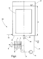
- FIG. 1 shows schematically a membrane module used according to the invention with rotating filter disks.
- FIGS 2 to 4 show various embodiments of the water treatment device according to the invention.
- FIG. 1 shows a filter device 1 embodied as a membrane module with a cylindrical housing 3 which has a liquid or suspension (C) containing a tangentially arranged inlet 5 for the solids to be filtered and a discharge opening 7 for the separated solids, ie the concentrate (FIG. A).
- a hollow shaft 9 is rotatably mounted, which carries a plurality of rotatably connected with her filter discs 11.
- the filtrate (B) is discharged from the hollow shaft 9.
- the tubular hollow shaft 9 is integrally formed and passes through the respective one, not shown, central passage openings having filter discs 11th
- the circulation of the circulating flow present in the reactor 40 is effected by a liquid-air jet irradiated at the reactor bottom 30.
- a liquid-air jet irradiated at the reactor bottom 30 For this purpose, is sucked from a pump 70, which is located outside of the reactor 40, 30 at the bottom of waste water and, via the lines 35 and 37 of a arranged in the reactor bottom 30 nozzle 60, in which the waste water is injected into the reactor 40 at high speed , whereby together with the sucked air 80 an intensive gas dispersion is achieved.
- a membrane module 1 is under the hydrostatic pressure of the liquid column of the wastewater reactor 40 and under the hydrodynamic pressure generated by the pump 70 by means of the nozzle 60.
- Both pressures produce a transmembrane pressure gradient, which allows the filtration of the wastewater in a cost effective manner.
- the filtrate stream B is discharged from the hollow shaft 9, while the concentrate stream A is directed to the nozzle 60 is injected into the reactor 40 together with air 80.
- FIG. 3 essentially shows the same wastewater reactor 40 as in FIG. 2.
- Identical reference symbols designate construction-identical or functionally identical parts.
- the filter device 1 is not arranged on the pressure side, but on the suction side of the pump 70, so that in this embodiment only the hydrostatic pressure acts as a transmembrane pressure gradient.
- the filter device 1 is arranged in a housing 3 below the reactor bottom 30 of the reactor 40.
- the device according to FIG. 4 essentially shows the same wastewater reactor 40 as in FIGS. 2 and 3.
- the filter device 1 is arranged on the pressure side of the pump 70.
- the concentrate stream A is not conducted to the nozzle 60, but is withdrawn from the membrane module 1 and can be passed directly to, for example, sludge digestion.
- the biomass concentration in the wastewater reactor 40 can be adjusted as desired.
- a modern wastewater treatment plant 100 is operated with a biological stage consisting of a loop reactor 40 with filtration unit 1 which is occupied by aerobic microorganisms.
- the wastewater has a chemical oxygen demand (COD) of about 7900 mg / l and accumulates at about 20,000 m 3 per year. It is biodegradable with a degree of degradation of 90% at a hydraulic residence time of about 20 h.
- the loop reactor 40 has a diameter of 2 m and a filling height H of 15 m, thus its liquid volume at a gas content of about 5% is about 45 m 3 .
- the loop reactor 40 at the bottom must be supplied with air having a volume flow of about 170 to 200 m 3 per hour.
- the supplied air stream is divided by means of a liquid jet generated by a nozzle 60 arranged in the bottom 30 of the reactor.
- the loop reactor 40 is withdrawn at the bottom 30, a liquid flow of about 35 m 3 / h and fed through lines 35 and 37 by means of a pump 70 of the nozzle 60 for gas dispersion.
- the resulting hydrodynamic pressure is about 2 bar, the static pressure due to the liquid column, however, is just under 1.5 bar.
- a gas dispersion can also be done without a nozzle, for example by means of static aerators, such as perforated plates, perforated tubes, plates, etc ..
- the required for the liquid jet Power input results without consideration of the pump efficiency to about 2 kW, resulting in a specific hydraulic power input of less than 50 W / m 3 results.
- the loop reactor 40 on the pressure side of the pump 70 is equipped with a filtration module 1 (FIG. 2). It is a rotary disc filter. This consists of 10 individual modules with about 1 m in length and each 100 ceramic filter discs 11 with about 0.15 m diameter and a mean pore diameter of about 0.1 microns.
- the modules are driven by means of an electric motor, not shown, with about 220 revolutions per minute, so that there is a specific filtrate flow of 70 1 / m 2 h, without significant cover layer formation occurs.
- the specific power requirement of this filtration is about 0.13 kWh / m 3 without consideration of the motor efficiency.
- the cover layer formation can be controlled acceptably and the result is a mean specific filtrate flow of about 70 l / m 2 h and thus comparable values for the device according to the invention in this point.
- To the required filtration area of To achieve about 32 m 2 about 240 such cross-flow filter tubes must be used, which are each incorporated into 10 individual tubes in a common module, of which then a total of 24 modules are needed.
- the specific power requirement of this cross-flow filtration is about 1.2 kWh per m 3 of filtrate and is thus almost ten times greater than in the inventive combination of wastewater reactor with rotary disk filter.
- the cross-flow filtration still has the disadvantage of the required very large volume flow (pump selection) and the tendency to clog, if particles are present in the wastewater to be cleaned, which have a larger diameter than the channel diameter (in this case, 6 mm) ,
Landscapes
- Chemical & Material Sciences (AREA)
- Chemical Kinetics & Catalysis (AREA)
- Engineering & Computer Science (AREA)
- Water Supply & Treatment (AREA)
- Life Sciences & Earth Sciences (AREA)
- Hydrology & Water Resources (AREA)
- Environmental & Geological Engineering (AREA)
- Organic Chemistry (AREA)
- Separation Using Semi-Permeable Membranes (AREA)
- Water Treatment By Sorption (AREA)
- Pretreatment Of Seeds And Plants (AREA)
- Treatment Of Water By Oxidation Or Reduction (AREA)
- Treatment Of Water By Ion Exchange (AREA)
- Agricultural Chemicals And Associated Chemicals (AREA)
- Fertilizers (AREA)
- Physical Water Treatments (AREA)
- Filtration Of Liquid (AREA)
Applications Claiming Priority (2)
| Application Number | Priority Date | Filing Date | Title |
|---|---|---|---|
| DE2000104096 DE10004096A1 (de) | 2000-01-31 | 2000-01-31 | Wasseraufbereitungsanlage |
| EP20010915172 EP1255698B1 (fr) | 2000-01-31 | 2001-01-27 | Installation de traitement des eaux |
Related Parent Applications (1)
| Application Number | Title | Priority Date | Filing Date |
|---|---|---|---|
| EP20010915172 Division EP1255698B1 (fr) | 2000-01-31 | 2001-01-27 | Installation de traitement des eaux |
Publications (2)
| Publication Number | Publication Date |
|---|---|
| EP1702664A2 true EP1702664A2 (fr) | 2006-09-20 |
| EP1702664A3 EP1702664A3 (fr) | 2007-09-05 |
Family
ID=7629292
Family Applications (2)
| Application Number | Title | Priority Date | Filing Date |
|---|---|---|---|
| EP20060010018 Withdrawn EP1702664A3 (fr) | 2000-01-31 | 2001-01-27 | Installation de traitement de l'eau |
| EP20010915172 Expired - Lifetime EP1255698B1 (fr) | 2000-01-31 | 2001-01-27 | Installation de traitement des eaux |
Family Applications After (1)
| Application Number | Title | Priority Date | Filing Date |
|---|---|---|---|
| EP20010915172 Expired - Lifetime EP1255698B1 (fr) | 2000-01-31 | 2001-01-27 | Installation de traitement des eaux |
Country Status (11)
| Country | Link |
|---|---|
| US (1) | US7037429B2 (fr) |
| EP (2) | EP1702664A3 (fr) |
| CN (1) | CN1396890A (fr) |
| AT (1) | ATE356783T1 (fr) |
| BR (1) | BR0108021B1 (fr) |
| CY (1) | CY1106489T1 (fr) |
| DE (2) | DE10004096A1 (fr) |
| DK (1) | DK1255698T3 (fr) |
| ES (1) | ES2282239T3 (fr) |
| PT (1) | PT1255698E (fr) |
| WO (1) | WO2001056937A1 (fr) |
Cited By (3)
| Publication number | Priority date | Publication date | Assignee | Title |
|---|---|---|---|---|
| WO2011050825A1 (fr) * | 2009-11-02 | 2011-05-05 | Kmpt Ag | Dispositif pour séparer des fluides |
| RU2478204C2 (ru) * | 2007-07-09 | 2013-03-27 | Мбонлайн Гмбх | Устройство для контроля воды на бактерии |
| DE102011083954A1 (de) | 2011-10-04 | 2013-04-04 | bioprocess consulting | Schwingungsbasierte Querstromfiltrationsvorrichtung |
Families Citing this family (12)
| Publication number | Priority date | Publication date | Assignee | Title |
|---|---|---|---|---|
| DE10140709B4 (de) * | 2001-08-24 | 2006-02-02 | Z-Filter Gmbh + Co. Kg | Verfahren zum Pflegen und Reinigen eines Arbeitsmediums |
| DE10154549B4 (de) | 2001-11-07 | 2005-12-29 | Fraunhofer-Gesellschaft zur Förderung der angewandten Forschung e.V. | Vorrichtung zum Trennen von Stoffen |
| DE102005018946A1 (de) * | 2005-04-22 | 2006-10-26 | Stengelin Gmbh & Co. Kg Anlagenbau Und Verfahrenstechnik | Vorrichtung und Verfahren zur Membran-Filtration |
| DE102005034138A1 (de) * | 2005-07-19 | 2007-01-25 | Fraunhofer-Gesellschaft zur Förderung der angewandten Forschung e.V. | Reaktor zur Gewinnung von Magnesiumammoniumphosphat und Verfahren zur Gewinnung von Magnesiumammoniumphosphat aus Gülle oder ammoniumhaltigen Abgasen |
| EP1854764B1 (fr) * | 2006-05-10 | 2016-12-14 | Grundfos Management A/S | Réacteur d'empilement de plaques filtrantes |
| DE102009043134B4 (de) * | 2009-09-18 | 2014-05-22 | Bgd Boden- Und Grundwasserlabor Gmbh | Verfahren zur Ermittlung von Stoffaustauschraten zwischen Wasserkörper und porösen Medien in Oberflächengewässern |
| DE102009051588A1 (de) | 2009-10-20 | 2011-04-21 | Fraunhofer-Gesellschaft zur Förderung der angewandten Forschung e.V. | Algenkulturverfahren |
| US9926212B2 (en) | 2014-12-22 | 2018-03-27 | PRO-Equipment, Inc. | High velocity cross flow dynamic membrane filter |
| DE102016109802A1 (de) * | 2016-05-27 | 2017-11-30 | Gottfried Wilhelm Leibniz Universität Hannover | Anordnung zur Behandlung von Wässern mit mindestens zwei Tauchkörpern und Verfahren zur Behandlung von Wässern hiermit |
| CN107673516A (zh) * | 2017-11-16 | 2018-02-09 | 南宁众创空间科技有限公司 | 一种多层次生活污水初级处理装置 |
| GB2586592A (en) * | 2019-08-21 | 2021-03-03 | Xeros Ltd | New filter, filter unit, treatment apparatus, method and use |
| EP4137554B1 (fr) * | 2021-08-18 | 2024-10-02 | ANDRITZ Separation GmbH | Agencement de fermenteur |
Citations (3)
| Publication number | Priority date | Publication date | Assignee | Title |
|---|---|---|---|---|
| US4079008A (en) * | 1976-07-07 | 1978-03-14 | Worthington Pump, Inc. | Mixing apparatus for biochemical treatment of fluids with oxygen |
| JPH0576899A (ja) * | 1991-09-20 | 1993-03-30 | Hitachi Kiden Kogyo Ltd | 汚泥の好気性消化方法 |
| DE19648519A1 (de) * | 1996-11-23 | 1998-06-04 | Preussag Noell Wassertech | Verfahren und Anlage zur Stofftrennung mittels Membranfiltration |
Family Cites Families (9)
| Publication number | Priority date | Publication date | Assignee | Title |
|---|---|---|---|---|
| JPS61274799A (ja) * | 1985-05-31 | 1986-12-04 | Agency Of Ind Science & Technol | 廃水の処理装置 |
| JPS62273100A (ja) * | 1986-05-22 | 1987-11-27 | Kubota Ltd | 下水処理方法 |
| JPH0698275B2 (ja) | 1986-05-28 | 1994-12-07 | 日立プラント建設株式会社 | 液体の濃縮装置 |
| KR19990064179A (ko) * | 1995-10-10 | 1999-07-26 | 와이너 길버트 피. | 동적 스월필터 조립체 및 이를 이용한 여과 방법 |
| DE19624176C2 (de) * | 1996-06-18 | 1998-05-07 | Franz Koppe | Filterplatte |
| JPH10128393A (ja) * | 1996-10-31 | 1998-05-19 | Mitsubishi Rayon Co Ltd | 廃水処理方法および廃水処理装置 |
| DE19647512A1 (de) * | 1996-11-16 | 1998-05-20 | Damann Franz Josef | Mobile Klärvorrichtung |
| DE19717448A1 (de) * | 1997-04-25 | 1997-10-02 | Peter Dr Lueth | Vorrichtung und Filtrationsverfahren zur Abtrennung von Stoffen aus Suspensionen |
| FR2799391B1 (fr) | 1999-10-07 | 2001-11-30 | Degremont | Perfectionnements apportes aux equipements de separation solide/liquide notamment pour l'epuration biologique |
-
2000
- 2000-01-31 DE DE2000104096 patent/DE10004096A1/de not_active Withdrawn
-
2001
- 2001-01-27 CN CN01804298A patent/CN1396890A/zh active Pending
- 2001-01-27 EP EP20060010018 patent/EP1702664A3/fr not_active Withdrawn
- 2001-01-27 EP EP20010915172 patent/EP1255698B1/fr not_active Expired - Lifetime
- 2001-01-27 ES ES01915172T patent/ES2282239T3/es not_active Expired - Lifetime
- 2001-01-27 WO PCT/EP2001/000903 patent/WO2001056937A1/fr active IP Right Grant
- 2001-01-27 US US10/182,790 patent/US7037429B2/en not_active Expired - Lifetime
- 2001-01-27 DK DK01915172T patent/DK1255698T3/da active
- 2001-01-27 DE DE50112191T patent/DE50112191D1/de not_active Expired - Lifetime
- 2001-01-27 AT AT01915172T patent/ATE356783T1/de active
- 2001-01-27 PT PT01915172T patent/PT1255698E/pt unknown
- 2001-01-27 BR BR0108021A patent/BR0108021B1/pt not_active IP Right Cessation
-
2007
- 2007-04-04 CY CY20071100479T patent/CY1106489T1/el unknown
Patent Citations (3)
| Publication number | Priority date | Publication date | Assignee | Title |
|---|---|---|---|---|
| US4079008A (en) * | 1976-07-07 | 1978-03-14 | Worthington Pump, Inc. | Mixing apparatus for biochemical treatment of fluids with oxygen |
| JPH0576899A (ja) * | 1991-09-20 | 1993-03-30 | Hitachi Kiden Kogyo Ltd | 汚泥の好気性消化方法 |
| DE19648519A1 (de) * | 1996-11-23 | 1998-06-04 | Preussag Noell Wassertech | Verfahren und Anlage zur Stofftrennung mittels Membranfiltration |
Non-Patent Citations (2)
| Title |
|---|
| PATENT ABSTRACTS OF JAPAN Bd. 012, Nr. 159 (C-495), 14. Mai 1988 (1988-05-14) -& JP 62 273100 A (KUBOTA LTD), 27. November 1987 (1987-11-27) * |
| PATENT ABSTRACTS OF JAPAN Bd. 012, Nr. 172 (C-497), 21. Mai 1988 (1988-05-21) -& JP 62 279807 A (HITACHI PLANT ENG & CONSTR CO LTD), 4. Dezember 1987 (1987-12-04) * |
Cited By (3)
| Publication number | Priority date | Publication date | Assignee | Title |
|---|---|---|---|---|
| RU2478204C2 (ru) * | 2007-07-09 | 2013-03-27 | Мбонлайн Гмбх | Устройство для контроля воды на бактерии |
| WO2011050825A1 (fr) * | 2009-11-02 | 2011-05-05 | Kmpt Ag | Dispositif pour séparer des fluides |
| DE102011083954A1 (de) | 2011-10-04 | 2013-04-04 | bioprocess consulting | Schwingungsbasierte Querstromfiltrationsvorrichtung |
Also Published As
| Publication number | Publication date |
|---|---|
| DE50112191D1 (de) | 2007-04-26 |
| EP1255698B1 (fr) | 2007-03-14 |
| US7037429B2 (en) | 2006-05-02 |
| DK1255698T3 (da) | 2007-07-16 |
| EP1702664A3 (fr) | 2007-09-05 |
| DE10004096A1 (de) | 2001-08-09 |
| BR0108021A (pt) | 2002-10-29 |
| WO2001056937A1 (fr) | 2001-08-09 |
| EP1255698A1 (fr) | 2002-11-13 |
| CN1396890A (zh) | 2003-02-12 |
| CY1106489T1 (el) | 2012-01-25 |
| BR0108021B1 (pt) | 2010-09-08 |
| US20030150822A1 (en) | 2003-08-14 |
| ES2282239T3 (es) | 2007-10-16 |
| ATE356783T1 (de) | 2007-04-15 |
| PT1255698E (pt) | 2007-06-21 |
Similar Documents
| Publication | Publication Date | Title |
|---|---|---|
| EP1255698B1 (fr) | Installation de traitement des eaux | |
| DE2815866C2 (fr) | ||
| EP0503649B1 (fr) | Procédé et dispositif pour la purification biologique d'eaux usées polluées par des substances non ou difficilement dégradables | |
| DE69627397T2 (de) | System zur Permeatentnahme aus einem flüssigen Substrat mit mehreren Bestandteilen | |
| US7713413B2 (en) | Aerated anoxic membrane bioreactor | |
| US7481933B2 (en) | Process to improve the efficiency of a membrane filter activated sludge system | |
| EP2465824B1 (fr) | Configurations de bioréacteur de membrane (mbr) pour le traitement des eaux usées | |
| DE69527021T2 (de) | Vorrichtung und Verfahren zum Entsalzen von Meerwasser durch mehrstufige Umkehrosmose | |
| EP1503848B1 (fr) | Dispositif de filtration a membranes sous forme de fibres creuses et son utilisation pour la purification d'eaux usees, ainsi que bioreacteur a membranes | |
| DE102004019669A1 (de) | Verfahren und System zur Behandlung von Abwasser, das organische Bestandteile enthält | |
| DE60304456T2 (de) | Membran-hybridbioreaktor zur behandlung von städtischem und industriellem abwasser | |
| Daels et al. | The use of electrospun flat sheet nanofibre membranes in MBR applications | |
| EP0891302B1 (fr) | Procede d'epuration biologique d'eaux usees | |
| DE102010043662B4 (de) | Brauereiabwasseraufbereitungsverfahren sowie Brauereiabwasseraufbereitungsvorrichtung | |
| KR102100991B1 (ko) | 다공성 세라믹 분리막을 이용한 액비정제장치 | |
| DE602004009084T2 (de) | Prozess zur Reinigung eines Tauchmembranmoduls, Gasleitungssystem zur Reinigung einer solchen Membran und Filtrationstank mit Gasleitungssystem | |
| DE19753326A1 (de) | Verfahren und Vorrichtung zur biologischen Reinigung von Abwässern | |
| EP1265819B1 (fr) | Procede et dispositif pour l'epuration d'eaux usees | |
| JP2007190488A (ja) | 膜分離活性汚泥処理装置 | |
| DE19749411C1 (de) | Verfahren und Vorrichtung zur biologischen Wasserreinigung | |
| EP0812807A2 (fr) | Procédé et réacteur pour le traitement microbiologique continue des eaux usées fortement polluées | |
| DE9304698U1 (de) | Anlage zur Reinigung von Flüssigkeiten | |
| KR20200101663A (ko) | 축산폐수의 여과와 여과막의 세정이 가능한 장치 | |
| DE19734759C1 (de) | Verfahren und Vorrichtung zur biologischen Abwasserreinigung | |
| CH456477A (de) | Verfahren zur Konzentration biologischer Feststoffe in einem Reaktionssystem sowie biologisches Reaktionssystem zur Ausführung des Verfahrens |
Legal Events
| Date | Code | Title | Description |
|---|---|---|---|
| PUAI | Public reference made under article 153(3) epc to a published international application that has entered the european phase |
Free format text: ORIGINAL CODE: 0009012 |
|
| AC | Divisional application: reference to earlier application |
Ref document number: 1255698 Country of ref document: EP Kind code of ref document: P |
|
| AK | Designated contracting states |
Kind code of ref document: A2 Designated state(s): AT BE CH CY DE DK ES FI FR GB GR IE IT LI LU MC NL PT SE TR |
|
| RIN1 | Information on inventor provided before grant (corrected) |
Inventor name: STERNAD, WERNER, DR. Inventor name: TROESCH , WALTER, PROF. DR. Inventor name: SCHLIESSMANN, URSULA, DIPL.-ING. Inventor name: STROH, NORBERT , DIPL.-ING. |
|
| PUAL | Search report despatched |
Free format text: ORIGINAL CODE: 0009013 |
|
| AK | Designated contracting states |
Kind code of ref document: A3 Designated state(s): AT BE CH CY DE DK ES FI FR GB GR IE IT LI LU MC NL PT SE TR |
|
| RIC1 | Information provided on ipc code assigned before grant |
Ipc: C02F 3/12 20060101ALN20060803BHEP Ipc: C02F 1/44 20060101ALI20070727BHEP Ipc: B01D 1/02 20060101ALI20070727BHEP Ipc: C02F 1/00 20060101ALI20070727BHEP Ipc: B01D 33/21 20060101AFI20060803BHEP Ipc: C02F 3/06 20060101ALN20060803BHEP Ipc: C02F 3/28 20060101ALN20060803BHEP Ipc: B01D 65/08 20060101ALI20070727BHEP Ipc: B01D 21/00 20060101ALI20070727BHEP Ipc: B01D 63/16 20060101ALI20070727BHEP Ipc: B01D 61/20 20060101ALI20070727BHEP |
|
| 17P | Request for examination filed |
Effective date: 20080305 |
|
| 17Q | First examination report despatched |
Effective date: 20080403 |
|
| AKX | Designation fees paid |
Designated state(s): AT BE CH CY DE DK ES FI FR GB GR IE IT LI LU MC NL PT SE TR |
|
| STAA | Information on the status of an ep patent application or granted ep patent |
Free format text: STATUS: THE APPLICATION IS DEEMED TO BE WITHDRAWN |
|
| 18D | Application deemed to be withdrawn |
Effective date: 20080814 |