EP1701802B1 - Hochfrequenzzerstäubungsvorrichtung - Google Patents
Hochfrequenzzerstäubungsvorrichtung Download PDFInfo
- Publication number
- EP1701802B1 EP1701802B1 EP05700704A EP05700704A EP1701802B1 EP 1701802 B1 EP1701802 B1 EP 1701802B1 EP 05700704 A EP05700704 A EP 05700704A EP 05700704 A EP05700704 A EP 05700704A EP 1701802 B1 EP1701802 B1 EP 1701802B1
- Authority
- EP
- European Patent Office
- Prior art keywords
- coating
- substrate
- spray
- atomising
- housing
- Prior art date
- Legal status (The legal status is an assumption and is not a legal conclusion. Google has not performed a legal analysis and makes no representation as to the accuracy of the status listed.)
- Expired - Lifetime
Links
- 238000005507 spraying Methods 0.000 title description 4
- 238000000576 coating method Methods 0.000 claims abstract description 174
- 239000011248 coating agent Substances 0.000 claims abstract description 159
- 239000000758 substrate Substances 0.000 claims abstract description 128
- 239000007921 spray Substances 0.000 claims abstract description 94
- 239000003595 mist Substances 0.000 claims abstract description 14
- 239000012530 fluid Substances 0.000 claims abstract description 7
- 239000011261 inert gas Substances 0.000 claims description 49
- 238000001035 drying Methods 0.000 claims description 35
- 230000005684 electric field Effects 0.000 claims description 13
- 238000000034 method Methods 0.000 claims description 13
- 238000010438 heat treatment Methods 0.000 claims description 12
- 230000008569 process Effects 0.000 claims description 10
- 238000003860 storage Methods 0.000 claims description 9
- 239000007789 gas Substances 0.000 claims description 8
- 230000003750 conditioning effect Effects 0.000 claims description 6
- 230000002349 favourable effect Effects 0.000 claims description 2
- 230000008021 deposition Effects 0.000 abstract description 2
- 239000007788 liquid Substances 0.000 description 89
- 238000004544 sputter deposition Methods 0.000 description 45
- 239000002245 particle Substances 0.000 description 27
- 238000000889 atomisation Methods 0.000 description 18
- 238000009826 distribution Methods 0.000 description 13
- 239000002904 solvent Substances 0.000 description 12
- 239000010408 film Substances 0.000 description 11
- 239000000463 material Substances 0.000 description 10
- 229910052751 metal Inorganic materials 0.000 description 10
- 239000002184 metal Substances 0.000 description 10
- 239000000243 solution Substances 0.000 description 9
- 239000013543 active substance Substances 0.000 description 8
- 238000001723 curing Methods 0.000 description 8
- 230000007704 transition Effects 0.000 description 8
- 239000006185 dispersion Substances 0.000 description 7
- 230000001976 improved effect Effects 0.000 description 7
- 239000000203 mixture Substances 0.000 description 7
- 230000009471 action Effects 0.000 description 6
- 230000008859 change Effects 0.000 description 6
- 230000005855 radiation Effects 0.000 description 6
- 239000000126 substance Substances 0.000 description 6
- 238000001816 cooling Methods 0.000 description 5
- 239000000839 emulsion Substances 0.000 description 5
- 238000005516 engineering process Methods 0.000 description 5
- 239000000725 suspension Substances 0.000 description 5
- -1 metal oxides iron oxide Chemical class 0.000 description 4
- 230000010355 oscillation Effects 0.000 description 4
- UHOVQNZJYSORNB-UHFFFAOYSA-N Benzene Chemical compound C1=CC=CC=C1 UHOVQNZJYSORNB-UHFFFAOYSA-N 0.000 description 3
- LFQSCWFLJHTTHZ-UHFFFAOYSA-N Ethanol Chemical compound CCO LFQSCWFLJHTTHZ-UHFFFAOYSA-N 0.000 description 3
- OKKJLVBELUTLKV-UHFFFAOYSA-N Methanol Chemical compound OC OKKJLVBELUTLKV-UHFFFAOYSA-N 0.000 description 3
- LRHPLDYGYMQRHN-UHFFFAOYSA-N N-Butanol Chemical compound CCCCO LRHPLDYGYMQRHN-UHFFFAOYSA-N 0.000 description 3
- DNIAPMSPPWPWGF-UHFFFAOYSA-N Propylene glycol Chemical compound CC(O)CO DNIAPMSPPWPWGF-UHFFFAOYSA-N 0.000 description 3
- YXFVVABEGXRONW-UHFFFAOYSA-N Toluene Chemical compound CC1=CC=CC=C1 YXFVVABEGXRONW-UHFFFAOYSA-N 0.000 description 3
- 210000004351 coronary vessel Anatomy 0.000 description 3
- 238000004132 cross linking Methods 0.000 description 3
- MTHSVFCYNBDYFN-UHFFFAOYSA-N diethylene glycol Chemical compound OCCOCCO MTHSVFCYNBDYFN-UHFFFAOYSA-N 0.000 description 3
- 239000003814 drug Substances 0.000 description 3
- 239000007943 implant Substances 0.000 description 3
- 238000002844 melting Methods 0.000 description 3
- 230000008018 melting Effects 0.000 description 3
- 239000007787 solid Substances 0.000 description 3
- 229910000859 α-Fe Inorganic materials 0.000 description 3
- SVTBMSDMJJWYQN-UHFFFAOYSA-N 2-methylpentane-2,4-diol Chemical compound CC(O)CC(C)(C)O SVTBMSDMJJWYQN-UHFFFAOYSA-N 0.000 description 2
- LCGLNKUTAGEVQW-UHFFFAOYSA-N Dimethyl ether Chemical compound COC LCGLNKUTAGEVQW-UHFFFAOYSA-N 0.000 description 2
- LYCAIKOWRPUZTN-UHFFFAOYSA-N Ethylene glycol Chemical compound OCCO LYCAIKOWRPUZTN-UHFFFAOYSA-N 0.000 description 2
- KFZMGEQAYNKOFK-UHFFFAOYSA-N Isopropanol Chemical compound CC(C)O KFZMGEQAYNKOFK-UHFFFAOYSA-N 0.000 description 2
- PXHVJJICTQNCMI-UHFFFAOYSA-N Nickel Chemical compound [Ni] PXHVJJICTQNCMI-UHFFFAOYSA-N 0.000 description 2
- ISWSIDIOOBJBQZ-UHFFFAOYSA-N Phenol Chemical compound OC1=CC=CC=C1 ISWSIDIOOBJBQZ-UHFFFAOYSA-N 0.000 description 2
- WYURNTSHIVDZCO-UHFFFAOYSA-N Tetrahydrofuran Chemical compound C1CCOC1 WYURNTSHIVDZCO-UHFFFAOYSA-N 0.000 description 2
- 239000004480 active ingredient Substances 0.000 description 2
- 239000000654 additive Substances 0.000 description 2
- 230000002411 adverse Effects 0.000 description 2
- 230000008901 benefit Effects 0.000 description 2
- 238000007872 degassing Methods 0.000 description 2
- 230000006866 deterioration Effects 0.000 description 2
- 229940079593 drug Drugs 0.000 description 2
- 230000000694 effects Effects 0.000 description 2
- 230000005484 gravity Effects 0.000 description 2
- ZSIAUFGUXNUGDI-UHFFFAOYSA-N hexan-1-ol Chemical compound CCCCCCO ZSIAUFGUXNUGDI-UHFFFAOYSA-N 0.000 description 2
- 230000006698 induction Effects 0.000 description 2
- 230000001939 inductive effect Effects 0.000 description 2
- 230000001788 irregular Effects 0.000 description 2
- 229910044991 metal oxide Inorganic materials 0.000 description 2
- 239000002105 nanoparticle Substances 0.000 description 2
- 239000006199 nebulizer Substances 0.000 description 2
- 239000002243 precursor Substances 0.000 description 2
- BDERNNFJNOPAEC-UHFFFAOYSA-N propan-1-ol Chemical compound CCCO BDERNNFJNOPAEC-UHFFFAOYSA-N 0.000 description 2
- 230000007480 spreading Effects 0.000 description 2
- 238000003892 spreading Methods 0.000 description 2
- 229920001169 thermoplastic Polymers 0.000 description 2
- 239000004416 thermosoftening plastic Substances 0.000 description 2
- PUPZLCDOIYMWBV-UHFFFAOYSA-N (+/-)-1,3-Butanediol Chemical compound CC(O)CCO PUPZLCDOIYMWBV-UHFFFAOYSA-N 0.000 description 1
- ZWVMLYRJXORSEP-UHFFFAOYSA-N 1,2,6-Hexanetriol Chemical compound OCCCCC(O)CO ZWVMLYRJXORSEP-UHFFFAOYSA-N 0.000 description 1
- 229940043375 1,5-pentanediol Drugs 0.000 description 1
- WGYZMNBUZFHYRX-UHFFFAOYSA-N 1-(1-methoxypropan-2-yloxy)propan-2-ol Chemical compound COCC(C)OCC(C)O WGYZMNBUZFHYRX-UHFFFAOYSA-N 0.000 description 1
- LORVPHHKJFSORQ-UHFFFAOYSA-N 1-[1-(1-butoxypropan-2-yloxy)propan-2-yloxy]propan-2-ol Chemical compound CCCCOCC(C)OCC(C)OCC(C)O LORVPHHKJFSORQ-UHFFFAOYSA-N 0.000 description 1
- IDQBJILTOGBZCR-UHFFFAOYSA-N 1-butoxypropan-1-ol Chemical compound CCCCOC(O)CC IDQBJILTOGBZCR-UHFFFAOYSA-N 0.000 description 1
- RWNUSVWFHDHRCJ-UHFFFAOYSA-N 1-butoxypropan-2-ol Chemical compound CCCCOCC(C)O RWNUSVWFHDHRCJ-UHFFFAOYSA-N 0.000 description 1
- ARXJGSRGQADJSQ-UHFFFAOYSA-N 1-methoxypropan-2-ol Chemical compound COCC(C)O ARXJGSRGQADJSQ-UHFFFAOYSA-N 0.000 description 1
- FENFUOGYJVOCRY-UHFFFAOYSA-N 1-propoxypropan-2-ol Chemical compound CCCOCC(C)O FENFUOGYJVOCRY-UHFFFAOYSA-N 0.000 description 1
- PQSMEVPHTJECDZ-UHFFFAOYSA-N 2,3-dimethylheptan-2-ol Chemical compound CCCCC(C)C(C)(C)O PQSMEVPHTJECDZ-UHFFFAOYSA-N 0.000 description 1
- OAYXUHPQHDHDDZ-UHFFFAOYSA-N 2-(2-butoxyethoxy)ethanol Chemical compound CCCCOCCOCCO OAYXUHPQHDHDDZ-UHFFFAOYSA-N 0.000 description 1
- SBASXUCJHJRPEV-UHFFFAOYSA-N 2-(2-methoxyethoxy)ethanol Chemical compound COCCOCCO SBASXUCJHJRPEV-UHFFFAOYSA-N 0.000 description 1
- XNWFRZJHXBZDAG-UHFFFAOYSA-N 2-METHOXYETHANOL Chemical compound COCCO XNWFRZJHXBZDAG-UHFFFAOYSA-N 0.000 description 1
- GVZNXUAPPLHUOM-UHFFFAOYSA-N 2-[1-(1-methoxypropan-2-yloxy)propan-2-yloxy]propan-1-ol Chemical compound COCC(C)OCC(C)OC(C)CO GVZNXUAPPLHUOM-UHFFFAOYSA-N 0.000 description 1
- POAOYUHQDCAZBD-UHFFFAOYSA-N 2-butoxyethanol Chemical compound CCCCOCCO POAOYUHQDCAZBD-UHFFFAOYSA-N 0.000 description 1
- DKAKITCMBOHHQU-UHFFFAOYSA-N 2-butoxypropan-2-ol Chemical compound CCCCOC(C)(C)O DKAKITCMBOHHQU-UHFFFAOYSA-N 0.000 description 1
- XMVBHZBLHNOQON-UHFFFAOYSA-N 2-butyl-1-octanol Chemical compound CCCCCCC(CO)CCCC XMVBHZBLHNOQON-UHFFFAOYSA-N 0.000 description 1
- ZNQVEEAIQZEUHB-UHFFFAOYSA-N 2-ethoxyethanol Chemical compound CCOCCO ZNQVEEAIQZEUHB-UHFFFAOYSA-N 0.000 description 1
- QWGRWMMWNDWRQN-UHFFFAOYSA-N 2-methylpropane-1,3-diol Chemical compound OCC(C)CO QWGRWMMWNDWRQN-UHFFFAOYSA-N 0.000 description 1
- BUIXEGYUDCDLCD-UHFFFAOYSA-N 3-(2-methylpropoxy)propan-1-ol Chemical compound CC(C)COCCCO BUIXEGYUDCDLCD-UHFFFAOYSA-N 0.000 description 1
- JSGVZVOGOQILFM-UHFFFAOYSA-N 3-methoxy-1-butanol Chemical compound COC(C)CCO JSGVZVOGOQILFM-UHFFFAOYSA-N 0.000 description 1
- MFKRHJVUCZRDTF-UHFFFAOYSA-N 3-methoxy-3-methylbutan-1-ol Chemical compound COC(C)(C)CCO MFKRHJVUCZRDTF-UHFFFAOYSA-N 0.000 description 1
- XPFCZYUVICHKDS-UHFFFAOYSA-N 3-methylbutane-1,3-diol Chemical compound CC(C)(O)CCO XPFCZYUVICHKDS-UHFFFAOYSA-N 0.000 description 1
- XMWRBQBLMFGWIX-UHFFFAOYSA-N C60 fullerene Chemical class C12=C3C(C4=C56)=C7C8=C5C5=C9C%10=C6C6=C4C1=C1C4=C6C6=C%10C%10=C9C9=C%11C5=C8C5=C8C7=C3C3=C7C2=C1C1=C2C4=C6C4=C%10C6=C9C9=C%11C5=C5C8=C3C3=C7C1=C1C2=C4C6=C2C9=C5C3=C12 XMWRBQBLMFGWIX-UHFFFAOYSA-N 0.000 description 1
- OKTJSMMVPCPJKN-UHFFFAOYSA-N Carbon Chemical compound [C] OKTJSMMVPCPJKN-UHFFFAOYSA-N 0.000 description 1
- 229920000049 Carbon (fiber) Polymers 0.000 description 1
- 239000004971 Cross linker Substances 0.000 description 1
- 102000004190 Enzymes Human genes 0.000 description 1
- 108090000790 Enzymes Proteins 0.000 description 1
- PWHULOQIROXLJO-UHFFFAOYSA-N Manganese Chemical compound [Mn] PWHULOQIROXLJO-UHFFFAOYSA-N 0.000 description 1
- 241001465754 Metazoa Species 0.000 description 1
- ICBJCVRQDSQPGI-UHFFFAOYSA-N Methyl hexyl ether Chemical compound CCCCCCOC ICBJCVRQDSQPGI-UHFFFAOYSA-N 0.000 description 1
- CTQNGGLPUBDAKN-UHFFFAOYSA-N O-Xylene Chemical compound CC1=CC=CC=C1C CTQNGGLPUBDAKN-UHFFFAOYSA-N 0.000 description 1
- 206010038563 Reocclusion Diseases 0.000 description 1
- 230000006978 adaptation Effects 0.000 description 1
- 230000002776 aggregation Effects 0.000 description 1
- 238000004220 aggregation Methods 0.000 description 1
- 239000003570 air Substances 0.000 description 1
- 150000001298 alcohols Chemical class 0.000 description 1
- 150000004703 alkoxides Chemical class 0.000 description 1
- PXWCUJRVSZCPHE-UHFFFAOYSA-N alpha-Butyl-omega-hydroxypoly(oxyethylene) poly(oxypropylene) Chemical compound CCCCOCCOCC(C)OCCCOC PXWCUJRVSZCPHE-UHFFFAOYSA-N 0.000 description 1
- 230000031018 biological processes and functions Effects 0.000 description 1
- 230000015572 biosynthetic process Effects 0.000 description 1
- 210000000988 bone and bone Anatomy 0.000 description 1
- 239000006229 carbon black Substances 0.000 description 1
- 150000001722 carbon compounds Chemical class 0.000 description 1
- 239000004917 carbon fiber Substances 0.000 description 1
- 239000003054 catalyst Substances 0.000 description 1
- 239000001913 cellulose Substances 0.000 description 1
- 229920002678 cellulose Polymers 0.000 description 1
- 239000003795 chemical substances by application Substances 0.000 description 1
- 239000010941 cobalt Substances 0.000 description 1
- 229910017052 cobalt Inorganic materials 0.000 description 1
- GUTLYIVDDKVIGB-UHFFFAOYSA-N cobalt atom Chemical compound [Co] GUTLYIVDDKVIGB-UHFFFAOYSA-N 0.000 description 1
- 239000011246 composite particle Substances 0.000 description 1
- 150000001875 compounds Chemical class 0.000 description 1
- 239000000470 constituent Substances 0.000 description 1
- 238000010276 construction Methods 0.000 description 1
- 230000003111 delayed effect Effects 0.000 description 1
- 238000000151 deposition Methods 0.000 description 1
- 238000010586 diagram Methods 0.000 description 1
- 229910003460 diamond Inorganic materials 0.000 description 1
- 239000010432 diamond Substances 0.000 description 1
- XXJWXESWEXIICW-UHFFFAOYSA-N diethylene glycol monoethyl ether Chemical compound CCOCCOCCO XXJWXESWEXIICW-UHFFFAOYSA-N 0.000 description 1
- SBZXBUIDTXKZTM-UHFFFAOYSA-N diglyme Chemical compound COCCOCCOC SBZXBUIDTXKZTM-UHFFFAOYSA-N 0.000 description 1
- 239000012895 dilution Substances 0.000 description 1
- 238000010790 dilution Methods 0.000 description 1
- NKDDWNXOKDWJAK-UHFFFAOYSA-N dimethoxymethane Chemical compound COCOC NKDDWNXOKDWJAK-UHFFFAOYSA-N 0.000 description 1
- SZXQTJUDPRGNJN-UHFFFAOYSA-N dipropylene glycol Chemical compound OCCCOCCCO SZXQTJUDPRGNJN-UHFFFAOYSA-N 0.000 description 1
- 239000000428 dust Substances 0.000 description 1
- 230000005686 electrostatic field Effects 0.000 description 1
- RTZKZFJDLAIYFH-UHFFFAOYSA-N ether Substances CCOCC RTZKZFJDLAIYFH-UHFFFAOYSA-N 0.000 description 1
- 150000002170 ethers Chemical class 0.000 description 1
- 238000001704 evaporation Methods 0.000 description 1
- 230000008020 evaporation Effects 0.000 description 1
- 230000005284 excitation Effects 0.000 description 1
- 238000000605 extraction Methods 0.000 description 1
- 239000000835 fiber Substances 0.000 description 1
- 238000011049 filling Methods 0.000 description 1
- 238000004108 freeze drying Methods 0.000 description 1
- 229910003472 fullerene Inorganic materials 0.000 description 1
- 239000000499 gel Substances 0.000 description 1
- 239000011521 glass Substances 0.000 description 1
- 229910002804 graphite Inorganic materials 0.000 description 1
- 239000010439 graphite Substances 0.000 description 1
- 210000003709 heart valve Anatomy 0.000 description 1
- 238000011899 heat drying method Methods 0.000 description 1
- IIRDTKBZINWQAW-UHFFFAOYSA-N hexaethylene glycol Chemical compound OCCOCCOCCOCCOCCOCCO IIRDTKBZINWQAW-UHFFFAOYSA-N 0.000 description 1
- FHHGCKHKTAJLOM-UHFFFAOYSA-N hexaethylene glycol monomethyl ether Chemical compound COCCOCCOCCOCCOCCOCCO FHHGCKHKTAJLOM-UHFFFAOYSA-N 0.000 description 1
- ACCCMOQWYVYDOT-UHFFFAOYSA-N hexane-1,1-diol Chemical compound CCCCCC(O)O ACCCMOQWYVYDOT-UHFFFAOYSA-N 0.000 description 1
- 229940051250 hexylene glycol Drugs 0.000 description 1
- 229930195733 hydrocarbon Natural products 0.000 description 1
- 150000002430 hydrocarbons Chemical class 0.000 description 1
- WGCNASOHLSPBMP-UHFFFAOYSA-N hydroxyacetaldehyde Natural products OCC=O WGCNASOHLSPBMP-UHFFFAOYSA-N 0.000 description 1
- 230000003993 interaction Effects 0.000 description 1
- XEEYBQQBJWHFJM-UHFFFAOYSA-N iron Substances [Fe] XEEYBQQBJWHFJM-UHFFFAOYSA-N 0.000 description 1
- 229910052742 iron Inorganic materials 0.000 description 1
- UQSXHKLRYXJYBZ-UHFFFAOYSA-N iron oxide Inorganic materials [Fe]=O UQSXHKLRYXJYBZ-UHFFFAOYSA-N 0.000 description 1
- PWBYYTXZCUZPRD-UHFFFAOYSA-N iron platinum Chemical compound [Fe][Pt][Pt] PWBYYTXZCUZPRD-UHFFFAOYSA-N 0.000 description 1
- 239000006249 magnetic particle Substances 0.000 description 1
- 229910052748 manganese Inorganic materials 0.000 description 1
- 239000011572 manganese Substances 0.000 description 1
- 239000000155 melt Substances 0.000 description 1
- 150000001247 metal acetylides Chemical class 0.000 description 1
- 229910001507 metal halide Inorganic materials 0.000 description 1
- 150000005309 metal halides Chemical class 0.000 description 1
- 229910052987 metal hydride Inorganic materials 0.000 description 1
- 150000004681 metal hydrides Chemical class 0.000 description 1
- 150000004706 metal oxides Chemical class 0.000 description 1
- 150000002739 metals Chemical class 0.000 description 1
- 229940100573 methylpropanediol Drugs 0.000 description 1
- 244000005700 microbiome Species 0.000 description 1
- 238000004377 microelectronic Methods 0.000 description 1
- 239000011859 microparticle Substances 0.000 description 1
- 238000002156 mixing Methods 0.000 description 1
- 230000004048 modification Effects 0.000 description 1
- 238000012986 modification Methods 0.000 description 1
- 208000010125 myocardial infarction Diseases 0.000 description 1
- 239000002071 nanotube Substances 0.000 description 1
- SLCVBVWXLSEKPL-UHFFFAOYSA-N neopentyl glycol Chemical compound OCC(C)(C)CO SLCVBVWXLSEKPL-UHFFFAOYSA-N 0.000 description 1
- 229910052759 nickel Inorganic materials 0.000 description 1
- 150000004767 nitrides Chemical class 0.000 description 1
- YZUUTMGDONTGTN-UHFFFAOYSA-N nonaethylene glycol Chemical compound OCCOCCOCCOCCOCCOCCOCCOCCOCCO YZUUTMGDONTGTN-UHFFFAOYSA-N 0.000 description 1
- AZJXQVRPBZSNFN-UHFFFAOYSA-N octane-3,3-diol Chemical compound CCCCCC(O)(O)CC AZJXQVRPBZSNFN-UHFFFAOYSA-N 0.000 description 1
- 229920000620 organic polymer Polymers 0.000 description 1
- 239000003973 paint Substances 0.000 description 1
- 238000010422 painting Methods 0.000 description 1
- 229940094333 peg-6 methyl ether Drugs 0.000 description 1
- WCVRQHFDJLLWFE-UHFFFAOYSA-N pentane-1,2-diol Chemical compound CCCC(O)CO WCVRQHFDJLLWFE-UHFFFAOYSA-N 0.000 description 1
- 229920003229 poly(methyl methacrylate) Polymers 0.000 description 1
- 229920000642 polymer Polymers 0.000 description 1
- 229920005594 polymer fiber Polymers 0.000 description 1
- 229920006254 polymer film Polymers 0.000 description 1
- 239000004926 polymethyl methacrylate Substances 0.000 description 1
- 229940089994 ppg-2 methyl ether Drugs 0.000 description 1
- 230000002028 premature Effects 0.000 description 1
- ULWHHBHJGPPBCO-UHFFFAOYSA-N propane-1,1-diol Chemical compound CCC(O)O ULWHHBHJGPPBCO-UHFFFAOYSA-N 0.000 description 1
- 102000004169 proteins and genes Human genes 0.000 description 1
- 108090000623 proteins and genes Proteins 0.000 description 1
- 150000003839 salts Chemical class 0.000 description 1
- 241000894007 species Species 0.000 description 1
- 230000004936 stimulating effect Effects 0.000 description 1
- 239000004575 stone Substances 0.000 description 1
- 230000002123 temporal effect Effects 0.000 description 1
- 125000000999 tert-butyl group Chemical group [H]C([H])([H])C(*)(C([H])([H])[H])C([H])([H])[H] 0.000 description 1
- UWHCKJMYHZGTIT-UHFFFAOYSA-N tetraethylene glycol Chemical compound OCCOCCOCCOCCO UWHCKJMYHZGTIT-UHFFFAOYSA-N 0.000 description 1
- YLQBMQCUIZJEEH-UHFFFAOYSA-N tetrahydrofuran Natural products C=1C=COC=1 YLQBMQCUIZJEEH-UHFFFAOYSA-N 0.000 description 1
- 229920001187 thermosetting polymer Polymers 0.000 description 1
- 239000010409 thin film Substances 0.000 description 1
- 238000002604 ultrasonography Methods 0.000 description 1
- 238000009827 uniform distribution Methods 0.000 description 1
- 238000001291 vacuum drying Methods 0.000 description 1
- 239000002966 varnish Substances 0.000 description 1
- XLYOFNOQVPJJNP-UHFFFAOYSA-N water Substances O XLYOFNOQVPJJNP-UHFFFAOYSA-N 0.000 description 1
- 238000009736 wetting Methods 0.000 description 1
- 239000008096 xylene Substances 0.000 description 1
Images

Classifications
-
- B—PERFORMING OPERATIONS; TRANSPORTING
- B05—SPRAYING OR ATOMISING IN GENERAL; APPLYING FLUENT MATERIALS TO SURFACES, IN GENERAL
- B05B—SPRAYING APPARATUS; ATOMISING APPARATUS; NOZZLES
- B05B17/00—Apparatus for spraying or atomising liquids or other fluent materials, not covered by the preceding groups
- B05B17/04—Apparatus for spraying or atomising liquids or other fluent materials, not covered by the preceding groups operating with special methods
- B05B17/06—Apparatus for spraying or atomising liquids or other fluent materials, not covered by the preceding groups operating with special methods using ultrasonic or other kinds of vibrations
- B05B17/0607—Apparatus for spraying or atomising liquids or other fluent materials, not covered by the preceding groups operating with special methods using ultrasonic or other kinds of vibrations generated by electrical means, e.g. piezoelectric transducers
-
- B—PERFORMING OPERATIONS; TRANSPORTING
- B05—SPRAYING OR ATOMISING IN GENERAL; APPLYING FLUENT MATERIALS TO SURFACES, IN GENERAL
- B05B—SPRAYING APPARATUS; ATOMISING APPARATUS; NOZZLES
- B05B14/00—Arrangements for collecting, re-using or eliminating excess spraying material
-
- B—PERFORMING OPERATIONS; TRANSPORTING
- B05—SPRAYING OR ATOMISING IN GENERAL; APPLYING FLUENT MATERIALS TO SURFACES, IN GENERAL
- B05B—SPRAYING APPARATUS; ATOMISING APPARATUS; NOZZLES
- B05B16/00—Spray booths
- B05B16/20—Arrangements for spraying in combination with other operations, e.g. drying; Arrangements enabling a combination of spraying operations
-
- B—PERFORMING OPERATIONS; TRANSPORTING
- B05—SPRAYING OR ATOMISING IN GENERAL; APPLYING FLUENT MATERIALS TO SURFACES, IN GENERAL
- B05B—SPRAYING APPARATUS; ATOMISING APPARATUS; NOZZLES
- B05B5/00—Electrostatic spraying apparatus; Spraying apparatus with means for charging the spray electrically; Apparatus for spraying liquids or other fluent materials by other electric means
- B05B5/08—Plant for applying liquids or other fluent materials to objects
- B05B5/087—Arrangements of electrodes, e.g. of charging, shielding, collecting electrodes
Definitions
- the present invention generally relates to a high-frequency sputtering apparatus suitable for sputtering a coating liquid, which is equipped with a drying apparatus for drying and / or crosslinking the coating liquid applied to the body to be coated by the high-frequency sputtering apparatus, the apparatus further comprising a substrate holder. which is suitable for keeping the body to be coated constantly in a position suitable for the coating during the coating process.
- the present invention relates to such a Hochfrequenzzerstäubungsvoriques that does not atomize the coating liquid by means of a pressurized nozzle, but which atomizes the coating liquid powerless without air induction by means of a stimulable to high-frequency vibrations resonance body to form a spray.
- such devices are also included in which a movement of the substrate and / or the atomizer device takes place for the coating process.
- the high-frequency vibrations to which the resonance body is excited can be generated, for example, in an electromechanical transducer by means of piezoceramic elements which have been excited to electrical vibrations. These mechanical vibrations generated with the aid of the piezoceramic elements can then be forwarded to the resonance body reinforced. With these mechanical high-frequency oscillations, a coating liquid film continuously applied to the resonator body can be excited into capillary waves, so that fine droplets are constricted at the antinodes which form on the capillary corrugations, whereby an atomizing or spray mist is formed.
- stents such as stents
- closed layer thicknesses of about 1 nm to about 1 mm, possibly even more, can be achieved.
- Preferred layer thicknesses are 1 nm to 100 ⁇ m, more preferably 1 nm to 10 ⁇ m, e.g. 1 nm to 1 ⁇ m or 10 nm to 1 ⁇ m and particularly preferably 1 nm to 10 nm.
- Such stents are required, for example, to protect the coronary artery widened by means of a balloon dilatation of a heart attack patient permanently against reocclusion.
- stents for example, the Fonn of a scissor-like hollow cylindrical wire mesh, which is comparable to a curler, fit into the coronary artery, which prevents or in many cases the reclosure of the vessel after a successful balloon dilatation at least temporarily delayed.
- a sputtering apparatus capable of sputtering a coating liquid without inducing air induction is known, for example, from US Pat No. 4,655,393 known.
- the ultrasonic atomizer known therefrom consists essentially of two tubes connected to one another in the longitudinal direction by means of a flange connection, wherein a drive element is interposed between the two adjoining flanges of the two tubes in order to excite the atomizing unit to oscillate in the ultrasonic range.
- a supply hose connects to supply the atomizing device with coating liquid.
- the front tube returns in diameter, forming another solid tube of smaller diameter. This further piece of pipe expands in a cross-sectional view of a circular path obeying towards the front of the sputtering device and ends in a planar Zerstäuberspitze.
- planar atomizer tip and the inner cavity of the front tube of the sputtering device are connected by a plurality of thin rectilinear capillary tubes to impart a high frequency vibrationally excited coating agent to the atomizer tip.
- these fine tubes end blunt and without any continuous action in the planar tip of the sputtering device.
- this discontinuous transition between the tubes and the planar tip results in the operation of this sputtering apparatus to an irregular spray pattern, and in particular to an irregular droplet size in the generated spray.
- droplets of larger diameter are also caused by this discontinuous transition, which initially accumulate at the tip of the atomizing device and at a certain size detach from the atomizing tip due to the effect of gravity.
- substrates are usually first coated in a first step, being held by a first substrate holder to be coated by means of a spraying device. Subsequently, however, the substrate must normally be removed from this first substrate holder to be introduced into a drying oven for drying and / or curing, for example. However, this removal from the substrate holder proves to be problematic because when the substrate is removed from the first substrate holder, the freshly applied and uncured coating film can easily be damaged, whereby the substrate would also become unusable for further use.
- US 2003/0161937 discloses a high-frequency sputtering apparatus according to the first part of claim 1.
- the present invention therefore has for its object to provide an improved Hochfrequenzzerstäubungsvortechnische for coating filigree substrates available, which does not have the disadvantage of drop formation at the Zerstäuberspitze is afflicted, so that it can also be operated with downward resonating body. Furthermore, the problem described above is to be solved with the present invention that arises when removing the substrates of the Substarthalter to bring them, for example, for curing in a drying oven can.
- these objects and problems are first provided with a high-frequency sputtering apparatus for sputtering a coating liquid and for coating a substrate having a high-frequency vibration excitable atomizing unit, which atomizes the coating liquid supplied thereto to a spray and which is further provided with a positionable substrate holder, the substrate to be coated during the entire sputtering and coating process in a coating-favorable position within the spray generated by the high-frequency sputtering device, thereby making it possible to evenly wet the substrate with the generated spray and to apply thin, homogeneous layers.
- the entire atomization unit can also be moved along a substrate, or a movably arranged substrate with a movably arranged atomization unit can be provided.
- the Hochfrequenzzerstäubungsvorraum further comprises at least one heat source which is suitable i st to dry the spray layer formed on the substrate, without removing the substrate from the substrate holder have to.
- the atomizing unit comprises an ultrasonic atomizer which is suitable for atomizing a coating liquid fed to the atomizing unit into a fine spray mist.
- the ultrasonic atomizer has, for example a piezoceramic element, which converts electrical waves into mechanical waves, whereby a coating liquid, which is fed without pressure to the ultrasonic atomizer, forms capillary waves, at whose vortices finest droplets are pinched off.
- the atomization unit In order to supply the coating liquid as uniformly and continuously as possible to the atomizer tip of the atomization unit, from which the coating liquid excited to oscillate is fogged, the atomization unit has a resonator body which widens in a trumpet-shaped manner.
- This capillary-like or trumpet-shaped expanding resonance body oscillates together with the ultrasonic atomizer in the excited frequency, so that the coating material supplied to the resonance body also resonates on the surface of the resonance body in the excited frequency and forms the already mentioned capillary waves.
- the trumpet-shaped expanding resonance body is connected to a capillary tube, via which the inner surface of the resonance body is supplied with coating liquid. So that no discontinuities result from the exit of the coating liquid from the capillary tube and the transition to the inner surface of the resonance body, the capillary tube thus engages in a mouthpiece of the trumpet-shaped expanding resonance body, so that the end of the capillary tube passes without jumps or steps into the resonance body. Upon exiting the coating liquid from the capillary tube, this thus spreads on the concentric and trumpet-shaped widening inner surface of the resonator in a thin film.
- the trumpet-shaped expanding resonating body may be in the form of a horn, which, for example, when viewed in section, obeys a Gririx function, an exponential function, or a clotoid function, to name a few.
- a funnel-shaped section can adjoin the previously described horn of the sounding body. It is also possible to guide the widening of the horn of the resonance body until the radius of curvature of the horn is parallel to the capillary tube embedded in the resonance body. In this case, the horn could be continued at its outer opening in a perforated disc to the outside, the single hole then coincides with the horn opening.
- An advantage obtainable by such enlargement of the resonator body may be that the entire amount of coating liquid supplied to the resonator body via the capillary tube is atomized. By enlarging the resonator, it is thus possible to ensure that no non-atomized residues of the coating liquid accumulate on the resonator, which otherwise drip unpermissed on an edge of the resonator due to gravity.
- the resonator body which was converted into a circular perforated disk as described above, is ideally by means of a controllable, pulsation-free Dosing pump charged with coating liquid.
- dosing amounts of 0.1 to 100 ml / min and preferably 0.5 ml / min prove to be advantageous for the use of the high-frequency sputtering device previously mentioned in the medical field, the Of course, high-frequency sputtering device are also operated with other dosage amounts, with volume flows of up to 50 1 per hour are readily feasible, or of minor amounts of the order of, for example, 1 ul / min.
- the individual dimensions of the device according to the invention are matched to each other, whereby the volume flow of the coating agent and its toughness must be taken into account.
- the clear diameter of the capillary tube in the range between 0.01 and 15 mm.
- the diameter of the capillary tube should preferably be selected in the range between 0.3 mm and 0.5 mm, but in particular approximately 0.4 mm.
- the diameter of the expanding resonant body is tuned, with the diameter of the perforated disk described above having been found to be between 1 and 100 mm.
- diameters for the perforated disc in the range between 3 and 30 mm and in particular in the order of 8 mm have proven to be advantageous.
- the generated spray can be modulated with a controllable air or inert gas jet, the inert gas jet at the same time ensuring the ex-protection of the device.
- the air or inert gas jet for modulation of the spray pattern is generated by enclosing the entire atomizing unit, including the ultrasonic atomizer, from a one-way opened housing having a port for controllable inert gas supply, and of course one Having connection for the coating liquid, so that the supplied via the Inertgasan gleich of the housing into the housing interior inert gas can be bundled at the one opening of the housing and radiate escape, whereby the required for modulation of the spray pattern inert gas jet is generated.
- the spray pattern of the high-frequency atomizing device can be modulated by the generated inert gas jet.
- the inert gas jet By controlling the inert gas supply, the natural volume flow of the spray can be accelerated.
- the spray can be directed and stabilized, whereby a change in the expansion of the spray cone is made possible.
- the spray cone of the atomized coating material can be varied in the range from 0 to 180 °, with spray cone at an angle of approximately 30 ° being preferred for smaller components, such as the substrates encountered in the field of medical technology.
- one opening of the housing can have an inert gas nozzle, through which the inert gas provided via the inert gas feed flows out as a carrier medium for the spray jet conditioning of the spray mist.
- This nozzle may for example be formed as a widening funnel, which widens or tapers from the opening of the housing to the outside.
- An annular gap is formed between the funnel and the resonance body through the resonator of the ultrasonic atomizer arranged in this widening or tapering funnel, through which the inert gas supplied to the interior of the housing can escape.
- the width of this annular gap for example, by moving the resonator in Be varied in the longitudinal direction of the funnel or by varying the expansion angle of the funnel, whereby a further influence on the spray jet characteristic is possible.
- the characteristics of the spray jet generated can be influenced in several different ways.
- the spray jet in addition to the changes in the volume flow of the coating liquid, can be changed by setting the operating frequency of the atomizing unit in the ultrasonic range between 20 kHz to 3 MHz, preferably 20 to 200 kHz.
- Another way to vary the Sprühstrahlcharalcteriding is to change the power supply of the sputtering unit, which is usually in the range between about 0.01 to 100 W.
- a fourth possibility for spray jet modification consists, as already described above, in influencing the spray jet by adjusting the inert gas supply to the housing in which the atomization unit is accommodated.
- Another possibility for influencing the spray jet characteristic is to influence the spray jet via a variation of the annular gap which results between the sound box and the funnel which widens in connection with the one opening of the housing.
- the high-frequency sputtering apparatus may further be preferred to provide or to provide the high-frequency sputtering apparatus with one or more devices which allow the adjustment of the temperature of the inert gas and / or the coating liquid and / or the coating chamber as a whole, for example a controlled or unregulated device for controlling the temperature of the inertized Air in the application system, wherein the following principles of action may be used here: heat exchange method in the apparatus for cooling or heating the ultrasonic nozzle, the inerting gas or the coating solutions or any combinations thereof.
- the coating medium, the coating liquid, or dispersion which may be in different states of aggregation, to have constant, homogeneous, and consistent conditions throughout the process.
- These constant conditions or temperature conditions could be disturbed, for example, if heating of the spray head or of the atomizing unit occurs as a result of supplied energy when using, for example, an ultrasonic spray head. This heating could be passed on to the applied coating liquid and heat the coating liquid.
- a substantially constant temperature can be achieved, for example, by cooling down a superheated area, for example a superheated atomizing nozzle, by means of a temperature setting device.
- a supply system, an air or gas supply, tube, in particular capillary tube or other distribution system for a coating liquid or dissolved in a solvent, particles is heated.
- the heating could be necessary if the distribution system leads through a colder area.
- the transported coating liquid could also be cooled.
- the fluid liquid under normal conditions could assume a viscous-liquid state and hinder the transport.
- Heating the distribution system can also indirectly heat the transported medium or coating liquid, and so on affect the temperature of the coating liquid. Likewise, a direct influence on the temperature of the coating liquid is possible.
- a heating coil or a heat exchanger may be attached to the distribution system or be lapped by the coating liquid and thus, for example by means of a controller, to regulate the temperature by either supplying or removing heat.
- Heat supply via infrared systems or inductive systems is also possible.
- thermoelectric coating liquid in contrast to keeping the temperature of the coating liquid constant, it is advantageous to provide different temperatures specifically at different points of the distribution system. While in the case described above there is an interest in having the lowest possible temperature gradient, in the latter case a temperature gradient is desired. This is advantageous, for example, in the case of coatings, in particular coating liquids, or dispersions whose particles are easily transportable in conjunction with a solvent.
- a temperature increase can be used.
- the increase in temperature for example in a sputtering unit according to the invention, in particular in a resonance body or a tube, causes the solvent to evaporate or evaporate, so that the particles are present in undissolved form on the spray head or the sputtering unit or the transducer.
- the coating liquid can thus be transported in this embodiment of the invention from a reservoir to a sputtering unit at temperatures that leave the particles dissolved in the solvent. This makes transport easier.
- the elevated temperature of the atomization unit then allows the solvent to evaporate in the area of the atomization unit or in the area of the ultrasonic atomizer, so that the particles transported to the ultrasonic atomizer or transducer are present in undissolved form. As a result, they can be applied better.
- temperature gradients may be advantageous for other applications or coating liquids or dispersions.
- These temperature gradients can be adjusted by means of temperature setting devices and by means of a process temperature control device which controls the predefinable conditions for a coating process.
- the adaptation can take place directly or indirectly.
- a hot spray which has formed from atomized hot particles, mixed with a cooled inert gas or distributed in a cooled coating chamber, so that it cools, whereby, for example, the adhesion of the particles is improved on a substrate.
- the more temperature adjusting devices distributed over the coating liquid or inert gas, air or coating chamber distribution system the more precisely temperature gradients can be adjusted and the more flexible the conditions for a coating process can be set.
- the components described above which may contribute to changing the Sprühstrahl characterizing controlled by a microprocessor.
- the volume flow of the coating liquid generated by the metering pump as well as the operating frequency and the power supply of the ultrasonic atomizer is controlled by a microprocessor.
- This microprocessor is also used to control the amount of inert gas supplied to spray jet conditioning.
- the individual factors that can influence the spray pattern can be set in dependence on each other.
- the coating result for one alone can be achieved with the ultrasound atomizer according to the invention described above coating substrate can be significantly improved, however, this can be improved even considered by itself, the substrate to be coated during the coating process with a substrate holder constantly in a favorable position for coating within the spray.
- this substrate holder is suitable for subjecting the substrate held by the substrate holder in the region of the spray generated to three different translatory and three different degrees of rotational freedom of movement.
- the substrate can be moved with the substrate holder in the region of the spray in three different coordinate directions and rotated about its own axis, whereby a very uniform coating of the substrate with coating liquid is made possible.
- the coating result of a substrate achievable with the high-frequency sputtering apparatus according to the invention can be further improved in that, in contrast to known Be Anlagenungsverfaluen the substrate after the coating process for drying does not have to be removed from the substrate holder, for example in a Curing oven, but by the high-frequency sputtering apparatus itself comprises a drying device which is suitable for drying or curing or crosslinking the spray layer formed on the substrate.
- this drying device it is possible, for example, to dry the same during the coating process simultaneously with the application of the coating film on the substrate.
- the heat source may comprise, for example, a heater which, in turn, is umhausted, similar to the atomization unit of a unilaterally open heating housing, which has a controllable inert gas supply for generating a hot air stream.
- the inert gas supplied to the heater housing heats up in the heater housing and flows out of the heater housing through a nozzle disposed at the one opening of the heater housing and can be selectively supplied to the substrate by means of the nozzle.
- Another possibility for drying the coating film formed on the substrate is first to complete the coating of the substrate completely, and then to move the fully coated substrate with the substrate holder in the region of the discharge opening of the nozzle of the heater housing, so in the following the coating process to perform the drying or curing of the coating film.
- the heat source for generating the heat radiation can be arranged outside the Ex area of the high-frequency atomizing device.
- the heat source for generating thermal radiation can be arranged outside a housing in which the atomization unit and the positionable substrate holder are arranged.
- This housing thus protects the spray pattern generated by the atomization unit from being adversely affected by any crossflows that may be present, so that the coating result and its quality by the housing, which surrounds at least the sputtering unit and the positionable substrate holder, can be further improved.
- a suction device in this housing, for example, can be arranged which is suitable for collecting and sucking off the overspray, ie the amount of atomized coating liquid sprayed past the substrate to be coated, so that this overspray is not lost and, for example, the atomization unit again can be supplied to the atomization.
- these suction device as well as the substrate holder can be controlled via the aforementioned microprocessor, so that for example by manipulation of the suction and by generating a negative pressure, the spray characteristics of the atomizing device can be additionally influenced.
- the substrate holder By controlling the substrate holder by means of the microprocessor, however, it is possible to keep the substrate to be coated always in an optimal position in the region of the spray jet generated as a function of the other process parameters.
- freeze-drying, vacuum-drying, or flow-drying in the air or gas stream can also be applied by means of suitable drying devices in the above described arrangements.
- suitable drying devices for each coating or drying task.
- Suitable coating liquids are emulsions, suspensions and / or solutions of solid or liquid substances in suitable solvents.
- solutions, suspensions, dispersions or emulsions of one or more active substances or active substance precursors in a suitable solvent can be atomized with the device according to the invention, but also undiluted liquid active substances.
- solutions, emulsions and / or suspensions or dispersions of one or more polymeric or non-polymeric organic or non-organic substances or any mixtures thereof, optionally together with crosslinkers, as well as reactive multicomponent compounds can be atomized, the latter with the assumption of a suitable Drying / Aushiesungsmechaiüsmus or sufficient pot life to avoid curing within the sputtering device.
- coating materials provided by solutions, dispersions, suspensions or emulsions containing particles selected from polymeric, non-polymeric, organic or inorganic or mixed inorganic-organic or composite particles or any mixtures thereof.
- Preferred particles are micro- and nanoparticles.
- polymeric particles are PMMA, PLA, proteins etc.
- non-polymeric particles for example metals, metal oxides, metal carbides, metal nitrides, metal oxynitrides, metal carbonitrides, metal oxycarbides, metal oxynitrides, metal oxycarbonitrides, metal hydrides, metal alkoxides, metal halides, inorganic or organic metal salts, furthermore preferably magnetic Particles, examples of which are - without excluding others - iron; Cobalt, nickel, manganese or mixtures thereof, for example iron-platinum mixtures, or as an example of magnetic metal oxides iron oxide and ferrites.
- non-polymeric particles are also carbon black species and other nanomorphic carbon species such as graphite, diamond, nanotubes, fullerenes and the like. Particular preference is furthermore given to particles which are provided from sols and gels.
- thermoplastic coating materials for example tar
- coating materials based on paints and varnishes, organic polymers, thermosets and thermoplastics, with fiber components such as cellulose, glass, stone or carbon fibers and polymer fibers with organic and inorganic additives, including catalysts, according to the invention is preferred.
- suitable and suitable coating materials are in the DE 103 24 415 in the section entitled “Polymer Films", and are hereby incorporated in full by this disclosure.
- active ingredients pharmacologically active substances such as drugs, medicines, pharmaceuticals, but also microorganisms, living organic cell material, enzymes and biologically compatible inorganic or organic substances understood.
- active substance precursors denotes substances or mixtures of substances which, after application to an implant to be coated, are converted by means of thermal, mechanical or chemical or biological processes into active substances of the abovementioned type.
- Molten active substances, or active substances dissolved, suspended or dispersed in melts can also be applied by means of the device according to the invention, furthermore those which can be suspended in special suspendable, dispersible or emulsifiable forms of delivery, for example, encapsulated in polymers active ingredients.
- the distribution of the coating solution or of components of the coating solution in specific embodiments also the geometric orientation, for example of particles having magnetic properties or conductive properties, is influenced in a targeted manner by the anode and pole plate system via magnetic or dielectric action principles the anode and Polplattensystems one or more channels takes place and can be changed in the spatial orientation.
- an electrode or electrostatic system with associated control electronics and power supply can be an integral part of the device to selectively influence the distribution, charge, orientation and morphology of coating solutions or their constituents with variable magnetic and ionization fields.
- Particles in particular moving or flying particles or droplets, are influenced when passing through electric or magnetic fields.
- they when they pass through electrical or magnetic fields provided for this purpose, they are electrically charged or ionized or influenced in some other way by an interaction.
- the orientation of particles to each other may change.
- a change in the orientation is effected by the magnetic field.
- Changes according to the invention of the orientation of the particles to be applied to each other or ionization of the particles or electrical charge cause a particularly uniform distribution of a coating film or a coating liquid is formed.
- Such oriented particles, in particular nanoparticles can better adhere to a substrate.
- the drying process according to the invention will be accelerated and improved by the uniform orientation and the influence on the morphology.
- coating liquids in particular sprays or droplets formed by them, preferably by means of electric or magnetic fields according to the invention.
- the fields may be electrostatic or magnetostatic fields or time-variant fields modulated with frequency patterns.
- the preferred action of the electric or magnetic fields according to the invention may take place during the flight of the particles or the spray, but may also take place during or after the deposition on the substrate.
- the effect of the electric or magnetic fields can be done simultaneously or with a time delay.
- a multi-channel, i. of several inventively provided devices for generating electrical or magnetic fields caused exposure which may also act in different spatial levels, in certain embodiments particularly preferred.
- electrical fields can be generated by means of electrode, anode or pole plate systems suitably arranged in the device according to the invention. These may possibly be supplied with high voltage (HV).
- HV high voltage
- the form of the electrodes can be used to influence the course of the field and the intensity.
- Magnetic fields can be generated, for example, by means of electric or permanent magnets suitably arranged in the device according to the invention.
- the intensity and the course of the field are influenced by the shape of the magnets.
- the invention preferred control and modulation of the fields with certain frequency patterns, or a temporal variation of the intensity, the wetting behavior of the coating liquid or the way in which the spray is deposited on the substrate influence.
- the inventively preferred system for generating a continuous or time-variant magnetic field consists of a magnet, preferably a controllable by means of microprocessor control in frequency and amplitude electromagnet, which has geometrically advantageous arranged pole pieces. Furthermore, the whole arrangement can be spatially changed by microprocessor control with respect to the substrate to be coated.
- the system for generating a modifiable LF-HF field essentially consists of a microprocessor control for generating frequency and amplitude patterns and two or more electrodes, which can be aligned spatially changeable axially or radially depending on the application.
- Suitable solvents for coating liquids in the form of solutions, suspensions or emulsions are, for example, alcohols and / or ethers and / or hydrocarbons, such as methanol, ethanol, n-propanol, isopropanol, butoxydiglycol, butoxyethanol, butoxyisopropanol, butoxypropanol, n-butyl alcohol, t-butyl Allcohol, butylene glycol, butyloctanol, diethylene glycol, dimethoxy diglycol, dimethyl ether, dipropylene glycol, ethoxy diglycol, Ethoxyethanol, ethylhexanediol, glycol, hexanediol, 1,2,6-hexanetriol, hexyl alcohol, hexylene glycol, isobutoxypropanol, isopentyldiol, 3-methoxybutanol, methoxydiglycol, methoxy
- the surface of the object to be coated can be partly, substantially completely, but also coated several times. Multiple coating is carried out by using the sputtering apparatus several times in separate process steps, it being possible, if appropriate, to use drying steps after each coating operation.
- the high-frequency atomizing device shown schematically there includes inter alia an atomizing unit 1 which is suitable for atomizing a coating liquid supplied to it.
- the atomizing unit 1 can be, for example, an ultrasonic atomizer, which can be excited to high-frequency oscillations, for example, with a piezoelectric element.
- the sputtering unit 1 can be charged with a precision dosing pump 4 with a coating liquid, which is held in a storage container 5 for storing the coating liquid.
- FIG. 1 shows an exemplary embodiment of the high-frequency sputtering device according to the invention in a schematic representation.
- the high-frequency atomizing device shown schematically there includes inter alia an atomizing unit 1 which is suitable for atomizing a coating liquid supplied to it.
- the atomizing unit 1 can be, for example, an ultrasonic atomizer, which can be excited to high-frequency oscillations, for example, with a piezoelectric element.
- the sputtering unit 1 can
- the coating liquid is pumped from the storage container 5 with the precision pump 4 via a tube system to the atomization unit 1.
- the coating liquid supplied in this way to the atomizing unit 1 is excited by the atomizing unit 1 to high-frequency oscillations and conveyed further through the capillary tube 17 in the direction of the resonating body 2 by the continuous volume flow generated by the precision metering pump 4.
- the coating liquid instead of stimulating the coating liquid directly by means of the atomizing unit as it passes through it to vibrate, it is also it is possible to excite only the resonance body 2, which in turn then excites the coating liquid to vibrate as soon as it has reached the resonance body 2.
- the resonator body 2 including the capillary tube 17 is shown in Fig. 2 on an enlarged scale.
- the capillary tube 17 binds in the resonator body indicated by the reference numeral 2 so that no discontinuities or discontinuities result at the transition between the end of the capillary tube 17 and the widening inner surface 4 of the resonator body 2.
- the coating material excited to high-frequency oscillations with the aid of the atomizing unit 1 is supplied via the capillary tube 17 to the resonator body 2 and then spreads on the inner surface of the trumpet-shaped expanding horn 18 of the resonator body 2 in a thin layer and spreads further on the perforated disc 22, as indicated by the arrows.
- the resonance body 2 which in turn is likewise excited to high-frequency vibrations, amplifies the vibrations induced in the coating liquid, whereby concentric capillary waves form in the coating liquid which is distributed on the horn 18 which widens in a trumpet-shaped manner.
- the resonance body 2 which in turn is likewise excited to high-frequency vibrations, amplifies the vibrations induced in the coating liquid, whereby concentric capillary waves form in the coating liquid which is distributed on the horn 18 which widens in a trumpet-shaped manner.
- FIG. 2 In addition to the advantageous embodiment of the resonator 2 with the trumpet-shaped flared horn 18 is shown in FIG. 2 also for comparison of the US 4,655,393 known transition between the supply to the Sputtering tip and the surface thereof dotted and indicated by the reference numeral 19 indicated.
- the transition between the feed and the surface of the sputtering tip has a discontinuity in the form of an edge, resulting in that the coating liquid can not spread evenly on the surface of the sputtering tip.
- the object of the present invention which is achieved inter alia by the continuously widening horn shape of the resonance body 2 shown in FIG.
- the atomizing unit 1 can be surrounded by a housing 16 which is open on one side. In one opening of the housing 16 of the resonator body 2 is arranged.
- the air nozzle / gas nozzle / inert gas nozzle 3 in the form of an expanding funnel directly adjoins the one opening of the housing 16, so that an annular gap is formed between the atomizer plate of the resonance body 2 and the expanding funnel of the inert gas nozzle 3.
- the housing 16, in which the atomization unit 1 is arranged is supplied with a controllable inert gas volume flow, which is set by means of the control valve 12, which is controlled for example by the microprocessor 7, in terms of volume.
- the microprocessor 7 also controls the operating frequency of the atomizing unit 1 and the volume flow of the precision metering pump 4, which supplies the atomizing unit 1 with coating agent from the container 5.
- the inert gas which is applied to the interior of the housing 16, spreads in the housing 16 and flows out of the one opening of the housing 16 through the annular gap, which forms between the Zerstäuberteller the resonator 2 and the expanding funnel of the inert gas 3.
- the spray mist which has separated from the resonance body 2 excited to high-frequency vibrations can be modulated in its spray pattern.
- the spray pattern can be changed in different ways. For example, by varying the inert gas flow, the volume flow of the spray jet can be accelerated or, by changing the opening angle of the funnel of the inert gas nozzle 3, the spray jet can be widened or tapered.
- the substrate 14 is positioned by the substrate holder 8 by means of the workpiece clamping device 9 belonging to the substrate holder.
- the substrate holder 8 is capable of subjecting the substrate 14 to three different translational directions of movement x, y and z and to a rotational movement r.
- the substrate 14 can always be held and moved by means of the substrate holder 8 during the entire coating process in a suitable position within the spray.
- the substrate holder 8 is also controlled, for example, by the microprocessor 7, with which all operations and parameters of the device according to the invention are monitored.
- a controllable vacuum suction 10 may be arranged for further spray jet conditioning and for the extraction of the overspray, the associated suction pump is also controlled by the microprocessor 7.
- the high-frequency sputtering device according to the invention shown in FIG. 1 further comprises a drying device 6, for. B. a heat source, which is arranged for drying or curing of the freshly coated substrate 14.
- the drying device 6 includes, for example, a preferably controllable by the microprocessor 7 heater, which is housed in a housing 20 open on one side.
- the interior of the housing 20, which is open on one side, like the housing 16 of the atomizing unit 1, is acted on by an adjustable inert gas volume flow, which is set via the control valve 13.
- the control valve 13 can in turn be controlled by the microprocessor 7 as a function of the other process parameters.
- the inert gas volumetric flow supplied to this housing 20 is heated in the housing 20 by the heating of the heat source 6 and escapes through the opening of the housing 20 formed by the nozzle 21.
- the freshly coated substrate 14 can be dried, for which purpose, however the position shown in the figure 1 would have to be moved in the direction of the heat source 6.
- the atomizing unit 1 including the surrounding housing 16, the drying device 6, the vacuum suction 10 and of course the substrate 14 itself, in the dotted here schematically be shown housing 11 may be arranged.
- a heat radiation-based heat source 6 should be used instead of a drying-flow-based drying device 6, such a heat radiation-based drying device 6 could of course also be arranged outside the housing 11 in order to dry the freshly coated substrate in the housing 11 .
- the use of the drying device 6 makes it unnecessary to remove the substrate 14 from the workpiece clamping device 9 of the substrate holder 8 to dry the substrate 14 after coating, thereby avoiding possible damage to the not yet dried coating of the substrate 14 when removing it from the workpiece clamping device 9 can be avoided.
- the device according to the invention may, in certain embodiments, be adapted for surface coating of substrates by cascading a plurality of atomizers and passing the substrates on conveyors thereon or by passing a nebulizer cascade on a conveyor along the substrates.
- Suitable conveyors include, for example, conveyor belts and the like.
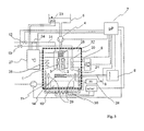
- FIG. 3 is essentially based on the high-frequency sputtering device of FIG. 1.
- FIG. 3 additionally shows a process temperature control device 27 with connected first 23, 25, second 24 and third temperature adjustment devices 26.
- the process temperature controller 27 is connected to the microprocessor 7 and can receive settings or settings for conditions for a coating process from this microprocessor.
- temperature gradients of a coating liquid in a storage container 5 and on an atomization unit 1 can be produced or compensated. Whether a temperature gradient is desired or to be prevented depends on the material used as the coating liquid or its thermal property. It can thereby influence the behavior of the coating liquid during transport or spraying suitable.
- the temperature of the coating liquid in the storage container 5 can be adjusted by means of the first temperature setting device 23.
- This is, like the other first 25, the second 24 and third 26 Temperatureinstell issued shown as a heating coil.
- this includes other heat sources, such as infrared radiators, heat exchangers, heat pumps.
- all temperature adjustment can also serve to remove heat and cooling, in which case, for example, cooling units or fans can be used.
- first temperature setting devices 23, 25 for influencing the temperature of the coating liquid are shown in FIG. 3, as many first temperature setting devices as desired may be located along the distribution system of the coating liquid.
- the distribution system essentially comprises the storage container 5, the precision pump 4, the atomization unit 1 and a tube system which connects the storage container 5 with the precision pump 4 and the precision pump 4 with the atomization unit 1.
- the capillary tube 17 and the resonator body 2 are included.
- Each of these elements of the distribution system may be provided separately with a first temperature adjustment device.
- the action of the temperature adjusting devices can take place directly, ie directly on the coating liquid.
- An example of a direct action of the first temperature adjuster 23 on the coating liquid is shown in Fig. 3 in the reservoir 5.
- a temperature adjustment such as the first temperature adjustment 25 acts on the pipe between the precision pump 4 and atomizing unit 1.
- the temperature of the coating liquid flowing through the tube is indirectly influenced.
- the temperature of the inert gas in the inert gas feed 31 can be adjusted via the second temperature adjusting device 24. Since the tempered inert gas, as it flows out of the inert gas nozzle 3 and modulates the spray pattern of the spray, interacts with the spray, the temperature of the spray that has separated from the sound box may also be adjusted.
- the spreading behavior and the condition of the spray on the substrate are also affected by the temperature prevailing in the coating chamber 32.
- This temperature can also determine the behavior of the coating during drying of the coating.
- the temperature prevailing in the coating chamber 32 can influence the thickness of the coating, in particular the coating film, on the substrate.
- a device 29 for generating an electric field This has two electrodes which are connected to a high voltage generator 28 (HV). When applying a corresponding voltage, an electric field can be generated between the electrodes in the region between the sputtering unit 1 and the substrate holder 9 together with the substrate. There are the substrate and optionally also at least a portion of the substrate holder 9 completely in the electric field, so that the field acts on the spray when adhering the sprayed particles on the substrate.
- HV high voltage generator
- a multi-channel structure is also possible.
- a plurality of devices 29 for generating an electric field are provided, which are each driven separately from the HV generator 28.
- the HV generator 28 has a connection to the microprocessor 7, via which it can be controlled by the microprocessor. In addition to electrostatic fields, it is also possible to realize time-variable electric fields with intensity changed over time or different frequency patterns.
- a magnetic field can be generated with the device 30 for generating a magnetic field between the sputtering unit 1 and the substrate holder 9 together with the substrate.
- This can be magnetostatic, i. constant or time-varying, i. Be changeable over time.
- the modulation takes over here the NF / HF generator, which is connected to the microprocessor, from which the NF / HF generator receives control signals.
- the magnetic field can be caused by means of a permanent magnet or an electromagnet.
- a permanent magnet or an electromagnet.
- FIG. 3 an electromagnet is shown.
- a U-shaped core such as a ferrite core, is on its underside, that of the resonator 2 opposite side, surrounded by an electric coil.
- magnetic field lines are formed between the parallel flanges of the core, which penetrate the space between the flanges with a magnetic field.
- the space between the sputtering unit 1 and substrate and possibly at least parts of the substrate holder 9 is penetrated by a magnetic field. This magnetic field affects the spray to be moved to the substrate.
- Both the means 28 for generating an electric field and the means 30 for generating a magnetic field can be located both within the housing 11, that is, in the coating chamber 32 or outside thereof. With a suitable choice of material for the housing 11, the electric and magnetic field in the housing 11, so from the outside into the coating chamber 32 act.
Landscapes
- Special Spraying Apparatus (AREA)
- Making Paper Articles (AREA)
- Coating By Spraying Or Casting (AREA)
- Nozzles (AREA)
- Prostheses (AREA)
- Surgical Instruments (AREA)
- Optical Record Carriers And Manufacture Thereof (AREA)
- Polishing Bodies And Polishing Tools (AREA)
- Application Of Or Painting With Fluid Materials (AREA)
Applications Claiming Priority (2)
| Application Number | Priority Date | Filing Date | Title |
|---|---|---|---|
| DE102004001095A DE102004001095A1 (de) | 2004-01-05 | 2004-01-05 | Hochfrequenzzerstäubungsvorrichtung |
| PCT/EP2005/000041 WO2005065843A1 (de) | 2004-01-05 | 2005-01-05 | Hochfrequenzzerstäubungsvorrichtung |
Publications (2)
| Publication Number | Publication Date |
|---|---|
| EP1701802A1 EP1701802A1 (de) | 2006-09-20 |
| EP1701802B1 true EP1701802B1 (de) | 2007-12-26 |
Family
ID=34706780
Family Applications (1)
| Application Number | Title | Priority Date | Filing Date |
|---|---|---|---|
| EP05700704A Expired - Lifetime EP1701802B1 (de) | 2004-01-05 | 2005-01-05 | Hochfrequenzzerstäubungsvorrichtung |
Country Status (12)
| Country | Link |
|---|---|
| US (1) | US20090032612A1 (enExample) |
| EP (1) | EP1701802B1 (enExample) |
| JP (1) | JP2007517647A (enExample) |
| CN (1) | CN100518957C (enExample) |
| AT (1) | ATE381968T1 (enExample) |
| AU (1) | AU2005203882A1 (enExample) |
| BR (1) | BRPI0506664A (enExample) |
| CA (1) | CA2549372A1 (enExample) |
| DE (2) | DE102004001095A1 (enExample) |
| ES (1) | ES2299992T3 (enExample) |
| IL (1) | IL176279A0 (enExample) |
| WO (1) | WO2005065843A1 (enExample) |
Families Citing this family (35)
| Publication number | Priority date | Publication date | Assignee | Title |
|---|---|---|---|---|
| US20060198942A1 (en) * | 2005-03-04 | 2006-09-07 | O'connor Timothy | System and method for coating a medical appliance utilizing a vibrating mesh nebulizer |
| US20060198941A1 (en) * | 2005-03-04 | 2006-09-07 | Niall Behan | Method of coating a medical appliance utilizing a vibrating mesh nebulizer, a system for coating a medical appliance, and a medical appliance produced by the method |
| WO2007066339A1 (en) * | 2005-12-07 | 2007-06-14 | Ramot At Tel Aviv University Ltd. | Drug-delivering composite structures |
| DE102006012389A1 (de) * | 2006-03-17 | 2007-09-20 | MAX-PLANCK-Gesellschaft zur Förderung der Wissenschaften e.V. | Verfahren und Vorrichtung zur Zerstäubung einer Flüssigkeit |
| US8304012B2 (en) * | 2006-05-04 | 2012-11-06 | Advanced Cardiovascular Systems, Inc. | Method for drying a stent |
| DE102007002127A1 (de) * | 2007-01-15 | 2008-07-17 | Deutsches Zentrum für Luft- und Raumfahrt e.V. | Konstruktionselement |
| JP2011504409A (ja) * | 2007-10-16 | 2011-02-10 | エイチケーピービー サイエンティフィック リミテッド | 表面コーティング方法およびその使用 |
| US8211489B2 (en) | 2007-12-19 | 2012-07-03 | Abbott Cardiovascular Systems, Inc. | Methods for applying an application material to an implantable device |
| US8361538B2 (en) | 2007-12-19 | 2013-01-29 | Abbott Laboratories | Methods for applying an application material to an implantable device |
| WO2010045468A2 (en) * | 2008-10-16 | 2010-04-22 | Applied Materials, Inc. | Methods and apparatus for recovering heat from processing systems |
| DE102010007479B3 (de) * | 2010-02-09 | 2011-06-22 | EISENMANN Anlagenbau GmbH & Co. KG, 71032 | Anlage zum Beschichten von Gegenständen |
| US20120082831A1 (en) * | 2010-10-04 | 2012-04-05 | Agiltron, Inc. | Nano-Porous Coatings and Making Methods |
| KR101263592B1 (ko) | 2011-07-25 | 2013-05-13 | 고려대학교 산학협력단 | 정전기 스프레이 장치 |
| CN102500502B (zh) * | 2011-10-10 | 2016-02-10 | 苏州科技学院 | 一种二级超声振动雾化器 |
| JP6126867B2 (ja) * | 2013-02-25 | 2017-05-10 | 東京応化工業株式会社 | 塗布装置及び塗布方法 |
| KR101440309B1 (ko) | 2013-05-06 | 2014-09-17 | 주식회사 노아닉스 | 노즐 선택형 스텐트 코팅시스템 |
| FI125920B (en) * | 2013-09-09 | 2016-04-15 | Beneq Oy | A method of coating a substrate |
| US10290519B2 (en) * | 2014-07-31 | 2019-05-14 | Katholieke Universiteit Leuven | Hot jet assisted systems and methods |
| JP6945120B2 (ja) * | 2014-08-29 | 2021-10-06 | 株式会社Flosfia | 金属膜形成方法 |
| KR102151325B1 (ko) * | 2015-12-11 | 2020-09-02 | 도시바 미쓰비시덴키 산교시스템 가부시키가이샤 | 미스트 도포 성막 장치 및 미스트 도포 성막 방법 |
| US20190210060A1 (en) * | 2016-07-11 | 2019-07-11 | Toshiba Mitsubishi-Electric Industrial Systems Corporation | Mist coating forming apparatus and mist coating forming method |
| US12097521B2 (en) | 2016-07-15 | 2024-09-24 | Transitions Optical, Ltd. | Apparatus and method for precision coating of ophthalmic lenses with photochromic coatings |
| ES2893409T3 (es) * | 2016-07-27 | 2022-02-09 | Exel Ind | Sistema de recubrimiento con cabezal de pulverización ultrasónica y campo electrostático |
| GB2555125B (en) * | 2016-10-19 | 2020-05-13 | Univ Cape Town | Coating system |
| CN107115997B (zh) * | 2017-06-16 | 2019-09-03 | 浙江吉利汽车有限公司 | 一种漆雾溢流拦截装置及风压式喷漆房 |
| CN110000142A (zh) * | 2019-04-30 | 2019-07-12 | 云谷(固安)科技有限公司 | 掩膜版清洁装置及方法 |
| CN110108150A (zh) * | 2019-06-11 | 2019-08-09 | 重庆鸿运和锐科技有限公司 | 一种提高射流喷雾塔冷效的进风布水拓扑结构装置 |
| CN110624751B (zh) * | 2019-10-31 | 2024-07-23 | 兰州理工大学 | 复合场作用下高速金属熔滴/基板碰撞装置及使用方法 |
| WO2021138715A1 (en) * | 2020-01-06 | 2021-07-15 | International Scientific Pty Ltd | Method of enhanced delivery of liquids to surfaces |
| CN112221806B (zh) * | 2020-10-10 | 2021-11-30 | 威海盛洁医疗科技有限公司 | 一种溶液分散良好的超声雾化喷涂装置及其使用方法 |
| US12420296B2 (en) * | 2021-10-06 | 2025-09-23 | Ford Motor Company | Ultrasonic atomizer for applying a coating to a substrate with electrostatic charge to prevent droplet coalescence during atomization |
| CN114345614A (zh) * | 2022-03-08 | 2022-04-15 | 深圳市库珀科技发展有限公司 | 一种用于覆膜支架的生产装置 |
| CN114308477A (zh) * | 2022-03-17 | 2022-04-12 | 深圳市库珀科技发展有限公司 | 一种用于覆膜支架的自动生产装置 |
| CN114959552B (zh) * | 2022-05-05 | 2023-12-15 | 江苏大学 | 一种球粒轰击式零件表面氮碳硼选区共渗系统及方法 |
| CN117403170B (zh) * | 2023-11-01 | 2025-06-24 | 山东万创金属科技有限公司 | 一种喷锌多孔扁管表面喷锌方法 |
Family Cites Families (17)
| Publication number | Priority date | Publication date | Assignee | Title |
|---|---|---|---|---|
| US4153201A (en) * | 1976-11-08 | 1979-05-08 | Sono-Tek Corporation | Transducer assembly, ultrasonic atomizer and fuel burner |
| JPS6059024B2 (ja) * | 1980-12-26 | 1985-12-23 | 松下電器産業株式会社 | 液体塗布装置 |
| JPS5861859A (ja) * | 1981-10-09 | 1983-04-13 | Matsushita Electric Ind Co Ltd | 液体塗布装置 |
| US4655393A (en) * | 1983-01-05 | 1987-04-07 | Sonotek Corporation | High volume ultrasonic liquid atomizer |
| CN88200648U (zh) * | 1988-01-22 | 1988-09-07 | 张树琛 | 高速粉沫摩擦喷涂机 |
| JPH03143505A (ja) * | 1989-10-30 | 1991-06-19 | Tonen Corp | 超音波濃縮装置 |
| JPH03226369A (ja) * | 1990-01-23 | 1991-10-07 | Kenji Kondo | フラックス噴霧用ノズル |
| DE4328088B4 (de) * | 1993-08-20 | 2005-05-25 | Artur Prof. Dr. Goldschmidt | Verfahren zum Beschichten von Werkstücken mit organischen Beschichtungsstoffen |
| US5451260A (en) * | 1994-04-15 | 1995-09-19 | Cornell Research Foundation, Inc. | Method and apparatus for CVD using liquid delivery system with an ultrasonic nozzle |
| JPH091004A (ja) * | 1995-06-21 | 1997-01-07 | Nissan Motor Co Ltd | エアレス方式による自動車外板のスプレー塗装方法およびスプレー塗装用塗装ガン |
| US6569249B1 (en) * | 2000-04-18 | 2003-05-27 | Clemson University | Process for forming layers on substrates |
| AU2001273276A1 (en) * | 2000-07-10 | 2002-01-21 | Epion Corporation | Improving effectiveness of medical stents by gcib |
| US6927838B2 (en) * | 2001-02-27 | 2005-08-09 | Nikon Corporation | Multiple stage, stage assembly having independent stage bases |
| US20030161937A1 (en) * | 2002-02-25 | 2003-08-28 | Leiby Mark W. | Process for coating three-dimensional substrates with thin organic films and products |
| US6789741B2 (en) * | 2002-03-27 | 2004-09-14 | S. C. Johnson & Son, Inc. | Method and apparatus for atomizing liquids having minimal droplet size |
| JP2003290699A (ja) * | 2002-03-29 | 2003-10-14 | Fuji Photo Film Co Ltd | ウエブ冷却装置 |
| DE10324415A1 (de) | 2003-05-28 | 2004-12-16 | Blue Membranes Gmbh | Verfahren zur Beschichtung von Substraten mit kohlenstoffbasiertem Material |
-
2004
- 2004-01-05 DE DE102004001095A patent/DE102004001095A1/de not_active Withdrawn
-
2005
- 2005-01-05 WO PCT/EP2005/000041 patent/WO2005065843A1/de not_active Ceased
- 2005-01-05 US US10/585,568 patent/US20090032612A1/en not_active Abandoned
- 2005-01-05 EP EP05700704A patent/EP1701802B1/de not_active Expired - Lifetime
- 2005-01-05 ES ES05700704T patent/ES2299992T3/es not_active Expired - Lifetime
- 2005-01-05 AT AT05700704T patent/ATE381968T1/de not_active IP Right Cessation
- 2005-01-05 CA CA002549372A patent/CA2549372A1/en not_active Abandoned
- 2005-01-05 CN CNB2005800019401A patent/CN100518957C/zh not_active Expired - Fee Related
- 2005-01-05 BR BRPI0506664-6A patent/BRPI0506664A/pt not_active IP Right Cessation
- 2005-01-05 AU AU2005203882A patent/AU2005203882A1/en not_active Abandoned
- 2005-01-05 DE DE502005002341T patent/DE502005002341D1/de not_active Expired - Lifetime
- 2005-01-05 JP JP2006548209A patent/JP2007517647A/ja active Pending
-
2006
- 2006-06-13 IL IL176279A patent/IL176279A0/en unknown
Also Published As
| Publication number | Publication date |
|---|---|
| DE502005002341D1 (de) | 2008-02-07 |
| BRPI0506664A (pt) | 2007-05-15 |
| JP2007517647A (ja) | 2007-07-05 |
| IL176279A0 (en) | 2006-10-05 |
| WO2005065843A1 (de) | 2005-07-21 |
| EP1701802A1 (de) | 2006-09-20 |
| AU2005203882A1 (en) | 2005-07-21 |
| ES2299992T3 (es) | 2008-06-01 |
| CA2549372A1 (en) | 2005-07-21 |
| CN100518957C (zh) | 2009-07-29 |
| US20090032612A1 (en) | 2009-02-05 |
| ATE381968T1 (de) | 2008-01-15 |
| HK1096897A1 (zh) | 2007-06-15 |
| CN1905950A (zh) | 2007-01-31 |
| DE102004001095A1 (de) | 2005-07-28 |
| KR20070000470A (ko) | 2007-01-02 |
Similar Documents
| Publication | Publication Date | Title |
|---|---|---|
| EP1701802B1 (de) | Hochfrequenzzerstäubungsvorrichtung | |
| DE102009009650B4 (de) | Verfahren und Vorrichtung zum Herstellen einer Kunststoffschicht sowie deren Verwendung | |
| DE69832069T2 (de) | Elektrospray-anordnung zur einführung von material in zellen | |
| EP2566627B1 (de) | Beschichtungseinrichtung mit zertropfenden beschichtungsmittelstrahlen | |
| DE69508770T2 (de) | Suspension plasmabeschichtung | |
| EP1675971B1 (de) | Verfahren zur beschichtung einer substratoberfläche unter verwendung eines plasmastrahles | |
| DE102016014922A1 (de) | System und Verfahren zum Flüssigprobenaufgabe für Analyseplasmaspektrometer | |
| WO2015092008A1 (de) | Vorrichtung und verfahren zum tiegelfreien schmelzen eines materials und zum zerstäuben des geschmolzenen materials zum herstellen von pulver | |
| WO2012139840A1 (de) | Vorrichtung und verfahren zum fördern von pulvern aus einem pulvervorrat | |
| WO2002048616A2 (de) | Verfahren und vorrichtung zur duftsteuerung | |
| WO2004074172A1 (ja) | 固定化方法、固定化装置および微小構造体製造方法 | |
| US20060198942A1 (en) | System and method for coating a medical appliance utilizing a vibrating mesh nebulizer | |
| EP1746357B1 (de) | Verfahren und Vorrichtung zur Erzeugung eines Feuchtluftstromes mit definierter relativer Feuchte | |
| CH676879A5 (enExample) | ||
| EP2611548A1 (de) | VORRICHTUNG UND VERFAHREN ZUM VERNEBELN ODER ZERSTÄUBEN VON FLIEßFÄHIGEN MEDIEN | |
| DE4228229C1 (de) | Verfahren und Vorrichtung zur Erzeugung von Nebeln | |
| EP3235574B1 (de) | Derivatisierungsgerät und -verfahren | |
| DE20023848U1 (de) | Vorrichtung zum Auftragen von zerstäubten Fluiden | |
| HK1096897B (en) | High frequency spraying device | |
| KR20060136440A (ko) | 고주파 스프레이장치 | |
| DE102010014552A1 (de) | Verfahren zur Plasmabeschichtung einer Substratoberfläche mit Beschichtungsflüssigkeit | |
| DE3610294A1 (de) | Verfahren zum steuern der temperatur eines stroms feiner partikel | |
| DE102014112625A1 (de) | Großflächen-Ultraschallverdampfer | |
| DE202007006399U1 (de) | Zweifrequenz bzw. Multifrequenz-Ultraschallzerstäuber | |
| DE102013106067A1 (de) | Einrichtung zum Zerstäuben viskoser Medien |
Legal Events
| Date | Code | Title | Description |
|---|---|---|---|
| PUAI | Public reference made under article 153(3) epc to a published international application that has entered the european phase |
Free format text: ORIGINAL CODE: 0009012 |
|
| 17P | Request for examination filed |
Effective date: 20060626 |
|
| AK | Designated contracting states |
Kind code of ref document: A1 Designated state(s): AT BE BG CH CY CZ DE DK EE ES FI FR GB GR HU IE IS IT LI LT LU MC NL PL PT RO SE SI SK TR |
|
| DAX | Request for extension of the european patent (deleted) | ||
| REG | Reference to a national code |
Ref country code: HK Ref legal event code: DE Ref document number: 1096897 Country of ref document: HK |
|
| RAP1 | Party data changed (applicant data changed or rights of an application transferred) |
Owner name: CINVENTION AG |
|
| GRAP | Despatch of communication of intention to grant a patent |
Free format text: ORIGINAL CODE: EPIDOSNIGR1 |
|
| RIN1 | Information on inventor provided before grant (corrected) |
Inventor name: ASGARI, SOHEIL Inventor name: RATHENOW, JOERG Inventor name: KUNSTMANN, JUERGEN |
|
| GRAS | Grant fee paid |
Free format text: ORIGINAL CODE: EPIDOSNIGR3 |
|
| GRAA | (expected) grant |
Free format text: ORIGINAL CODE: 0009210 |
|
| AK | Designated contracting states |
Kind code of ref document: B1 Designated state(s): AT BE BG CH CY CZ DE DK EE ES FI FR GB GR HU IE IS IT LI LT LU MC NL PL PT RO SE SI SK TR |
|
| REG | Reference to a national code |
Ref country code: GB Ref legal event code: FG4D Free format text: NOT ENGLISH |
|
| REG | Reference to a national code |
Ref country code: IE Ref legal event code: FG4D Free format text: LANGUAGE OF EP DOCUMENT: GERMAN |
|
| REG | Reference to a national code |
Ref country code: CH Ref legal event code: EP |
|
| REF | Corresponds to: |
Ref document number: 502005002341 Country of ref document: DE Date of ref document: 20080207 Kind code of ref document: P |
|
| GBT | Gb: translation of ep patent filed (gb section 77(6)(a)/1977) |
Effective date: 20080318 |
|
| REG | Reference to a national code |
Ref country code: SE Ref legal event code: TRGR Ref country code: CH Ref legal event code: NV Representative=s name: MAIWALD PATENTANWALTSGESELLSCHAFT (SCHWEIZ) MBH |
|
| PG25 | Lapsed in a contracting state [announced via postgrant information from national office to epo] |
Ref country code: PL Free format text: LAPSE BECAUSE OF FAILURE TO SUBMIT A TRANSLATION OF THE DESCRIPTION OR TO PAY THE FEE WITHIN THE PRESCRIBED TIME-LIMIT Effective date: 20071226 Ref country code: SI Free format text: LAPSE BECAUSE OF FAILURE TO SUBMIT A TRANSLATION OF THE DESCRIPTION OR TO PAY THE FEE WITHIN THE PRESCRIBED TIME-LIMIT Effective date: 20071226 |
|
| REG | Reference to a national code |
Ref country code: ES Ref legal event code: FG2A Ref document number: 2299992 Country of ref document: ES Kind code of ref document: T3 |
|
| REG | Reference to a national code |
Ref country code: EE Ref legal event code: FG4A Ref document number: E001954 Country of ref document: EE Effective date: 20080326 |
|
| PG25 | Lapsed in a contracting state [announced via postgrant information from national office to epo] |
Ref country code: CZ Free format text: LAPSE BECAUSE OF FAILURE TO SUBMIT A TRANSLATION OF THE DESCRIPTION OR TO PAY THE FEE WITHIN THE PRESCRIBED TIME-LIMIT Effective date: 20071226 Ref country code: IS Free format text: LAPSE BECAUSE OF FAILURE TO SUBMIT A TRANSLATION OF THE DESCRIPTION OR TO PAY THE FEE WITHIN THE PRESCRIBED TIME-LIMIT Effective date: 20080426 |
|
| PG25 | Lapsed in a contracting state [announced via postgrant information from national office to epo] |
Ref country code: MC Free format text: LAPSE BECAUSE OF NON-PAYMENT OF DUE FEES Effective date: 20080131 Ref country code: SK Free format text: LAPSE BECAUSE OF FAILURE TO SUBMIT A TRANSLATION OF THE DESCRIPTION OR TO PAY THE FEE WITHIN THE PRESCRIBED TIME-LIMIT Effective date: 20071226 Ref country code: RO Free format text: LAPSE BECAUSE OF FAILURE TO SUBMIT A TRANSLATION OF THE DESCRIPTION OR TO PAY THE FEE WITHIN THE PRESCRIBED TIME-LIMIT Effective date: 20071226 |
|
| ET | Fr: translation filed | ||
| PG25 | Lapsed in a contracting state [announced via postgrant information from national office to epo] |
Ref country code: PT Free format text: LAPSE BECAUSE OF FAILURE TO SUBMIT A TRANSLATION OF THE DESCRIPTION OR TO PAY THE FEE WITHIN THE PRESCRIBED TIME-LIMIT Effective date: 20080526 |
|
| PG25 | Lapsed in a contracting state [announced via postgrant information from national office to epo] |
Ref country code: DK Free format text: LAPSE BECAUSE OF FAILURE TO SUBMIT A TRANSLATION OF THE DESCRIPTION OR TO PAY THE FEE WITHIN THE PRESCRIBED TIME-LIMIT Effective date: 20071226 |
|
| REG | Reference to a national code |
Ref country code: HK Ref legal event code: GR Ref document number: 1096897 Country of ref document: HK |
|
| PLBE | No opposition filed within time limit |
Free format text: ORIGINAL CODE: 0009261 |
|
| STAA | Information on the status of an ep patent application or granted ep patent |
Free format text: STATUS: NO OPPOSITION FILED WITHIN TIME LIMIT |
|
| 26N | No opposition filed |
Effective date: 20080929 |
|
| REG | Reference to a national code |
Ref country code: EE Ref legal event code: HC1A Ref document number: E001954 Country of ref document: EE |
|
| PG25 | Lapsed in a contracting state [announced via postgrant information from national office to epo] |
Ref country code: GR Free format text: LAPSE BECAUSE OF FAILURE TO SUBMIT A TRANSLATION OF THE DESCRIPTION OR TO PAY THE FEE WITHIN THE PRESCRIBED TIME-LIMIT Effective date: 20080327 |
|
| PGFP | Annual fee paid to national office [announced via postgrant information from national office to epo] |
Ref country code: EE Payment date: 20081208 Year of fee payment: 5 Ref country code: IE Payment date: 20081217 Year of fee payment: 5 Ref country code: LT Payment date: 20081205 Year of fee payment: 5 |
|
| PGFP | Annual fee paid to national office [announced via postgrant information from national office to epo] |
Ref country code: ES Payment date: 20081210 Year of fee payment: 5 |
|
| PG25 | Lapsed in a contracting state [announced via postgrant information from national office to epo] |
Ref country code: BG Free format text: LAPSE BECAUSE OF FAILURE TO SUBMIT A TRANSLATION OF THE DESCRIPTION OR TO PAY THE FEE WITHIN THE PRESCRIBED TIME-LIMIT Effective date: 20080326 Ref country code: AT Free format text: LAPSE BECAUSE OF NON-PAYMENT OF DUE FEES Effective date: 20080105 |
|
| PGFP | Annual fee paid to national office [announced via postgrant information from national office to epo] |
Ref country code: LU Payment date: 20090130 Year of fee payment: 5 |
|
| PGFP | Annual fee paid to national office [announced via postgrant information from national office to epo] |
Ref country code: FI Payment date: 20090109 Year of fee payment: 5 |
|
| PG25 | Lapsed in a contracting state [announced via postgrant information from national office to epo] |
Ref country code: CY Free format text: LAPSE BECAUSE OF FAILURE TO SUBMIT A TRANSLATION OF THE DESCRIPTION OR TO PAY THE FEE WITHIN THE PRESCRIBED TIME-LIMIT Effective date: 20071226 |
|
| PGFP | Annual fee paid to national office [announced via postgrant information from national office to epo] |
Ref country code: BE Payment date: 20090102 Year of fee payment: 5 |
|
| REG | Reference to a national code |
Ref country code: CH Ref legal event code: PFA Owner name: CINVENTION AG Free format text: CINVENTION AG#RHEINGAUSTRASSE 190-196#65203 WIESBADEN (DE) -TRANSFER TO- CINVENTION AG#RHEINGAUSTRASSE 190-196#65203 WIESBADEN (DE) |
|
| PGFP | Annual fee paid to national office [announced via postgrant information from national office to epo] |
Ref country code: CH Payment date: 20100125 Year of fee payment: 6 |
|
| PGFP | Annual fee paid to national office [announced via postgrant information from national office to epo] |
Ref country code: FR Payment date: 20100219 Year of fee payment: 6 |
|
| PGFP | Annual fee paid to national office [announced via postgrant information from national office to epo] |
Ref country code: DE Payment date: 20100129 Year of fee payment: 6 Ref country code: GB Payment date: 20100113 Year of fee payment: 6 |
|
| PG25 | Lapsed in a contracting state [announced via postgrant information from national office to epo] |
Ref country code: HU Free format text: LAPSE BECAUSE OF FAILURE TO SUBMIT A TRANSLATION OF THE DESCRIPTION OR TO PAY THE FEE WITHIN THE PRESCRIBED TIME-LIMIT Effective date: 20080627 |
|
| BERE | Be: lapsed |
Owner name: CINVENTION A.G. Effective date: 20100131 |
|
| LTLA | Lt: lapse of european patent or patent extension |
Effective date: 20100105 |
|
| PG25 | Lapsed in a contracting state [announced via postgrant information from national office to epo] |
Ref country code: TR Free format text: LAPSE BECAUSE OF FAILURE TO SUBMIT A TRANSLATION OF THE DESCRIPTION OR TO PAY THE FEE WITHIN THE PRESCRIBED TIME-LIMIT Effective date: 20071226 |
|
| PGFP | Annual fee paid to national office [announced via postgrant information from national office to epo] |
Ref country code: NL Payment date: 20081231 Year of fee payment: 6 |
|
| REG | Reference to a national code |
Ref country code: EE Ref legal event code: MM4A Ref document number: E001954 Country of ref document: EE Effective date: 20100131 |
|
| PG25 | Lapsed in a contracting state [announced via postgrant information from national office to epo] |
Ref country code: LT Free format text: LAPSE BECAUSE OF NON-PAYMENT OF DUE FEES Effective date: 20100105 Ref country code: EE Free format text: LAPSE BECAUSE OF NON-PAYMENT OF DUE FEES Effective date: 20100131 |
|
| PG25 | Lapsed in a contracting state [announced via postgrant information from national office to epo] |
Ref country code: FI Free format text: LAPSE BECAUSE OF NON-PAYMENT OF DUE FEES Effective date: 20100105 |
|
| PGFP | Annual fee paid to national office [announced via postgrant information from national office to epo] |
Ref country code: SE Payment date: 20100125 Year of fee payment: 6 |
|
| PG25 | Lapsed in a contracting state [announced via postgrant information from national office to epo] |
Ref country code: IE Free format text: LAPSE BECAUSE OF NON-PAYMENT OF DUE FEES Effective date: 20100105 |
|
| PG25 | Lapsed in a contracting state [announced via postgrant information from national office to epo] |
Ref country code: BE Free format text: LAPSE BECAUSE OF NON-PAYMENT OF DUE FEES Effective date: 20100131 |
|
| REG | Reference to a national code |
Ref country code: ES Ref legal event code: FD2A Effective date: 20110310 |
|
| PG25 | Lapsed in a contracting state [announced via postgrant information from national office to epo] |
Ref country code: ES Free format text: LAPSE BECAUSE OF NON-PAYMENT OF DUE FEES Effective date: 20110309 |
|
| PGFP | Annual fee paid to national office [announced via postgrant information from national office to epo] |
Ref country code: IT Payment date: 20100125 Year of fee payment: 6 |
|
| REG | Reference to a national code |
Ref country code: NL Ref legal event code: V1 Effective date: 20110801 |
|
| REG | Reference to a national code |
Ref country code: CH Ref legal event code: PL |
|
| REG | Reference to a national code |
Ref country code: SE Ref legal event code: EUG |
|
| GBPC | Gb: european patent ceased through non-payment of renewal fee |
Effective date: 20110105 |
|
| PG25 | Lapsed in a contracting state [announced via postgrant information from national office to epo] |
Ref country code: ES Free format text: LAPSE BECAUSE OF NON-PAYMENT OF DUE FEES Effective date: 20100106 |
|
| REG | Reference to a national code |
Ref country code: FR Ref legal event code: ST Effective date: 20110930 |
|
| PG25 | Lapsed in a contracting state [announced via postgrant information from national office to epo] |
Ref country code: CH Free format text: LAPSE BECAUSE OF NON-PAYMENT OF DUE FEES Effective date: 20110131 Ref country code: LI Free format text: LAPSE BECAUSE OF NON-PAYMENT OF DUE FEES Effective date: 20110131 Ref country code: FR Free format text: LAPSE BECAUSE OF NON-PAYMENT OF DUE FEES Effective date: 20110131 |
|
| PG25 | Lapsed in a contracting state [announced via postgrant information from national office to epo] |
Ref country code: GB Free format text: LAPSE BECAUSE OF NON-PAYMENT OF DUE FEES Effective date: 20110105 |
|
| REG | Reference to a national code |
Ref country code: DE Ref legal event code: R119 Ref document number: 502005002341 Country of ref document: DE Effective date: 20110802 |
|
| PG25 | Lapsed in a contracting state [announced via postgrant information from national office to epo] |
Ref country code: IT Free format text: LAPSE BECAUSE OF NON-PAYMENT OF DUE FEES Effective date: 20110105 Ref country code: NL Free format text: LAPSE BECAUSE OF NON-PAYMENT OF DUE FEES Effective date: 20110801 |
|
| PG25 | Lapsed in a contracting state [announced via postgrant information from national office to epo] |
Ref country code: LU Free format text: LAPSE BECAUSE OF NON-PAYMENT OF DUE FEES Effective date: 20100105 |
|
| PG25 | Lapsed in a contracting state [announced via postgrant information from national office to epo] |
Ref country code: SE Free format text: LAPSE BECAUSE OF NON-PAYMENT OF DUE FEES Effective date: 20110106 |
|
| PG25 | Lapsed in a contracting state [announced via postgrant information from national office to epo] |
Ref country code: DE Free format text: LAPSE BECAUSE OF NON-PAYMENT OF DUE FEES Effective date: 20110802 |