EP1700975A1 - Scaffold mountable in window opening - Google Patents
Scaffold mountable in window opening Download PDFInfo
- Publication number
- EP1700975A1 EP1700975A1 EP06290190A EP06290190A EP1700975A1 EP 1700975 A1 EP1700975 A1 EP 1700975A1 EP 06290190 A EP06290190 A EP 06290190A EP 06290190 A EP06290190 A EP 06290190A EP 1700975 A1 EP1700975 A1 EP 1700975A1
- Authority
- EP
- European Patent Office
- Prior art keywords
- vertical
- horizontal
- opening
- scaffolding
- platform
- Prior art date
- Legal status (The legal status is an assumption and is not a legal conclusion. Google has not performed a legal analysis and makes no representation as to the accuracy of the status listed.)
- Granted
Links
- 230000000712 assembly Effects 0.000 claims description 8
- 238000000429 assembly Methods 0.000 claims description 8
- 230000004888 barrier function Effects 0.000 claims description 2
- 239000000872 buffer Substances 0.000 description 3
- 241001080024 Telles Species 0.000 description 2
- 230000000903 blocking effect Effects 0.000 description 1
- 239000000463 material Substances 0.000 description 1
- 230000000284 resting effect Effects 0.000 description 1
Images

Classifications
-
- E—FIXED CONSTRUCTIONS
- E04—BUILDING
- E04G—SCAFFOLDING; FORMS; SHUTTERING; BUILDING IMPLEMENTS OR AIDS, OR THEIR USE; HANDLING BUILDING MATERIALS ON THE SITE; REPAIRING, BREAKING-UP OR OTHER WORK ON EXISTING BUILDINGS
- E04G3/00—Scaffolds essentially supported by building constructions, e.g. adjustable in height
- E04G3/18—Scaffolds essentially supported by building constructions, e.g. adjustable in height supported by cantilevers or other provisions mounted in openings in the building, e.g. window openings
-
- E—FIXED CONSTRUCTIONS
- E04—BUILDING
- E04G—SCAFFOLDING; FORMS; SHUTTERING; BUILDING IMPLEMENTS OR AIDS, OR THEIR USE; HANDLING BUILDING MATERIALS ON THE SITE; REPAIRING, BREAKING-UP OR OTHER WORK ON EXISTING BUILDINGS
- E04G3/00—Scaffolds essentially supported by building constructions, e.g. adjustable in height
- E04G3/28—Mobile scaffolds; Scaffolds with mobile platforms
Definitions
- the present invention relates to work platform supports and more particularly to external scaffolds.
- a scaffolding able to bear on a substantially vertical wall having an outer face and an inner face, delimiting an inner zone and an outer zone, in which is formed at least one opening with which said scaffolding cooperates.
- Such scaffolds are used when working on an exterior wall.
- scaffolding is maintained by cooperating with one or more openings in a wall, such as windows.
- US 4,079,813 describes a folding scaffold able to cooperate with a single window supported on the outer and inner faces of the wall.
- This scaffolding has two major drawbacks: on the one hand, the platform has a very small surface, which limits the number of people who can climb on the platform as well as the useful surface, and on the other hand, it does not It is not possible to adjust the vertical position of the platform, which may prevent a worker from accessing the area above the window bay.
- the document FR 959 745 represents a scaffolding of windows able to cooperate with two windows, whose platform also has the disadvantage, when the scaffolding is installed, not being able to be adjustable in height.
- the object of the invention is to provide a scaffold substantially free from the disadvantages mentioned above.
- the vertical position of the platform can be adjusted so that the user can access a larger wall surface than in the case where the platform is fixed.
- each opening cooperates with a fixing element and the horizontal platform of the scaffolding is supported by the horizontal branches of the brackets of the fastening assemblies.
- angles are adjustable in height, it is not necessary that the lower edges of the openings are arranged on the same height because it is always possible to position the platform horizontally by adjusting the vertical position of each horizontal branch supporting the plate -form.
- the multiple support means give the scaffold a certain stability.
- an already known scaffold tends to pivot about a horizontal axis passing through lower support means.
- the judicious position of the first and second support means prevents this pivoting by bearing on the outer and inner faces of the wall, respectively below and above the opening so as to block the pivoting of the scaffolding .
- the inner vertical bar further comprises third support means adapted to bear on the inner face of the wall, below the opening.
- the third support means are located at a height between that of the lower edge of the opening and that of the first support means.
- the second and third support means are located at both ends of the inner vertical bar.
- the horizontal bar further comprises fourth support means adapted to take up vertically on a lower edge of an opening.
- these fourth support means are used to lock the scaffold vertically. In particular, they prevent the scaffold from moving down due to the scaffold's own weight and / or the weight of the user, which allows the scaffold to be used safely.
- the first, second, third and fourth bearing means comprise at least one adjustable rubber support pad.
- the rubber prevents the pad from slipping on the wall, transversely to the direction of support. Any other material with a high coefficient of friction may be used.
- the platform is able to be positioned below the level of the lower edge of an opening.
- the user can easily access the portion below the opening, without having to disassemble or move the scaffold.
- the platform is able to be positioned above the level of the upper rim of an opening.
- the user has the opportunity to access the portion above the opening, without having to disassemble or move the scaffold.
- the vertical branch of a bracket is able to slide vertically in a channel formed in the outer vertical bar.
- the channel preferably extends along the outer vertical bar, so that the vertical leg can slide vertically over the entire length of the outer vertical bar.
- the vertical leg comprises a plurality of fastening means adapted to cooperate with fastening means disposed on the outer vertical bar so as to fix the vertical leg in the channel of different heights.
- the angle can be positioned in at least two ways relative to the outer vertical bar so that the horizontal leg can be disposed either above or below the vertical leg.
- the scaffold comprises at least two fastening assemblies.
- each fastener cooperates with an opening formed in the wall, but however, two fastener assemblies can cooperate with one and the same opening.
- the scaffolding cooperates with two openings formed in the wall and disposed substantially at the same height.
- the scaffolding preferably comprises two sets of separate fasteners, the platform is supported by the two horizontal branches of the two angles of two sets of fastening cooperating with the two openings and that the position of the platform is adjustable in a vertical direction.
- Adjusting the vertical position of the platform is done by positioning the angles so that their horizontal branches are arranged in the same horizontal plane.
- the scaffolding is able to cooperate with two, three or more openings provided they are arranged at about the same height.
- the scaffold 10 shown here is designed to cooperate with two windows bays 12, 14 formed substantially at the same height in an exterior wall 16 of a house.
- the scaffold 10 cooperated with a single opening, or with a plurality of openings disposed substantially at the same height.
- the two window openings 12, 14 have different dimensions and their lower edges are not arranged in the same horizontal plane.
- This representation makes it possible to clearly show the adaptability of the scaffolding according to the invention to any type of window bays.
- the scaffold according to the invention advantageously allows to cooperate with several openings arranged substantially but not exactly the same height.
- the scaffold 10 supports a horizontal platform 18 which extends along the wall 16 in a plane substantially orthogonal to the surface of the wall for a distance between the vertical edges furthest from the two openings 12, 14 forming the bays. window 12,14.
- This platform 18 is intended to support one or more users 20.
- the horizontal platform 18 is supported by two fastening assemblies 22,24 disposed substantially at each end of said platform and each cooperating with a window opening.
- the scaffold 10 according to the invention bears on the outside face of the wall 16 and, consequently, it is not necessary for the scaffolding 10 to bear on the ground.
- each fastening element 22,24 is intended to cooperate with a window bay so as to be secured to the wall 16.
- each fastening element 22,24 is adapted to bear against the outer faces 25 and 27 of inner wall 16.
- Each fastener 22,24 comprises an outer vertical bar 26 whose lower end comprises first bearing means 28 preferably comprising a pair of rubber bearing pads 28a, each of the bearing pads preferably having the shape of a thick disc forming a bearing surface disposed in a substantially vertical plane.
- the fastening element 22 further comprises an inner vertical bar 29 which has second support means 32 at its upper end and third support means 34 at its lower end.
- the length of the inner vertical bar 29 can be adjusted by means of a vertical telescopic arm 29 ', which is integral with the inner vertical bar, in which it slides by means of a screw 60 clamping.
- the second support means 32 comprise a pair of rubber bearing pads 32a, each of the support pads also preferably having the form of thick discs forming bearing surfaces disposed in a substantially vertical plane.
- the second support means 32 may comprise an additional pair of rubber bearing pads 33a, each of the support pads preferably being in the form of thick discs forming bearing surfaces disposed in a substantially horizontal plane.
- the third support means 34 comprise a pair of rubber bearing pads 34a, each of the support pads preferably being in the form of thick discs forming bearing surfaces disposed in a substantially vertical plane.
- the clamping screw 60 may comprise at its end a bearing pad 60a similar to those described above.
- the bearing pads 28a, 32a, 34a of the first, second and third bearing means and the bearing pad 60a associated with the clamping screw 60, are arranged in such a way that their respective bearing surfaces are in contact with each other. -a-vis.
- the outer 26 and inner 29 vertical bars are integrally connected together via the ends of a transverse horizontal bar 36.
- the horizontal bar 36 is fixed substantially preferentially to two-thirds of the length of the inner vertical bar 29.
- the horizontal bar 36 is fixed substantially to two-thirds of the length of the outer vertical bar 26.
- the length of the horizontal bar 36 can be adjusted, preferably by means of a telescopic arm 36 ' visible in Figure 2, so as to adapt the fastener to the thickness of the wall 16.
- the second support means 32 it is advantageous for the second support means 32 to be positioned between the horizontal bar 36 and the first support means 28, as shown in FIG . 2.
- the horizontal bar 36 preferably but not necessarily has fourth bearing means 30 comprising a rubber bearing pad 30a having the shape of a thick disk forming a bearing surface disposed in a substantially horizontal plane whose function will be explained. below.
- Each fastening element further comprises an angle bracket 38 adjustably fixed to the outer vertical bar 26.
- This bracket 38 comprises a horizontal branch 40 and a vertical branch 42 able to slide vertically in a channel 44 formed in the outer vertical bar 26.
- the outer vertical bar 26 has, in a transverse plane, a section substantially shaped "U".
- the outer vertical bar 26 has a plurality of transverse bores 45 disposed periodically over substantially its entire length.
- the vertical leg 42 of the bracket 38 also has a plurality of transverse bores (not shown here) and the fixing of the outer vertical bar 26 with the vertical leg 42 of the bracket 38 can be achieved with pins 47 traversing transversely said vertical bar 26 and said branch 42 through said bores.
- the horizontal leg 40 of the bracket 38 is intended to support the platform 18. More specifically, it is the two horizontal branches 40,40 ' of the two brackets 38,38' of two sets of fasteners 22,24 that support the platform 18.
- the horizontal branch 40 of the bracket 38 is advantageously unfoldable in the direction of its length so as to adapt to the width of the platform 18.
- the horizontal leg 40 comprises a telescopic arm 46 which is provided at its end with a vertical rod holder 48, intended to hold one of the two horizontal arms of a barrier 50 forming guardrails, shown in FIG .
- Figure 3 shows a sectional side view of the window bay on which is mounted a fastener 22,24.
- the wall 16 of the house shown in this figure delimits an inner zone 52 and an outer zone 54.
- the outer vertical bar 26 is disposed in the outer zone 54, the rubber pad 28a of the first support means being disposed below the window bay.
- the inner vertical bar 29 is disposed in the inner zone 52, the buffer 32a of the second support means 32 bearing above the window bay and the buffers 34a of the third support means 34 bearing support below the window bay. It is therefore understood that the inner vertical bar 29 preferably has a length substantially greater than the height of the window bay.
- the fixing element 22 is arranged so that the horizontal bar 36 passes through the window bay, and the buffer 30 of the fourth support means is arranged to bear on a lower edge 56 of the window bay .
- the assembly formed by the rubber bearing pads 28a, 32a of the first and second support means 28, 32 allows advantageously to prevent the fastening element 22 from pivoting in a counterclockwise direction.
- the assembly formed by the rubber support pads 28a, 34a of the first and third support means 28,34 advantageously allows to tighten the clamp part of the wall that lies beneath the window opening.
- the third support means 34 are not systematically necessary, however they improve the blocking of the scaffolding by providing additional support and improves the safety of the scaffolding.
- the rubber pad 30a of the fourth support means 30 for their part makes it possible to lock the fastening element vertically 22 by resting on the lower edge of the window bay.
- the fourth support means 30 can be horizontally displaceable in the direction of the transverse horizontal bar 36, so as to be able to adapt to the shape of the lower edge, for example 56.
- the support pad 60a associated with the clamping screw 60 is arranged so as to be able to bear on the inside face 27 of the wall 16 , above the bay of window 12.
- the support pads 33a located at the upper end of the inner vertical bar 29 and arranged in a horizontal plane, are able to bear against a ceiling 17.
- all the support means are adjustable vertically and / or horizontally so as to adapt to the shape of the outer and inner faces of the wall 16, and the lower edge of the window bay.
- the angle 38 can be positioned at least two ways with respect to the outer vertical bar so that the horizontal leg 40 can be disposed either above or below the vertical leg 44.
- the angle is positioned in such a way that the horizontal branch 40 is disposed above the vertical branch 42.
- the angle is positioned so that the horizontal leg 40 is disposed below the vertical leg.
- the angle 38 is fixed to the lower end of the outer vertical bar 26 so that it is no longer possible to lower the vertical leg 42 of the bracket 38.
Landscapes
- Engineering & Computer Science (AREA)
- Architecture (AREA)
- Mechanical Engineering (AREA)
- Civil Engineering (AREA)
- Structural Engineering (AREA)
- Ladders (AREA)
- Glass Compositions (AREA)
- Wing Frames And Configurations (AREA)
- Electrical Discharge Machining, Electrochemical Machining, And Combined Machining (AREA)
- Farming Of Fish And Shellfish (AREA)
- Special Wing (AREA)
Abstract
Description
La présente invention concerne les supports de plate-forme de travail et plus particulièrement les échafaudages extérieurs.The present invention relates to work platform supports and more particularly to external scaffolds.
Elle concerne plus précisément un échafaudage apte à prendre appui sur un mur substantiellement vertical comportant une face extérieure et une face intérieure, délimitant une zone intérieure et une zone extérieure, dans lequel est ménagé au moins une ouverture avec laquelle ledit échafaudage coopère.It concerns more precisely a scaffolding able to bear on a substantially vertical wall having an outer face and an inner face, delimiting an inner zone and an outer zone, in which is formed at least one opening with which said scaffolding cooperates.
En général, de tels échafaudages sont utilisés lors de travaux effectués sur un mur extérieur.In general, such scaffolds are used when working on an exterior wall.
Contrairement aux échafaudages traditionnels qui prennent appui sur la surface du sol, de tels échafaudages sont maintenus grâce au fait qu'ils coopèrent avec une ou plusieurs ouvertures disposées dans un mur, telles des baies de fenêtres.Unlike traditional scaffolds that rest on the ground surface, such scaffolding is maintained by cooperating with one or more openings in a wall, such as windows.
Le document US 4 079 813 décrit un échafaudage repliable apte à coopérer avec une unique fenêtre en prenant appui sur les faces extérieure et intérieure du mur.US 4,079,813 describes a folding scaffold able to cooperate with a single window supported on the outer and inner faces of the wall.
Cet échafaudage présente deux inconvénients majeurs : d'une part la plate-forme présente une surface très réduite, ce qui limite le nombre de personnes pouvant monter sur la plate-forme ainsi que la surface utile, et d'autre part, il n'est pas possible de régler la position verticale de la plate-forme, ce qui peut empêcher un ouvrier d'accéder à la partie située au dessus de la baie de fenêtre.This scaffolding has two major drawbacks: on the one hand, the platform has a very small surface, which limits the number of people who can climb on the platform as well as the useful surface, and on the other hand, it does not It is not possible to adjust the vertical position of the platform, which may prevent a worker from accessing the area above the window bay.
Le document FR 959 745 représente quant à lui un échafaudage de fenêtres apte à coopérer avec deux fenêtres, dont la plate-forme présente également l'inconvénient, lorsque l'échafaudage est installé, de ne pas pouvoir être réglable en hauteur.The document FR 959 745 represents a scaffolding of windows able to cooperate with two windows, whose platform also has the disadvantage, when the scaffolding is installed, not being able to be adjustable in height.
En outre, il est nécessaire que les bords des fenêtres soient disposés à une même hauteur, ce qui n'est pas toujours le cas en pratique.In addition, it is necessary that the edges of the windows are arranged at the same height, which is not always the case in practice.
L'invention a pour but de fournir un échafaudage substantiellement exempt des inconvénients cités ci-dessus.The object of the invention is to provide a scaffold substantially free from the disadvantages mentioned above.
Le but est atteint par le fait que l'échafaudage selon l'invention comprend au moins un élément de fixation comportant :
- une barre verticale extérieure située dans la zone extérieure comportant des premiers moyens d'appui aptes à prendre appui contre la face extérieure du mur, en dessous de l'ouverture ;
- une barre verticale intérieure située dans la zone intérieure, comportant des deuxièmes moyens d'appui aptes à prendre appui contre la face intérieure du mur, au dessus de l'ouverture ;
- une barre horizontale transversale fixée aux barres verticales intérieure et extérieure, et traversant le mur par l'ouverture ;
- une cornière fixée de manière réglable verticalement à la barre verticale extérieure, comportant une branche verticale et une branche horizontale apte à soutenir une plate-forme horizontale.
- an outer vertical bar located in the outer zone comprising first support means able to bear against the outer face of the wall, below the opening;
- an inner vertical bar located in the inner zone, comprising second support means able to bear against the inner face of the wall, above the opening;
- a transverse horizontal bar attached to the inner and outer vertical bars, and passing through the wall through the opening;
- a bracket fixed vertically adjustable to the outer vertical bar, having a vertical leg and a horizontal branch adapted to support a horizontal platform.
Ainsi, la position verticale de la plate-forme peut être réglée de façon que l'utilisateur puisse accéder à une plus grande surface de mur que dans le cas où la plate-forme est fixe.Thus, the vertical position of the platform can be adjusted so that the user can access a larger wall surface than in the case where the platform is fixed.
On comprend que l'échafaudage selon l'invention peut coopérer avec plusieurs ouvertures. Dans ce cas, chaque ouverture coopère avec un élément de fixation et la plate-forme horizontale de l'échafaudage est soutenue par les branches horizontales des cornières des ensembles de fixation.It is understood that the scaffold according to the invention can cooperate with several openings. In this case, each opening cooperates with a fixing element and the horizontal platform of the scaffolding is supported by the horizontal branches of the brackets of the fastening assemblies.
Comme les cornières sont réglables en hauteur, il n'est pas nécessaire que les bords inférieurs des ouvertures soient disposés sur une même hauteur car il est toujours possible de positionner horizontalement la plate-forme en réglant la position verticale de chaque branche horizontale supportant la plate-forme.As the angles are adjustable in height, it is not necessary that the lower edges of the openings are arranged on the same height because it is always possible to position the platform horizontally by adjusting the vertical position of each horizontal branch supporting the plate -form.
On comprend en outre que les multiples moyens d'appui confèrent à l'échafaudage une stabilité certaine.It is further understood that the multiple support means give the scaffold a certain stability.
Lorsqu'un ouvrier se trouve sur la plate-forme, un échafaudage déjà connu a tendance à pivoter autour d'un axe horizontal passant par des moyens d'appui inférieurs.When a worker is on the platform, an already known scaffold tends to pivot about a horizontal axis passing through lower support means.
La position judicieuse des premiers et deuxièmes moyens d'appui permet d'empêcher ce pivotement en prenant appui sur les faces extérieure et intérieure du mur, respectivement en dessous et au-dessus de l'ouverture de manière à bloquer le pivotement de l'échafaudage.The judicious position of the first and second support means prevents this pivoting by bearing on the outer and inner faces of the wall, respectively below and above the opening so as to block the pivoting of the scaffolding .
Avantageusement, la barre verticale intérieure comporte en outre des troisièmes moyens d'appui aptes à prendre appui sur la face intérieure du mur, en dessous de l'ouverture.Advantageously, the inner vertical bar further comprises third support means adapted to bear on the inner face of the wall, below the opening.
De préférence, les troisièmes moyens d'appui sont situés à une hauteur comprise entre celle du bord inférieur de l'ouverture et celle des premiers moyens d'appui.Preferably, the third support means are located at a height between that of the lower edge of the opening and that of the first support means.
On comprend que ces troisièmes moyens d'appui améliorent le blocage de l'échafaudage par rapport au mur avec lequel il coopère, et donc, améliore la sécurité de l'échafaudage.It is understood that these third support means improve the locking of the scaffold relative to the wall with which it cooperates, and thus, improves the safety of the scaffolding.
De préférence, les deuxièmes et troisièmes moyens d'appui sont situés aux deux extrémités de la barre verticale intérieure.Preferably, the second and third support means are located at both ends of the inner vertical bar.
Avantageusement, la barre horizontale comporte en outre des quatrième moyens d'appui aptes à prendre verticalement appui sur un bord inférieur d'une ouverture.Advantageously, the horizontal bar further comprises fourth support means adapted to take up vertically on a lower edge of an opening.
On comprend que ces quatrième moyens d'appui permettent de bloquer verticalement l'échafaudage. En particulier, ils empêchent le déplacement vers le bas de l'échafaudage dû au poids propre de l'échafaudage et/ou au poids de l'utilisateur, ce qui permet d'utiliser l'échafaudage en toute sécurité.It is understood that these fourth support means are used to lock the scaffold vertically. In particular, they prevent the scaffold from moving down due to the scaffold's own weight and / or the weight of the user, which allows the scaffold to be used safely.
De préférence, les premiers, deuxièmes, troisièmes et quatrièmes moyens d'appui comportent au moins un tampon d'appui réglable en caoutchouc.Preferably, the first, second, third and fourth bearing means comprise at least one adjustable rubber support pad.
On comprend que le caoutchouc permet d'éviter que le tampon ne glisse sur le mur, transversalement à la direction d'appui. On peut utiliser tout autre matériau à fort coefficient de frottement.It is understood that the rubber prevents the pad from slipping on the wall, transversely to the direction of support. Any other material with a high coefficient of friction may be used.
Avantageusement, la plate-forme est apte à être positionnée en dessous du niveau du bord inférieur d'une ouverture.Advantageously, the platform is able to be positioned below the level of the lower edge of an opening.
Ainsi, l'utilisateur peut aisément accéder à la partie située en dessous de l'ouverture, sans devoir démonter ou déplacer l'échafaudage.Thus, the user can easily access the portion below the opening, without having to disassemble or move the scaffold.
Avantageusement, la plate-forme est apte à être positionnée au dessus du niveau du rebord supérieur d'une ouverture.Advantageously, the platform is able to be positioned above the level of the upper rim of an opening.
Ainsi, l'utilisateur a la possibilité d'accéder à la partie située au dessus de l'ouverture, sans avoir à démonter ou déplacer l'échafaudage.Thus, the user has the opportunity to access the portion above the opening, without having to disassemble or move the scaffold.
Avantageusement, la branche verticale d'une cornière est apte à coulisser verticalement dans un canal formé dans la barre verticale extérieure.Advantageously, the vertical branch of a bracket is able to slide vertically in a channel formed in the outer vertical bar.
Le canal s'étend préférentiellement le long de la barre verticale extérieure, de sorte que la branche verticale puisse coulisser verticalement sur toute la longueur de la barre verticale extérieure.The channel preferably extends along the outer vertical bar, so that the vertical leg can slide vertically over the entire length of the outer vertical bar.
De préférence, la branche verticale comporte une pluralité de moyens de fixation aptes à coopérer avec des moyens de fixation disposés sur la barre verticale extérieure de manière à fixer la branche verticale dans le canal de différentes hauteurs.Preferably, the vertical leg comprises a plurality of fastening means adapted to cooperate with fastening means disposed on the outer vertical bar so as to fix the vertical leg in the channel of different heights.
On comprend alors qu'il est possible de positionner la cornière à différentes hauteurs et, par suite, qu'il est aisé de régler la position verticale de la plate-forme depuis une position située en dessous de l'ouverture jusqu'à une position située au-dessus de l'ouverture.It is then understood that it is possible to position the angle at different heights and, therefore, that it is easy to adjust the vertical position of the platform from a position below the opening to a position located above the opening.
Avantageusement, la cornière peut être positionnée au moins de deux façons par rapport à la barre verticale extérieure de sorte que la branche horizontale peut être disposée soit au dessus soit en dessous de la branche verticale.Advantageously, the angle can be positioned in at least two ways relative to the outer vertical bar so that the horizontal leg can be disposed either above or below the vertical leg.
Ainsi, sans changer la position de fixation de la branche verticale, on dispose de deux positions pour la plate-forme : une position haute lorsque la branche horizontale est située au dessus de la branche verticale, et une position basse lorsque la branche horizontale est située en dessous de la branche verticale.Thus, without changing the fixing position of the vertical branch, there are two positions for the platform: a high position when the horizontal branch is located above the vertical branch, and a low position when the horizontal branch is located below the vertical branch.
Ces deux positions sont particulièrement intéressantes dès lors qu'il est nécessaire de positionner la plate-forme dans une position extrême haute ou dans une position extrême basse, en particulier pour atteindre les parties situées au-dessus et en dessous de l'ouverture.These two positions are particularly interesting when it is necessary to position the platform in an extreme high position or in an extreme low position, in particular to reach the parts above and below the opening.
Selon un mode avantageux de réalisation de l'invention, l'échafaudage comprend au moins deux ensembles de fixation.According to an advantageous embodiment of the invention, the scaffold comprises at least two fastening assemblies.
Préférentiellement, on comprend que chaque élément de fixation coopère avec une ouverture formée dans le mur, mais toutefois, deux ensembles de fixation peuvent coopérer avec une seule et même ouverture.Preferably, it is understood that each fastener cooperates with an opening formed in the wall, but however, two fastener assemblies can cooperate with one and the same opening.
Préférentiellement, l'échafaudage coopère avec deux ouvertures formées dans le mur et disposées sensiblement à la même hauteur.Preferably, the scaffolding cooperates with two openings formed in the wall and disposed substantially at the same height.
Ainsi, on comprend que l'échafaudage comporte de préférence deux ensembles de fixations distincts, que la plate-forme est soutenue par les deux branches horizontales des deux cornières des deux ensembles de fixation coopérant avec les deux ouvertures et que la position de la plate-forme est réglable selon une direction verticale.Thus, it is understood that the scaffolding preferably comprises two sets of separate fasteners, the platform is supported by the two horizontal branches of the two angles of two sets of fastening cooperating with the two openings and that the position of the platform is adjustable in a vertical direction.
Le réglage de la position verticale de la plate-forme se fait en positionnant les cornières de façon que leurs branches horizontales soient disposées dans un même plan horizontal.Adjusting the vertical position of the platform is done by positioning the angles so that their horizontal branches are arranged in the same horizontal plane.
Sans sortir de l'invention, on comprend que l'échafaudage est apte à coopérer avec deux, trois ou davantage d'ouvertures pourvu qu'elles soient disposées environ à la même hauteur.Without departing from the invention, it is understood that the scaffolding is able to cooperate with two, three or more openings provided they are arranged at about the same height.
L'invention sera bien comprise et ses avantages apparaîtront mieux à la lecture de la description détaillée qui suit, d'un mode de réalisation représenté à titre d'exemple non limitatif. La description se réfère aux dessins annexés sur lesquels :
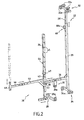
- la figure 1 est une vue en perspective d'un échafaudage selon l'invention comportant deux ensembles de fixation montés sur deux fenêtres ménagées dans un mur vertical ;
- la figure 2 est une vue en perspective d'un élément de fixation d'un échafaudage conforme à l'invention ;
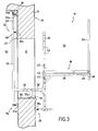
- la figure 3 est une vue latérale en coupe d'une baie de fenêtre sur laquelle est montée un élément de fixation d'un échafaudage selon l'invention, la cornière étant disposée de telle sorte que sa branche horizontale est située au dessus de la branche verticale ; et
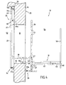
- la figure 4 est une vue latérale en coupe d'une baie de fenêtre sur laquelle est montée un élément de fixation d'un échafaudage selon l'invention, la cornière étant disposée de telle sorte que sa branche horizontale est située en dessous de la branche verticale.
- Figure 1 is a perspective view of a scaffold according to the invention comprising two fixing assemblies mounted on two windows formed in a vertical wall;
- Figure 2 is a perspective view of a fastening element of a scaffold according to the invention;
- FIG. 3 is a sectional side view of a window bay on which is mounted a scaffolding fastening element according to the invention, the angle being arranged in such a way that its horizontal branch is located above the branch. vertical; and
- FIG. 4 is a sectional side view of a window bay on which is mounted a scaffolding fastening element according to the invention, the angle being arranged in such a way that its horizontal branch is located below the branch; vertical.
En se référant à la figure 1, on va maintenant décrire plus en détail un mode préféré de réalisation d'un échafaudage conforme à la présente invention.Referring to Figure 1, there will now be described in more detail a preferred embodiment of a scaffold according to the present invention.
L'échafaudage 10 représenté ici est conçu pour coopérer avec deux baies de fenêtres 12, 14 ménagées sensiblement à la même hauteur dans un mur extérieur 16 d'une maison.The
Toutefois, on ne sortirait pas de l'invention si l'échafaudage 10 coopérait avec une unique ouverture, ou bien avec une pluralité d'ouvertures disposées sensiblement à même hauteur.However, it would not go beyond the invention if the
Comme on le voit sur la figure 1, les deux baies de fenêtres 12, 14 ont des dimensions différentes et leurs bords inférieurs ne sont pas disposés dans un même plan horizontal. Cette représentation permet de bien montrer l'adaptabilité de l'échafaudage selon l'invention à tout type de baies de fenêtres. En effet, l'échafaudage selon l'invention permet avantageusement de coopérer avec plusieurs ouvertures disposées sensiblement mais non exactement à même hauteur.As seen in Figure 1, the two
L'échafaudage 10 soutien une plate-forme horizontale 18 qui s'étend le long du mur 16 dans un plan substantiellement orthogonal à la surface du mur sur une distance comprise entre les bords verticaux les plus éloignés des deux ouvertures 12,14 formant baies de fenêtre 12,14. The
Cette plate-forme 18 est destinée à soutenir un ou plusieurs utilisateurs 20. This
La plate-forme horizontale 18 est soutenue par deux ensembles de fixation 22,24 disposés substantiellement à chaque extrémité de ladite plate-forme et coopérant chacun avec une baie de fenêtre.The
Comme on le constate à l'aide de la figure 1, l'échafaudage 10 selon l'invention prend appui sur la face extérieure du mur 16 et, par conséquent, il n'est pas nécessaire que l'échafaudage 10 prenne appui sur le sol.As can be seen from FIG. 1, the
Plus précisément, chaque élément de fixation 22,24 est destiné à coopérer avec une baie de fenêtre de façon à être solidarisé avec le mur 16. More specifically, each
Comme on le décrira plus tard, chaque élément de fixation 22,24 est apte à prendre appui sur les faces extérieure 25 et intérieure 27 du mur 16. As will be described later, each
À l'aide de la figure 2, on va maintenant décrire plus en détail un élément de fixation 22,24. With the help of Figure 2, we will now describe in more detail a
Chaque élément de fixation 22,24 comprend une barre verticale extérieure 26 dont l'extrémité inférieure comporte des premiers moyens d'appui 28 comprenant de préférence une paire de tampons d'appui en caoutchouc 28a, chacun des tampons d'appui présentant de préférence la forme d'un disque épais formant une surface d'appui disposée dans un plan sensiblement vertical.Each
L'élément de fixation 22 comprend en outre une barre verticale intérieure 29 qui comporte des deuxièmes moyens d'appui 32 situés à son extrémité supérieure et des troisièmes moyens d'appui 34 situés à son extrémité inférieure.The
De manière préférentielle, la longueur de la barre verticale intérieure 29 peut être réglée grâce à un bras télescopique vertical 29', qui est solidarisable avec la barre verticale intérieure, dans laquelle il coulisse, par l'entremise d'une vis 60 de serrage.Preferably, the length of the inner
L'intérêt de ce réglage vertical sera décrit plus en détail ci-après.The interest of this vertical adjustment will be described in more detail below.
Les deuxièmes 32 moyens d'appui comportent une paire de tampons d'appui en caoutchouc 32a, chacun des tampons d'appui se présentant également de manière préférentielle sous la forme de disques épais formant des surfaces d'appui disposées dans un plan sensiblement vertical.The second support means 32 comprise a pair of
De manière préférentielle, les deuxièmes 32 moyens d'appui peuvent comporter une paire additionnelle de tampons d'appui en caoutchouc 33a, chacun des tampons d'appui se présentant de manière préférentielle sous la forme de disques épais formant des surfaces d'appui disposées dans un plan sensiblement horizontal.Preferably, the second support means 32 may comprise an additional pair of
Les troisièmes 34 moyens d'appui comportent une paire de tampons d'appui en caoutchouc 34a, chacun des tampons d'appui se présentant de manière préférentielle sous la forme de disques épais formant des surfaces d'appui disposées dans un plan sensiblement vertical.The third support means 34 comprise a pair of
De manière préférentielle, la vis de serrage 60 peut comporter à son extrémité un tampon d'appui 60a analogue à ceux décrits précédemment.Preferably, the clamping
Les tampons d'appui 28a,32a,34a des premiers, deuxièmes et troisièmes moyens d'appui et le tampon d'appui 60a associé à la vis de serrage 60, sont disposés de telle sorte que leurs surfaces d'appui respectives sont en vis-à-vis.The
Les barres verticales extérieure 26 et intérieure 29 sont reliées solidairement ensembles par l'intermédiaire des extrémités d'une barre horizontale transversale 36. The outer 26 and inner 29 vertical bars are integrally connected together via the ends of a transverse
Vu depuis les deuxièmes moyens d'appui 32, la barre horizontale 36 est fixée sensiblement de manière préférentielle aux deux tiers de la longueur de la barre verticale intérieure 29. Viewed from the second support means 32, the
De même, vu depuis les premiers moyens d'appui 28, la barre horizontale 36 est fixée sensiblement aux deux tiers de la longueur de la barre verticale extérieure 26. Similarly, seen from the first support means 28, the
Évidemment, ces positions de fixation sont données à titre d'exemple et ne constituent pas une limitation.Obviously, these attachment positions are given by way of example and do not constitute a limitation.
En outre, la longueur de la barre horizontale 36 peut être réglée, de préférence grâce à un bras télescopique 36' visible sur la figure 2, de manière à pouvoir adapter l'élément de fixation à la l'épaisseur du mur 16. In addition, the length of the
Pour des raisons explicitées ci-après, il est toutefois avantageux que les deuxièmes moyens d'appui 32 soient positionnés entre la barre horizontale 36 et les premiers moyens d'appui 28, comme cela est représenté sur la figure 2. For reasons explained hereinafter, however, it is advantageous for the second support means 32 to be positioned between the
La barre horizontale 36 présente préférentiellement mais non nécessairement des quatrièmes moyens d'appui 30 comprenant un tampon d'appui en caoutchouc 30a présentant la forme d'un disque épais formant une surface d'appui disposée dans un plan substantiellement horizontal dont la fonction sera explicitée ci-après.The
Chaque élément de fixation comporte en outre une cornière 38 fixée de manière réglable à la barre verticale extérieure 26. Each fastening element further comprises an
Cette cornière 38 comprend une branche horizontale 40 et une branche verticale 42 apte à coulisser verticalement dans un canal 44 formé dans la barre verticale extérieure 26. This
De manière préférentielle, la barre verticale extérieure 26 présente, dans un plan transversal, une section sensiblement en forme de « U ».Preferably, the outer
Comme on le voit sur la figure 2, la barre verticale extérieure 26 comporte une pluralité de perçages transversaux 45 disposés périodiquement sur sensiblement toute sa longueur. La branche verticale 42 de la cornière 38 comporte également une pluralité de perçages transversaux (non représentés ici) et la fixation de la barre verticale extérieure 26 avec la branche verticale 42 de la cornière 38 peut être réalisée avec des goupilles 47 traversant transversalement ladite barre verticale 26 et ladite branche 42 à travers lesdits perçages.As seen in Figure 2, the outer
En se référant à la figure 1, on comprend que la branche horizontale 40 de la cornière 38 est destinée à soutenir la plate-forme 18. Plus précisément, ce sont les deux branches horizontales 40,40' des deux cornières 38,38' des deux ensembles de fixations 22,24 qui soutiennent la plate-forme 18. Referring to Figure 1, it is understood that the
La branche horizontale 40 de la cornière 38 est avantageusement dépliable dans le sens de sa longueur de manière à s'adapter à la largeur de la plate-forme 18. The
De préférence, la branche horizontale 40 comprend un bras télescopique 46 qui est muni à son extrémité d'un porte tige vertical 48, destinée à maintenir un des deux bras horizontaux d'une barrière 50 formant garde-fous, représentée sur la figure 1. Preferably, the
À l'aide de la figure 3, on va à présent décrire comment un élément de fixation 22 prend appui sur le mur 16. With the help of Figure 3, we will now describe how a
La figure 3 représente une vue latérale en coupe de la baie de fenêtre sur laquelle est monté un élément de fixation 22,24. Figure 3 shows a sectional side view of the window bay on which is mounted a
Le mur 16 de la maison représentée sur cette figure délimite une zone intérieure 52 et une zone extérieure 54. The
La barre verticale extérieure 26 est disposée dans la zone extérieure 54, le tampon caoutchouc 28a des premiers moyens d'appui étant disposé en dessous de la baie de la fenêtre.The outer
La barre verticale intérieure 29 est disposée dans la zone intérieure 52, le tampon 32a des deuxièmes moyens d'appui 32 prenant appui au-dessus de la baie de la fenêtre et les tampons 34a des troisièmes moyens d'appui 34 prenant appui en dessous de la baie de fenêtre. On comprend donc que la barre verticale intérieure 29 présente préférentiellement une longueur sensiblement supérieure à la hauteur de la baie de fenêtre.The inner
Naturellement, l'élément de fixation 22 est disposé de manière que la barre horizontale 36 traverse la baie de fenêtre, et le tampon 30 des quatrièmes moyens d'appui est disposé de manière à prendre appui sur un bord inférieur 56 de la baie de fenêtre.Naturally, the fixing
À l'aide de la figure 3 et de la figure 1, on comprend que lorsqu'un ouvrier 20 est positionné sur la plate-forme 18, son poids crée un couple de rotation qui tend à faire pivoter en arrière l'élément de fixation 22,24 selon une direction qui s'éloigne du mur 16. With the help of Figure 3 and Figure 1, it is understood that when a
Autrement dit, en se référant à la figure 3, on comprend que le poids d'un ouvrier 20 a tendance à faire pivoter l'élément de fixation 22 dans le sens trigonométrique.In other words, referring to FIG. 3, it will be understood that the weight of a
L'ensemble formé par les tampons d'appui en caoutchouc 28a,32a des premiers et deuxièmes moyens d'appui 28,32 permet avantageusement d'empêcher que l'élément de fixation 22 ne pivote dans un sens trigonométrique.The assembly formed by the
En outre, l'ensemble formé par les tampons d'appui en caoutchouc 28a,34a des premiers et troisièmes moyens d'appui 28,34 permet avantageusement de serrer en étau la partie du mur qui se trouve sous la baie de fenêtre.In addition, the assembly formed by the
On comprend ainsi que les troisièmes moyens d'appui 34 ne sont pas systématiquement nécessaires, toutefois ils améliorent le blocage de l'échafaudage en offrant un appui supplémentaire et permet d'améliorer la sécurité de l'échafaudage.It is thus understood that the third support means 34 are not systematically necessary, however they improve the blocking of the scaffolding by providing additional support and improves the safety of the scaffolding.
Le tampon en caoutchouc 30a des quatrièmes moyens d'appui 30 permet quant à eux de bloquer verticalement l'élément de fixation 22 en prenant appui sur le bord inférieur de la baie de fenêtre.The
Comme on le constate en particulier sur la figure 2, on peut prévoir que les quatrièmes moyens d'appui 30 soient déplaçables horizontalement selon la direction de la barre horizontale transversale 36, de manière à pouvoir par exemple s'adapter à la forme du bord inférieur 56. As can be seen in particular in FIG. 2, provision can be made for the fourth support means 30 to be horizontally displaceable in the direction of the transverse
Toujours à l'aide de la figure 1, on comprend que le tampon d'appui 60a associé à la vis de serrage 60 est disposé de manière à être apte à prendre appui sur la face intérieure 27 du mur 16, au dessus de la baie de fenêtre 12. Still with reference to FIG. 1, it is understood that the
Lorsqu'ils sont présents, les tampons d'appui 33a situés à l'extrémité supérieure de la barre verticale intérieure 29 et disposés dans un plan horizontal, sont aptes à prendre appui sur un plafond 17. When they are present, the
On comprend donc que l'on améliore encore le blocage de l'élément de fixation et donc la sécurité de l'échafaudage.It is therefore understood that it further improves the locking of the fastener and thus the safety of the scaffolding.
De manière préférentielle, tous les moyens d'appui sont réglables verticalement et/ou horizontalement de manière à s'adapter à la forme des faces extérieure et intérieure du mur 16, ainsi qu'au bord inférieur de la baie de fenêtre.Preferably, all the support means are adjustable vertically and / or horizontally so as to adapt to the shape of the outer and inner faces of the
À l'aide des figures 3 et 4, on va maintenant décrire les deux orientations que peut prendre la branche horizontale 40. With the aid of FIGS. 3 and 4, we will now describe the two orientations that the
En effet, la cornière 38 peut être positionnée au moins de deux façons par rapport à la barre verticale extérieure de sorte que la branche horizontale 40 peut être disposée soit au-dessus soit en dessous de la branche verticale 44. Indeed, the
Sur la figure 3, la cornière est positionnée de telle sorte que la branche horizontale 40 est disposée au-dessus de la branche verticale 42. In FIG. 3, the angle is positioned in such a way that the
Et, sur la figure 4, la cornière est positionnée de telle sorte que la branche horizontale 40 est disposée en dessous de la branche verticale.And, in Figure 4, the angle is positioned so that the
Plus précisément, la cornière 38 est fixée à l'extrémité inférieure de la barre verticale extérieure 26 de telle sorte qu'il n'est plus possible de descendre la branche verticale 42 de la cornière 38. More specifically, the
En faisant tourner la cornière de 180° de sorte que la branche horizontale 40 soit positionnée en dessous de la branche verticale, et cela sans modifier la position en hauteur de la branche horizontale, il est possible d'amener la plate-forme 18 dans une position extrême basse, comme cela est représenté sur la figure 4, de sorte qu'un plan de la plate-forme 18 puisse être disposé en dessous d'un plan sensiblement horizontal passant par le bord inférieur 56, afin que l'utilisateur puisse accéder facilement à une zone située sous le bord inférieur 56. By rotating the angle of 180 ° so that the
On comprend qu'il est également possible d'amener la plate-forme 18 dans une position extrême haute, en disposant la branche verticale de la cornière 34 au plus haut de la barre verticale extérieure 26 tout en ayant la branche horizontale de la cornière disposée au-dessus de la branche verticale.It is understood that it is also possible to bring the
Claims (14)
Applications Claiming Priority (1)
| Application Number | Priority Date | Filing Date | Title |
|---|---|---|---|
| FR0501027A FR2881450B1 (en) | 2005-02-02 | 2005-02-02 | SCAFFOLDING OF WINDOWS |
Publications (2)
| Publication Number | Publication Date |
|---|---|
| EP1700975A1 true EP1700975A1 (en) | 2006-09-13 |
| EP1700975B1 EP1700975B1 (en) | 2009-04-01 |
Family
ID=35005755
Family Applications (1)
| Application Number | Title | Priority Date | Filing Date |
|---|---|---|---|
| EP06290190A Active EP1700975B1 (en) | 2005-02-02 | 2006-02-02 | Scaffold mountable in window opening |
Country Status (4)
| Country | Link |
|---|---|
| EP (1) | EP1700975B1 (en) |
| AT (1) | ATE427392T1 (en) |
| DE (1) | DE602006005969D1 (en) |
| FR (1) | FR2881450B1 (en) |
Cited By (2)
| Publication number | Priority date | Publication date | Assignee | Title |
|---|---|---|---|---|
| EP2246288A1 (en) | 2009-04-06 | 2010-11-03 | Ivar Ole Wik | Device for transporting goods, and use thereof |
| CN103790368A (en) * | 2012-10-29 | 2014-05-14 | 五冶集团上海有限公司 | Simple aerial work platform erection method |
Families Citing this family (4)
| Publication number | Priority date | Publication date | Assignee | Title |
|---|---|---|---|---|
| WO2008077202A1 (en) * | 2006-12-27 | 2008-07-03 | Zoran Dujakovic | Mobile scaffold for working at heights |
| KR20180079418A (en) | 2015-11-02 | 2018-07-10 | 존 프레스톤 | Loading platform |
| US11939782B2 (en) | 2020-01-21 | 2024-03-26 | Aaa Royal Construction Llc | Wall-mountable perch |
| CN113789945B (en) * | 2021-07-19 | 2023-02-03 | 中国建筑第二工程局有限公司 | Sliding type safety operation frame for out-window construction and construction method thereof |
Citations (7)
| Publication number | Priority date | Publication date | Assignee | Title |
|---|---|---|---|---|
| BE386576A (en) * | ||||
| FR959745A (en) | 1950-04-04 | |||
| US4079813A (en) | 1976-06-29 | 1978-03-21 | The Raymond Lee Organization, Inc. | Step-out window washer box |
| GB2141771A (en) * | 1983-05-11 | 1985-01-03 | Michael Percy Cowles | Builder's cradle |
| FR2660955A1 (en) * | 1990-04-12 | 1991-10-18 | Step Arcadia | Platform for working overhead |
| US5203426A (en) * | 1992-02-11 | 1993-04-20 | Sydnor Eugene E | Portable window perch assembly |
| US20030127283A1 (en) * | 2001-12-26 | 2003-07-10 | Clifton Deal | Adjustable scaffold and walkboard ladder holder |
-
2005
- 2005-02-02 FR FR0501027A patent/FR2881450B1/en not_active Expired - Fee Related
-
2006
- 2006-02-02 AT AT06290190T patent/ATE427392T1/en not_active IP Right Cessation
- 2006-02-02 EP EP06290190A patent/EP1700975B1/en active Active
- 2006-02-02 DE DE602006005969T patent/DE602006005969D1/en active Active
Patent Citations (7)
| Publication number | Priority date | Publication date | Assignee | Title |
|---|---|---|---|---|
| BE386576A (en) * | ||||
| FR959745A (en) | 1950-04-04 | |||
| US4079813A (en) | 1976-06-29 | 1978-03-21 | The Raymond Lee Organization, Inc. | Step-out window washer box |
| GB2141771A (en) * | 1983-05-11 | 1985-01-03 | Michael Percy Cowles | Builder's cradle |
| FR2660955A1 (en) * | 1990-04-12 | 1991-10-18 | Step Arcadia | Platform for working overhead |
| US5203426A (en) * | 1992-02-11 | 1993-04-20 | Sydnor Eugene E | Portable window perch assembly |
| US20030127283A1 (en) * | 2001-12-26 | 2003-07-10 | Clifton Deal | Adjustable scaffold and walkboard ladder holder |
Cited By (3)
| Publication number | Priority date | Publication date | Assignee | Title |
|---|---|---|---|---|
| EP2246288A1 (en) | 2009-04-06 | 2010-11-03 | Ivar Ole Wik | Device for transporting goods, and use thereof |
| CN103790368A (en) * | 2012-10-29 | 2014-05-14 | 五冶集团上海有限公司 | Simple aerial work platform erection method |
| CN103790368B (en) * | 2012-10-29 | 2016-06-01 | 五冶集团上海有限公司 | Simple platform for work high above ground erection method |
Also Published As
| Publication number | Publication date |
|---|---|
| DE602006005969D1 (en) | 2009-05-14 |
| FR2881450A1 (en) | 2006-08-04 |
| ATE427392T1 (en) | 2009-04-15 |
| FR2881450B1 (en) | 2007-05-11 |
| EP1700975B1 (en) | 2009-04-01 |
Similar Documents
| Publication | Publication Date | Title |
|---|---|---|
| EP1700975B1 (en) | Scaffold mountable in window opening | |
| EP2393402B1 (en) | Drive carriage for a sliding curtain | |
| EP2712382A1 (en) | Framework for walls | |
| FR3047260B1 (en) | BODY WELDER | |
| FR3074512A1 (en) | DEVICE FOR ASSISTING THE CONSTRUCTION OF A WALL FROM PREFABRICATED STRUCTURAL ELEMENTS, PERMITTING THE APPROACH, ADJUSTMENT AND POSITIONING OF THE PREFABRICATED ELEMENTS | |
| FR2624173A1 (en) | Climbing platform-scaffolding forming an independent unit | |
| FR2883018A1 (en) | Functional block for telescopic type swimming pool shelter, has body with guiding units to guide one covering section relative to other covering section in translation direction of sections, between covering and opening positions of shelter | |
| EP0774032B1 (en) | Adjustable staircase | |
| EP3141152B1 (en) | A removable table with a reduced bulk, in particular for a railway vehicle | |
| FR2976791A1 (en) | Retractable barrier for maintaining patient lying on healthcare bed, has locking devices respectively mounted on rotational axes of posts with respect to supports, where locking devices lock respective posts in service position | |
| EP1679408A2 (en) | Articulation device for foldable platform as well as platform with such a device | |
| EP1052344B1 (en) | Kit for mounting a straight stairway and mounting method using it | |
| EP0734665B1 (en) | Bedding unit, with superimposed tiltable bases, equipped with floor support means | |
| EP3392430A1 (en) | Inspection hatch | |
| EP0282385B1 (en) | Device for anchoring at rafters for roof works | |
| FR2681623A1 (en) | Protection device for working on roofs | |
| FR2976011A1 (en) | MODULAR PROTECTION DEVICE | |
| FR2862679A1 (en) | Foldable ladder for use with swiveling trap door, has three parts including posts and stairs and foldable on each other through articulation unit, where widths of stairs are equal to or greater than widths of posts | |
| EP1643055A1 (en) | Adjustable mounting device for a handrail | |
| EP0156663A1 (en) | Device preventing a ski from slipping back | |
| FR3139157A1 (en) | Stopper, suspension system and concealment device comprising at least one such stopper | |
| FR2776005A1 (en) | Safety barrier for building window | |
| FR2665098A1 (en) | Suspended work surface | |
| FR2783141A1 (en) | SIDE TABLE | |
| WO2019201760A1 (en) | Retractable seat for a perched position |
Legal Events
| Date | Code | Title | Description |
|---|---|---|---|
| PUAI | Public reference made under article 153(3) epc to a published international application that has entered the european phase |
Free format text: ORIGINAL CODE: 0009012 |
|
| AK | Designated contracting states |
Kind code of ref document: A1 Designated state(s): AT BE BG CH CY CZ DE DK EE ES FI FR GB GR HU IE IS IT LI LT LU LV MC NL PL PT RO SE SI SK TR |
|
| AX | Request for extension of the european patent |
Extension state: AL BA HR MK YU |
|
| 17P | Request for examination filed |
Effective date: 20061130 |
|
| 17Q | First examination report despatched |
Effective date: 20070116 |
|
| AKX | Designation fees paid |
Designated state(s): AT BE BG CH CY CZ DE DK EE ES FI FR GB GR HU IE IS IT LI LT LU LV MC NL PL PT RO SE SI SK TR |
|
| GRAP | Despatch of communication of intention to grant a patent |
Free format text: ORIGINAL CODE: EPIDOSNIGR1 |
|
| GRAS | Grant fee paid |
Free format text: ORIGINAL CODE: EPIDOSNIGR3 |
|
| GRAA | (expected) grant |
Free format text: ORIGINAL CODE: 0009210 |
|
| AK | Designated contracting states |
Kind code of ref document: B1 Designated state(s): AT BE BG CH CY CZ DE DK EE ES FI FR GB GR HU IE IS IT LI LT LU LV MC NL PL PT RO SE SI SK TR |
|
| REG | Reference to a national code |
Ref country code: GB Ref legal event code: FG4D Free format text: NOT ENGLISH |
|
| REG | Reference to a national code |
Ref country code: CH Ref legal event code: EP |
|
| REG | Reference to a national code |
Ref country code: IE Ref legal event code: FG4D Free format text: LANGUAGE OF EP DOCUMENT: FRENCH |
|
| REF | Corresponds to: |
Ref document number: 602006005969 Country of ref document: DE Date of ref document: 20090514 Kind code of ref document: P |
|
| PG25 | Lapsed in a contracting state [announced via postgrant information from national office to epo] |
Ref country code: SI Free format text: LAPSE BECAUSE OF FAILURE TO SUBMIT A TRANSLATION OF THE DESCRIPTION OR TO PAY THE FEE WITHIN THE PRESCRIBED TIME-LIMIT Effective date: 20090401 |
|
| NLV1 | Nl: lapsed or annulled due to failure to fulfill the requirements of art. 29p and 29m of the patents act | ||
| REG | Reference to a national code |
Ref country code: IE Ref legal event code: FD4D |
|
| PG25 | Lapsed in a contracting state [announced via postgrant information from national office to epo] |
Ref country code: PT Free format text: LAPSE BECAUSE OF FAILURE TO SUBMIT A TRANSLATION OF THE DESCRIPTION OR TO PAY THE FEE WITHIN THE PRESCRIBED TIME-LIMIT Effective date: 20090902 Ref country code: EE Free format text: LAPSE BECAUSE OF FAILURE TO SUBMIT A TRANSLATION OF THE DESCRIPTION OR TO PAY THE FEE WITHIN THE PRESCRIBED TIME-LIMIT Effective date: 20090401 Ref country code: LT Free format text: LAPSE BECAUSE OF FAILURE TO SUBMIT A TRANSLATION OF THE DESCRIPTION OR TO PAY THE FEE WITHIN THE PRESCRIBED TIME-LIMIT Effective date: 20090401 Ref country code: ES Free format text: LAPSE BECAUSE OF FAILURE TO SUBMIT A TRANSLATION OF THE DESCRIPTION OR TO PAY THE FEE WITHIN THE PRESCRIBED TIME-LIMIT Effective date: 20090712 Ref country code: FI Free format text: LAPSE BECAUSE OF FAILURE TO SUBMIT A TRANSLATION OF THE DESCRIPTION OR TO PAY THE FEE WITHIN THE PRESCRIBED TIME-LIMIT Effective date: 20090401 Ref country code: AT Free format text: LAPSE BECAUSE OF FAILURE TO SUBMIT A TRANSLATION OF THE DESCRIPTION OR TO PAY THE FEE WITHIN THE PRESCRIBED TIME-LIMIT Effective date: 20090401 |
|
| PG25 | Lapsed in a contracting state [announced via postgrant information from national office to epo] |
Ref country code: NL Free format text: LAPSE BECAUSE OF FAILURE TO SUBMIT A TRANSLATION OF THE DESCRIPTION OR TO PAY THE FEE WITHIN THE PRESCRIBED TIME-LIMIT Effective date: 20090401 Ref country code: IS Free format text: LAPSE BECAUSE OF FAILURE TO SUBMIT A TRANSLATION OF THE DESCRIPTION OR TO PAY THE FEE WITHIN THE PRESCRIBED TIME-LIMIT Effective date: 20090801 Ref country code: LV Free format text: LAPSE BECAUSE OF FAILURE TO SUBMIT A TRANSLATION OF THE DESCRIPTION OR TO PAY THE FEE WITHIN THE PRESCRIBED TIME-LIMIT Effective date: 20090401 Ref country code: PL Free format text: LAPSE BECAUSE OF FAILURE TO SUBMIT A TRANSLATION OF THE DESCRIPTION OR TO PAY THE FEE WITHIN THE PRESCRIBED TIME-LIMIT Effective date: 20090401 Ref country code: SE Free format text: LAPSE BECAUSE OF FAILURE TO SUBMIT A TRANSLATION OF THE DESCRIPTION OR TO PAY THE FEE WITHIN THE PRESCRIBED TIME-LIMIT Effective date: 20090701 |
|
| PG25 | Lapsed in a contracting state [announced via postgrant information from national office to epo] |
Ref country code: CZ Free format text: LAPSE BECAUSE OF FAILURE TO SUBMIT A TRANSLATION OF THE DESCRIPTION OR TO PAY THE FEE WITHIN THE PRESCRIBED TIME-LIMIT Effective date: 20090401 Ref country code: RO Free format text: LAPSE BECAUSE OF FAILURE TO SUBMIT A TRANSLATION OF THE DESCRIPTION OR TO PAY THE FEE WITHIN THE PRESCRIBED TIME-LIMIT Effective date: 20090401 Ref country code: IE Free format text: LAPSE BECAUSE OF FAILURE TO SUBMIT A TRANSLATION OF THE DESCRIPTION OR TO PAY THE FEE WITHIN THE PRESCRIBED TIME-LIMIT Effective date: 20090401 Ref country code: DK Free format text: LAPSE BECAUSE OF FAILURE TO SUBMIT A TRANSLATION OF THE DESCRIPTION OR TO PAY THE FEE WITHIN THE PRESCRIBED TIME-LIMIT Effective date: 20090401 |
|
| PLBE | No opposition filed within time limit |
Free format text: ORIGINAL CODE: 0009261 |
|
| STAA | Information on the status of an ep patent application or granted ep patent |
Free format text: STATUS: NO OPPOSITION FILED WITHIN TIME LIMIT |
|
| PG25 | Lapsed in a contracting state [announced via postgrant information from national office to epo] |
Ref country code: SK Free format text: LAPSE BECAUSE OF FAILURE TO SUBMIT A TRANSLATION OF THE DESCRIPTION OR TO PAY THE FEE WITHIN THE PRESCRIBED TIME-LIMIT Effective date: 20090401 |
|
| 26N | No opposition filed |
Effective date: 20100105 |
|
| PG25 | Lapsed in a contracting state [announced via postgrant information from national office to epo] |
Ref country code: BG Free format text: LAPSE BECAUSE OF FAILURE TO SUBMIT A TRANSLATION OF THE DESCRIPTION OR TO PAY THE FEE WITHIN THE PRESCRIBED TIME-LIMIT Effective date: 20090701 |
|
| BERE | Be: lapsed |
Owner name: THEVENIN SA Effective date: 20100228 |
|
| REG | Reference to a national code |
Ref country code: CH Ref legal event code: PL |
|
| PG25 | Lapsed in a contracting state [announced via postgrant information from national office to epo] |
Ref country code: MC Free format text: LAPSE BECAUSE OF NON-PAYMENT OF DUE FEES Effective date: 20100301 Ref country code: CH Free format text: LAPSE BECAUSE OF NON-PAYMENT OF DUE FEES Effective date: 20100228 Ref country code: GR Free format text: LAPSE BECAUSE OF FAILURE TO SUBMIT A TRANSLATION OF THE DESCRIPTION OR TO PAY THE FEE WITHIN THE PRESCRIBED TIME-LIMIT Effective date: 20090702 Ref country code: LI Free format text: LAPSE BECAUSE OF NON-PAYMENT OF DUE FEES Effective date: 20100228 |
|
| PG25 | Lapsed in a contracting state [announced via postgrant information from national office to epo] |
Ref country code: BE Free format text: LAPSE BECAUSE OF NON-PAYMENT OF DUE FEES Effective date: 20100228 |
|
| PG25 | Lapsed in a contracting state [announced via postgrant information from national office to epo] |
Ref country code: IT Free format text: LAPSE BECAUSE OF FAILURE TO SUBMIT A TRANSLATION OF THE DESCRIPTION OR TO PAY THE FEE WITHIN THE PRESCRIBED TIME-LIMIT Effective date: 20090401 |
|
| PG25 | Lapsed in a contracting state [announced via postgrant information from national office to epo] |
Ref country code: CY Free format text: LAPSE BECAUSE OF FAILURE TO SUBMIT A TRANSLATION OF THE DESCRIPTION OR TO PAY THE FEE WITHIN THE PRESCRIBED TIME-LIMIT Effective date: 20090401 |
|
| PG25 | Lapsed in a contracting state [announced via postgrant information from national office to epo] |
Ref country code: LU Free format text: LAPSE BECAUSE OF NON-PAYMENT OF DUE FEES Effective date: 20100202 Ref country code: HU Free format text: LAPSE BECAUSE OF FAILURE TO SUBMIT A TRANSLATION OF THE DESCRIPTION OR TO PAY THE FEE WITHIN THE PRESCRIBED TIME-LIMIT Effective date: 20091002 |
|
| PG25 | Lapsed in a contracting state [announced via postgrant information from national office to epo] |
Ref country code: TR Free format text: LAPSE BECAUSE OF FAILURE TO SUBMIT A TRANSLATION OF THE DESCRIPTION OR TO PAY THE FEE WITHIN THE PRESCRIBED TIME-LIMIT Effective date: 20090401 |
|
| REG | Reference to a national code |
Ref country code: FR Ref legal event code: PLFP Year of fee payment: 11 |
|
| REG | Reference to a national code |
Ref country code: FR Ref legal event code: PLFP Year of fee payment: 12 |
|
| REG | Reference to a national code |
Ref country code: FR Ref legal event code: PLFP Year of fee payment: 13 |
|
| PGFP | Annual fee paid to national office [announced via postgrant information from national office to epo] |
Ref country code: DE Payment date: 20240213 Year of fee payment: 19 Ref country code: GB Payment date: 20240221 Year of fee payment: 19 |
|
| PGFP | Annual fee paid to national office [announced via postgrant information from national office to epo] |
Ref country code: FR Payment date: 20240202 Year of fee payment: 19 |