EP1700691B2 - Druckplattenherstellungsgerät - Google Patents
Druckplattenherstellungsgerät Download PDFInfo
- Publication number
- EP1700691B2 EP1700691B2 EP06003518A EP06003518A EP1700691B2 EP 1700691 B2 EP1700691 B2 EP 1700691B2 EP 06003518 A EP06003518 A EP 06003518A EP 06003518 A EP06003518 A EP 06003518A EP 1700691 B2 EP1700691 B2 EP 1700691B2
- Authority
- EP
- European Patent Office
- Prior art keywords
- engraving
- laser
- laser beam
- coarse
- precision
- Prior art date
- Legal status (The legal status is an assumption and is not a legal conclusion. Google has not performed a legal analysis and makes no representation as to the accuracy of the status listed.)
- Not-in-force
Links
Images


Classifications
-
- B—PERFORMING OPERATIONS; TRANSPORTING
- B41—PRINTING; LINING MACHINES; TYPEWRITERS; STAMPS
- B41C—PROCESSES FOR THE MANUFACTURE OR REPRODUCTION OF PRINTING SURFACES
- B41C1/00—Forme preparation
- B41C1/02—Engraving; Heads therefor
- B41C1/04—Engraving; Heads therefor using heads controlled by an electric information signal
- B41C1/05—Heat-generating engraving heads, e.g. laser beam, electron beam
Definitions
- Conventional platemaking apparatus of the type noted above include a laser engraving machine as described in United States Patent No. 5,327,167 , for example.
- This laser engraving machine makes letterpress printing plates by scanning a recording material with a laser beam emitted from a laser source to engrave the surface of the recording material.
- the machine includes a modulator for modulating the laser beam emitted from the laser source, a recording drum rotatable with the recording material mounted peripherally thereof, and a recording head movable in a direction parallel to the axis of the recording drum for irradiating the recording material mounted peripherally of the recording drum with the laser beam emitted from the laser source.
- the main scanning speed of the laser beam i.e. the rotating speed of the recording drum
- the main scanning speed of the laser beam is set to a value for obtaining a required maximum engraving depth, based on the power of the laser source and the sensitivity of the recording material. Areas shallower than the maximum engraving depth are engraved by reducing the power of the laser beam emitted to the recording material. A relatively large amount of energy is required for engraving the recording material with a laser beam. Thus, there is a drawback of consuming a relatively long time in the platemaking process.
- Applicant herein has proposed a platemaking apparatus for engraving a recording material by irradiating the recording material at a first pixel pitch with a laser beam having a first beam diameter, and thereafter irradiating the recording material at a second pixel pitch different from the first pixel pitch with a laser beam having a second beam diameter different from the first beam diameter ( Japanese Patent Applications Nos. 2004-286175 and 2004-357586 ).
- the platemaking time may be shortened by using the laser beams efficiently.
- the printing block manufacturing method described in Japanese Patent No. 3556204 noted above can create relief efficiently by emitting a plurality of laser beams simultaneously to a recording material. However, it is difficult to obtain precise engraving results since the laser beams are moved at a fixed pixel pitch.
- a recording material is engraved by irradiating the recording material at a first pixel pitch with a laser beam having a first beam diameter, and thereafter irradiating the recording material at a second pixel pitch different from the first pixel pitch with a laser beam having a second beam diameter different from the first beam diameter, a precise engraving may be carried out efficiently, but the engraving requires two steps for its completion. Thus, an engraving process of enhanced efficiency is desired.
- a platemaking apparatus comprising a first laser source for irradiating the recording material at a first pixel pitch and a second laser source for irradiating the recording material at a second pixel pitch is known from DE 101 16 672 A1 .
- a platemaking apparatus in which the motion of a laser beam along the axis of a recording drum superimposed by a fast to and from motion of the laser beam along the axis of the recording drum is known from DE 43 13 111 A1 .
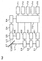
- Fig. 1 is a view showing an outline of a laser engraving machine which is a platemaking apparatus.
- Fig. 2 is a block diagram showing a principal portion of the apparatus.
- the laser engraving machine includes a recording drum 11 for supporting, as mounted peripherally thereof, a flexo direct photosensitive material (hereinafter called "flexo sensitive material") 10 serving as a recording material for a letterpress plate, and a recording head 20 movable in a direction parallel to the axis of the recording drum 11.
- flexo sensitive material a flexo direct photosensitive material
- the recording head 20 includes a first laser source 21 for emitting a precision engraving beam L1 as a first laser beam, an AOM (acoustooptic modulator) 22 acting as a first modulating device for modulating the precision engraving beam L1, an AOD (acoustooptic deflector) 23 for causing the precision engraving beam L1 modulated by the AOM 22 to scan axially of the recording drum 11, a second laser source 24 for emitting a coarse engraving beam L2 as a second laser beam, an AOM 25 acting as a second modulating device for modulating the coarse engraving beam L2, a beam synthesizer 27 for synthesizing the precision engraving beam L1 and coarse engraving beam L2, and an optic 26 for condensing the precision engraving beam L1 and coarse engraving beam L2 synthesized by the beam synthesizer 27 on the flexo sensitive material 10.
- the AOM 22 and AOD 23 may be integrated into a single device.
- the recording head 20 is guided by a guide device, not shown, to move relative to the recording drum 11 in the direction parallel to the axis of the recording drum 11.
- the recording head 20 is driven by a ball screw, not shown, rotatable by a moving motor, not shown, to reciprocate in the direction parallel to the axis of the recording drum 11.
- the moving motor is rotatable on a rotating speed command from a controller 70.
- a moving speed and positions of the recording head 20 moved by the moving motor are measured by an encoder, not shown, connected to the moving motor and transmitting resulting information to the controller 70.
- the first laser source 21 employed in this embodiment emits a beam having an optimal beam diameter as the precision engraving beam L1.
- the second laser source 24 emits a beam having an optimal beam diameter as the coarse engraving beam L2.
- beam expanders may be used to change the diameters of the laser beams emitted from the first and second laser sources to have optimal values.
- the beam synthesizer 27 may be in the form of a dichroic mirror using a difference in wavelength between the first laser source 21 and second laser light source 24, or a polarization beam splitter using a difference in polarization direction between the first laser source 21 and second laser source 24. Where the laser beam output leaves a margin, a half mirror or the like may be used as the beam synthesizer 27.
- the recording drum 11 shown in Fig. 1 is connected to a rotary motor 72 shown in Fig. 2 , to be rotatable about the axis thereof.
- the rotary motor 72 is rotatable on a rotating speed command from the controller 70.
- a rotating speed of the rotary motor 72 and angular positions of the recording drum 11 rotated by the rotary motor 72 are measured by an encoder 73 which transmits resulting information to the controller 70.
- the recording head 20 shown in Fig. 1 is guided by a guide device, not shown, to move relative to the recording drum 11 in the direction parallel to the axis of the recording drum 11.
- the recording head 20 is driven by a ball screw, not shown, rotatable by a moving motor 74 shown in Fig. 2 , to reciprocate in the direction parallel to the axis of the recording drum 11.
- the moving motor 74 is rotatable on a rotating speed command from the controller 70.
- a rotating speed of the moving motor 74 and positions of the recording head 20 moved by the moving motor 74 are measured by an encoder 75 which transmits resulting information to the controller 70.
- the first laser source 21 is connected to the controller 70 through a laser driver circuit 61.
- the AOM 22 is connected to the controller 70 through an AOM driver 62.
- the AOD 23 is connected to the controller 70 through an AOD driver circuit 63.
- the second laser source 24 is connected to the controller 70 through a laser driver circuit 64.
- the AOM 25 is connected to the controller 70 through an AOM driver 66.
- the first laser source 21 may be in the form of a YAG laser or fiber laser which emits near-infrared light. Where such a laser source is used as the first laser source 21, the laser beam has a wavelength of about 1 ⁇ m. This enables a very small final spot diameter of the laser beam in time of engraving. Great energy is not required for precision engraving that engraves to the maximum depth dp.
- the first laser source 21 need not have high power, and can therefore be inexpensive.
- Figs. 3A, 3B and 3C are explanatory views schematically showing a shape of the surface of the flexo sensitive material 10 engraved by using this laser engraving machine.
- Fig. 3A is a plan view of seven reliefs formed in a primary scanning direction on the flexo sensitive material 10.
- Fig. 3B is a sectional view of the reliefs. For facility of description, these figures show seven reliefs having dot percentages at 0%, 1%, 1%, 2%, 2%, 0% and 0% in order from left to right.
- the precision engraving beam L1 having a small diameter is used in the precision engraving.
- the precision engraving beam L1 irradiates the flexo sensitive material 10 at the precision engraving pixel pitch pp to engrave the flexo sensitive material 10 to the maximum depth dp from the surface.
- the coarse engraving is performed simultaneously with the precision engraving.
- the coarse engraving beam L2 having a large diameter is used in the coarse engraving.
- the coarse engraving beam L2 irradiates the flexo sensitive material 10 at the coarse engraving pixel pitch pc to engrave the flexo sensitive material 10 from the maximum depth dp to the relief depth d. Since the areas engraved in the precision engraving are engraved again in the coarse engraving, the engraving depth d from the surface of flexo sensitive material 10 resulting from the coarse engraving is greater than the engraving depth dp by the precision engraving.
- This coarse engraving is carried out to engrave portions of the flexo sensitive material 10 that have no direct influence on the shape of halftone dots. It is therefore possible to employ the large coarse engraving pixel pitch pc. This applies also to the case where the precision engraving and coarse engraving are taken in a reversed order.
- dp 2 1 / 2.
- FIGs. 5 and 6 are explanatory views showing signals used for causing scanning action of the precision engraving beam L1 and coarse engraving beam L2.
- Fig. 6 is an enlarged view showing a portion of Fig. 5 .
- the first modulating signal shown in these drawings is a signal for causing the AOM 25 to modulate the coarse engraving beam L2 for the coarse engraving.
- the first modulating signal turns on/off and changes the intensity of the coarse engraving beam L2.
- the second modulating signal is a signal for causing the AOM 22 to modulate the precision engraving beam L1.
- the second modulating signal turns on/off and changes the intensity of the precision engraving beam L1.
- the precision engraving beam L1 with rotation of the recording drum 11, performs engraving at the precision engraving pixel pitch pp during a scan in the primary scanning direction s1, and with the deflection by the AOD 23, performs engraving at the precision engraving pixel pitch pp during a scan in the secondary scanning direction s2 on the flexo sensitive material 10 within the coarse engraving pixel pitch pc.
- each of the precision engraving beam L1 and coarse engraving beam L2 can perform engraving at the required pixel pitch, thereby engraving a precise image at high speed.
- Fig. 7 is a flow chart showing the platemaking process.
- step S3 the maximum depth dp for the precision engraving and maximum depth dc for the coarse engraving are calculated. This operation is performed using equation (1) noted above.
- This resolution is selected from 1200dpi, 2400dpi and 4000dpi, for example.
- the precision engraving pixel pitch pp is determined from the resolution specified (step S5).
- the precision engraving beam L1 has a beam spot size adjusted so that the precision engraving pixel pitch pp and the width in the secondary scanning direction of the precision engraving beam L1 are substantially in agreement.
- the coarse engraving pixel pitch pc also is determined (step S6). This coarse engraving pixel pitch pc corresponds to the dot pitch w as noted hereinbefore.
- step S7 scan velocities for the engraving are determined.
- a scan velocity may be determined for each engraving process based on the engraving sensitivity variable with the diameter of the laser beam, the pixel pitch for each engraving process, the engraving depth according to the shape of relief engraved in each engraving process, and given laser beam power.
- the precision engraving process and coarse engraving process are performed simultaneously, and the scans by the precision engraving beam L1 and the scan by the coarse engraving beam L2 are synchronized.
- a laser beam power ratio is determined first for enabling a synchronized scan by these laser beams.
- power of the precision engraving beam is determined from the laser beam power ratio, with the power of the coarse engraving beam serving as a given condition.
- a scan velocity v1 along the secondary scanning direction s2 of the precision engraving beam L1 is calculated by applying the scan velocity v2 along the primary scanning direction s1 of the coarse engraving beam L2 to the above-noted scan velocity ratio.
- Fig. 8 is a flow chart showing details of steps included in step S7 of Fig. 7 .
- engraving sensitivity sp corresponding to the diameter of the precision engraving beam L1 is calculated (step S 7-1).
- Engraving sensitivity sp is a value resulting from the division of energy E of the laser beam by a volume V to be engraved by the laser beam.
- the energy E of the laser beam is a value resulting from the multiplication of the power of the laser source 21 by irradiation time.
- the engraving sensitivity in time of engraving the flexo sensitive material 10 is variable with the beam diameter.
- a table of degrees of engraving sensitivity matched against different diameters of the laser beam, or a formula for deriving degrees of engraving sensitivity from diameters of the laser beam is prepared beforehand by experiment.
- Engraving sensitivity sp is obtained by applying a diameter of the precision engraving beam L1 to this table or formula.
- Engraving sensitivity sc corresponding to a diameter of the coarse engraving beam L2 is obtained similarly (step S7-2).
- a flexo sensitive material volume vp to be engraved when engraving a rectangular area, which is the square of the coarse engraving pixel pitch pc, to the maximum depth dp of the precision engraving, is calculated (step S7-3).
- the rectangular area, or the square of the coarse engraving pixel pitch pc, is used as a reference area for determining a laser beam power ratio and a scan velocity ratio.
- Fig. 9 is a perspective view schematically showing an engraving state. As seen from Fig. 9 , the flexo sensitive material volume vp engraved by the precision engraving beam L1 is pc*pc*dp.
- a flexo sensitive material volume vc to be engraved when engraving a rectangular area, which is the square of the coarse engraving pixel pitch pc, to the maximum depth dc of the coarse engraving, is calculated (step S7-4).
- the flexo sensitive material volume vc is pc*pc*(d-dp).
- step S7-5 an amount of energy needed to engrave, with the precision engraving beam L1
- the flexo sensitive material 10 corresponding to the flexo sensitive material volume vp obtained in step S7-3 is calculated (step S7-5). This is equal to a value resulting from the multiplication of the flexo sensitive material volume vp by the engraving sensitivity sp in time of precision engraving.
- step S7-6 An amount of energy needed to engrave, with the coarse engraving beam L2, the flexo sensitive material 10 corresponding to the flexo sensitive material volume vc obtained in step S7-4 is calculated similarly (step S7-6). This is equal to a value resulting from the multiplication of the flexo sensitive material volume vc by the engraving sensitivity sc in time of coarse engraving.
- E1 is an amount of energy of the precision engraving beam L1
- E2 is an amount of energy of the coarse engraving beam 12
- PW1 is the power of the precision engraving beam L1
- PW2 is the power of the coarse engraving beam L2
- t1 is a time taken to scan the reference area
- t2 is a time taken to scan the reference area.
- the precision engraving and coarse engraving are performed synchronously.
- the time t1 taken for the precision engraving beam L1 to scan the reference area is equal to the time t2 taken for the coarse engraving beam L2 to scan the reference area.
- the sum of the power PW1 of the precision engraving beam L1 and the power PW2 of the coarse engraving beam L2 is considered overall laser power pw.
- the power PW2 of the coarse engraving beam L2 is expressed by equation (7).
- PW ⁇ 2 pw * vc * sc / vp * sp + vc * sc
- PW ⁇ 1 pc ⁇ pw ⁇ 4 ⁇ dt ⁇ ⁇ + 4 ⁇ pp ⁇ ⁇ + 2 ⁇ dt ⁇ ⁇ + 2 ⁇ pd - 2 ⁇ wt ⁇ 2 ⁇ ⁇ + pp ⁇ ⁇ ⁇ Tan ⁇ ⁇ ⁇ 180 ... 2 ⁇ 2 ⁇ dt ⁇ pc - pp ⁇ ⁇ + pp ⁇ A + pc - pp ⁇ 2 ⁇ pd - 2 ⁇ wt ⁇ ⁇ Tan ⁇ ⁇ ⁇ 180
- equation (7) may be converted into the following equation (9):
- PW ⁇ 2 - ⁇ pc ⁇ pw ⁇ 4 ⁇ dt ⁇ ⁇ + 4 ⁇ pp ⁇ ⁇ + 2 ⁇ dt ⁇ ⁇ + 2 ⁇ pd - 2 ⁇ wt ⁇ 2 ⁇ ⁇ + pp ⁇ ⁇ ⁇ Tan ⁇ ⁇ ⁇ 180 2 ⁇ 2 ⁇ dt ⁇ pc - pp ⁇ ⁇ + pp ⁇ A + pc - pp ⁇ 2 ⁇ pd - 2 ⁇ wt ⁇ ⁇ ⁇ Tan ⁇ ⁇ ⁇ 180 ⁇
- the scan velocity v1 of the precision engraving beam L1 is determined by applying to equation (12) the scan velocity v2 determined above (step S7-10).
- continuous tone data for the coarse engraving is created from the relief data (step S10).
- This continuous tone data is data for engraving areas of zero dot percent to the engraving depth dc, taking the relief angle 0 into consideration, thereby ultimately to engrave such areas to the relief depth d.
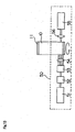
- Fig. 12 is a schematic view of a laser engraving machine, which is a platemaking apparatus in an embodiment of this invention.
- the recording head 30 includes a single laser source 31, a beam splitter 41 for dividing a laser beam emitted from the laser source 31 into a first laser beam L1 and a second laser beam L2, an AOM 32 for modulating the first laser beam L1, an AOD 33 for causing the first laser beam L1 modulated by the AOM 32 to scan axially of the recording drum 11, an AOM 34 for modulating the second laser beam L2, a beam diameter changing device 36 for changing the diameter of the second laser beam L2 modulated by the AOM 34, a pair of deflecting mirrors 42 and 43, a synthesizing device 44 for synthesizing the first laser beam L1 deflected by the AOD 33 and the second laser beam L2 modulated by the AOD 34, and an optic 35 for condensing the first and second laser beams L1 and L2 synthesized by the synthesizing device 44 on a flexo sensitive material 10.
- the other aspects of the construction are the same as in the laser engraving machine in the first embodiment described hereinbefore.
Landscapes
- Engineering & Computer Science (AREA)
- Physics & Mathematics (AREA)
- Optics & Photonics (AREA)
- Plasma & Fusion (AREA)
- Manufacturing & Machinery (AREA)
- Manufacture Or Reproduction Of Printing Formes (AREA)
- Exposure And Positioning Against Photoresist Photosensitive Materials (AREA)
- Glass Compositions (AREA)
- Organic Low-Molecular-Weight Compounds And Preparation Thereof (AREA)
- Steroid Compounds (AREA)
Claims (4)
- Plattenherstellungsvorrichtung zur Herstellung einer Druckplatte, wobei die Plattenhersteliungsvorrichtung aufweist:eine Aufzeichnungstrommel (11), weich mit einem auf ihrem Umfang angebrachten Aufzeichnungsmaterial (10) drehbar ist;eine Laserquelle (31);einen Strahlenteiler (41) zur Unterteilung eines von der Laserquelle emittierten Laserbündels in ein erstes Laserbündel (L1) und ein zweites Laserbündel (L2);eine Bündeldurchmesseränderungsvorrichtung (36) zur Änderung eines Durchmessers des ersten Laserbündels (L1) und/oder des zweiten Laserbündels (L2);eine erste Modulationsvorrichtung (32) zum Modulieren des ersten Laserbündel;einen Ablenker (33) zur Bewirkung, dass das mit der ersten Modulationsvorrichtung modulierte erste Laserbündel axial zur Aufzeichnungstrommel abtastet;eine zweite Modulationsvorrichtung (34) zum Modulieren des zweiten Laserbündel;eine Verschmelzungsvorrichtung (44) zur Verschmelzung des mit dem Ablenker abgelenkten ersten Laserbündel und des mit der zweiten Modulationsvorrichtung modulierten zweiten Laserbündel;eine Optik (35) zur Konzentrierung der mit der Verschmelzungvorrichtung verschmolzenen ersten und zweiten Laserbündels auf dem Aufzeichnungsmaterial; undeine Abtastvorrichtung zur Bewirkung, dass das erste und das zweite Laserbündel, die die Optik durchlaufen haben und auf dem Aufzeichnungsmaterial konzentriert worden sind, synchron und axial zur Aufzeichnungstrommel abtasten;wobei das erste Laserbündel (L1) einen ersten Bündeldurchmesser auf dem Aufzeichnungsmaterial hat und das Aufzeichnungsmaterial mit einem ersten Pixelabstand abtastet, um so das Aufzeichnungsmaterial auf eine erste Tiefe zu gravieren;wobei das zweite Faserbündel (L2) auf dem Aufzeichnungsmaterial einen zweiten Bündeldurchmesser hat, der größer als der erste Bündeldurchmesser ist, und das Aufzeichnungsmaterial mit einem zweiten Pixelabstand bestrahlt, der größer als der erste Pixelabstand ist, um so das Aufzeichnungsmaterial auf eine zweite Tiefe, die größer als die erste Tiefe ist, zu gravieren; undwobei der Ablenker (33) bewirkt, dass das erste Laserbündel das Aufzeichnungsmaterial mit dem zweiten Pixelabstand axial zur Aufzeichnungstrommel abtastet.
- Plattenherstellungsvorrichtung nach Anspruch 1, wobei die folgende Gleichung erfüllt ist:
 wobei F1 eine Abtastfrequenz des ersten Laserbündefs axial zur Aufzeichnungstrommel ist;F2 eine Modulationsfrequenz der zweiten Flodulationsvorrichtung ist;pp der erste Pixelabstand ist; undpc der zweite Pixelabstand ist.
 - Plattenherstellungsvorrichtung nach Anspruch 1, wobei die erste Moduiationsvorrichtung und die zweite Modulationsvorrichtung Modulatoren (22, 32, 25, 34) sind.
- Plattenherstellungsvorrichtung nach Anspruch 1, wobei die erste Modulationsvorrichtung ein Modulator (53) ist, und die zweite Miodulationsvorrichtung eine Vorrichtung zur Steuerung der zweiten Laserquelle und Bewirkung, dass die zweite Laserquelle das zweite Laserbündel moduliert emittiert, ist.
Priority Applications (1)
| Application Number | Priority Date | Filing Date | Title |
|---|---|---|---|
| DE602006000434T DE602006000434T3 (de) | 2005-03-08 | 2006-02-21 | Druckplattenherstellungsgerät |
Applications Claiming Priority (1)
| Application Number | Priority Date | Filing Date | Title |
|---|---|---|---|
| JP2005063414A JP4703222B2 (ja) | 2005-03-08 | 2005-03-08 | 印刷版の製版装置 |
Publications (3)
| Publication Number | Publication Date |
|---|---|
| EP1700691A1 EP1700691A1 (de) | 2006-09-13 |
| EP1700691B1 EP1700691B1 (de) | 2008-01-16 |
| EP1700691B2 true EP1700691B2 (de) | 2010-12-29 |
Family
ID=36407967
Family Applications (1)
| Application Number | Title | Priority Date | Filing Date |
|---|---|---|---|
| EP06003518A Not-in-force EP1700691B2 (de) | 2005-03-08 | 2006-02-21 | Druckplattenherstellungsgerät |
Country Status (6)
| Country | Link |
|---|---|
| US (1) | US7800638B2 (de) |
| EP (1) | EP1700691B2 (de) |
| JP (1) | JP4703222B2 (de) |
| CN (1) | CN100542807C (de) |
| AT (1) | ATE383945T1 (de) |
| DE (1) | DE602006000434T3 (de) |
Families Citing this family (32)
| Publication number | Priority date | Publication date | Assignee | Title |
|---|---|---|---|---|
| DE102006052380B4 (de) * | 2006-11-07 | 2013-04-25 | Mühlbauer Ag | Vorrichtung und Verfahren zum Einbringen von Informationen in einen Datenträger |
| US7827912B2 (en) * | 2006-12-22 | 2010-11-09 | Eastman Kodak Company | Hybrid optical head for direct engraving of flexographic printing plates |
| US8621996B2 (en) * | 2007-08-27 | 2014-01-07 | Eastman Kodak Company | Engraving of printing plates |
| JP2009142865A (ja) * | 2007-12-14 | 2009-07-02 | Keyence Corp | レーザ加工装置、レーザ加工方法及びレーザ加工装置の設定方法 |
| US8418612B2 (en) * | 2008-03-07 | 2013-04-16 | Fujifilm Corporation | Printing plate making apparatus and printing plate making method |
| FR2929439B1 (fr) * | 2008-03-28 | 2013-11-08 | Commissariat Energie Atomique | Procede de stockage d'images et support de stockage correspondant. |
| EP2153991B1 (de) | 2008-08-11 | 2011-08-03 | Agfa Graphics N.V. | Abbildungsvorrichtung und Verfahren zur Herstellung flexografischer Druckvorlagen |
| US8563892B2 (en) * | 2008-09-24 | 2013-10-22 | Standex International Corporation | Method and apparatus for laser engraving |
| JP5009275B2 (ja) * | 2008-12-05 | 2012-08-22 | 富士フイルム株式会社 | マルチビーム露光走査方法及び装置並びに印刷版の製造方法 |
| EP2199081B1 (de) | 2008-12-19 | 2013-02-27 | Agfa Graphics N.V. | Tintenstrahldruckvorrichtung und Verfahren zur Herstellung flexografischer Druckplatten |
| EP2199082B1 (de) | 2008-12-19 | 2013-09-04 | Agfa Graphics N.V. | Verfahren zur Herstellung flexografischer Druckvorlagen |
| US20110014573A1 (en) * | 2009-07-14 | 2011-01-20 | Eynat Matzner | System for engraving flexographic plates |
| JP5500716B2 (ja) * | 2010-02-17 | 2014-05-21 | 富士フイルム株式会社 | レリーフ製造装置およびレリーフ製造方法 |
| CN101804720A (zh) * | 2010-03-16 | 2010-08-18 | 浙江博玛数码电子有限公司 | 基于视觉的数字式电子雕刻制版质量在线监控方法和装置 |
| US8365662B2 (en) * | 2010-05-17 | 2013-02-05 | Eastman Kodak Company | Direct engraving of flexographic printing plates |
| US20110278767A1 (en) * | 2010-05-17 | 2011-11-17 | David Aviel | Direct engraving of flexographic printing plates |
| CN102173178B (zh) * | 2011-02-22 | 2014-03-05 | 苏州华必大激光有限公司 | 具有不等间距的激光成像装置及方法 |
| US20120240802A1 (en) * | 2011-03-22 | 2012-09-27 | Landry-Coltrain Christine J | Laser-engraveable flexographic printing precursors |
| CN102229280A (zh) * | 2011-04-15 | 2011-11-02 | 北京罗赛尔科技有限公司 | 激光高速多路雕刻实现方法 |
| US8613999B2 (en) | 2011-07-28 | 2013-12-24 | Eastman Kodak Company | Laser-engraveable compositions and flexographic printing precursors comprising organic porous particles |
| US8603725B2 (en) | 2011-07-28 | 2013-12-10 | Eastman Kodak Company | Laser-engraveable compositions and flexographic printing precursors |
| US20140233080A1 (en) * | 2013-02-15 | 2014-08-21 | Xerox Corporation | Multi-Beam ROS Imaging System |
| EP2778784B8 (de) | 2013-03-11 | 2022-02-23 | Esko-Graphics Imaging GmbH | Vorrichtung und Verfahren zur direkten Mehrstrahlengravur elastomerer Druckplatten und -hülsen |
| CN103197509B (zh) * | 2013-03-16 | 2015-05-06 | 陈乃奇 | 一种回转面用激光旋转直接曝光成像装置及方法 |
| WO2015053757A1 (en) | 2013-10-09 | 2015-04-16 | Eastman Kodak Company | Direct laser-engraveable patternable elements and uses |
| CN105235360A (zh) * | 2015-10-15 | 2016-01-13 | 鹤山市精工制版有限公司 | 一种版辊激光直雕处理方法及其系统 |
| CN110072686B (zh) | 2016-12-20 | 2021-09-28 | 爱克发有限公司 | 柔版制版机和制备柔版的方法 |
| CN108857073B (zh) * | 2018-06-15 | 2021-06-25 | 常州天寅智造科技股份有限公司 | 雕刻控制方法及雕刻系统 |
| CN109109457B (zh) * | 2018-08-03 | 2022-05-24 | 常州龙润激光科技有限公司 | 一种网纹辊及其制造方法 |
| CN113478948B (zh) * | 2021-07-01 | 2022-12-02 | 绍兴鑫昌印花机械科技有限公司 | 一种双激光制网机 |
| CN113231745B (zh) * | 2021-07-12 | 2022-02-15 | 中钞印制技术研究院有限公司 | 激光雕刻制版设备、控制系统、制版方法以及存储介质 |
| EP4241992A1 (de) * | 2022-03-09 | 2023-09-13 | AKK GmbH | Mehrfach-lasergravur |
Citations (1)
| Publication number | Priority date | Publication date | Assignee | Title |
|---|---|---|---|---|
| DE10116672A1 (de) † | 2000-04-08 | 2001-10-18 | Heinrich Juergensen | Verfahren und Vorrichtung zur Materialbearbeitung |
Family Cites Families (14)
| Publication number | Priority date | Publication date | Assignee | Title |
|---|---|---|---|---|
| US4064205A (en) * | 1974-07-02 | 1977-12-20 | Logetronics, Inc. | Method for making a printing plate from a porous substrate |
| GB9009406D0 (en) * | 1990-04-26 | 1990-06-20 | Zed Instr Ltd | Printing cylinder engraving |
| DE4212546C1 (de) * | 1992-04-15 | 1993-03-11 | Joachim Dr. Scheerer | |
| US5557303A (en) * | 1992-10-14 | 1996-09-17 | Fuji Photo Film Co., Ltd. | Thermal recording apparatus which can draw black borders |
| JPH06234086A (ja) * | 1993-02-10 | 1994-08-23 | Sony Corp | レーザ製版装置 |
| DE4313111C2 (de) * | 1993-04-22 | 1999-05-06 | Roland Man Druckmasch | Verfahren zur Herstellung einer druckenden Vorlage, insbesondere einer Druckform einer Druckmaschine |
| DE19544502C1 (de) | 1995-11-29 | 1997-05-15 | Baasel Scheel Lasergraphics Gm | Lasergravuranlage |
| JP3302974B2 (ja) * | 2000-11-08 | 2002-07-15 | 株式会社金田機械製作所 | 印刷用刷版の画素密度複数段同時露光方法及びその装置 |
| JP3273139B1 (ja) * | 2000-11-08 | 2002-04-08 | 株式会社金田機械製作所 | 印刷用刷版の画素密度複数段順次露光方法及びその装置 |
| JP3400790B2 (ja) * | 2001-05-10 | 2003-04-28 | 株式会社金田機械製作所 | レーザ直接描画方式による新聞印刷用の見開き刷版の製造方法 |
| ATE282526T1 (de) | 2001-05-25 | 2004-12-15 | Stork Prints Austria Gmbh | Verfahren und vorrichtung zur herstellung einer druckform |
| US6900826B2 (en) * | 2002-02-19 | 2005-05-31 | Presstek, Inc. | Multiple resolution helical imaging system and method |
| US7126619B2 (en) * | 2002-05-31 | 2006-10-24 | Buzz Sales Company, Inc. | System and method for direct laser engraving of images onto a printing substrate |
| JP2004286175A (ja) | 2003-03-25 | 2004-10-14 | Koyo Seiko Co Ltd | 磁気軸受装置 |
-
2005
- 2005-03-08 JP JP2005063414A patent/JP4703222B2/ja not_active Expired - Fee Related
-
2006
- 2006-02-21 AT AT06003518T patent/ATE383945T1/de not_active IP Right Cessation
- 2006-02-21 EP EP06003518A patent/EP1700691B2/de not_active Not-in-force
- 2006-02-21 DE DE602006000434T patent/DE602006000434T3/de active Active
- 2006-03-08 US US11/370,019 patent/US7800638B2/en not_active Expired - Fee Related
- 2006-03-08 CN CNB2006100588841A patent/CN100542807C/zh not_active Expired - Fee Related
Patent Citations (1)
| Publication number | Priority date | Publication date | Assignee | Title |
|---|---|---|---|---|
| DE10116672A1 (de) † | 2000-04-08 | 2001-10-18 | Heinrich Juergensen | Verfahren und Vorrichtung zur Materialbearbeitung |
Also Published As
| Publication number | Publication date |
|---|---|
| US7800638B2 (en) | 2010-09-21 |
| US20060203861A1 (en) | 2006-09-14 |
| ATE383945T1 (de) | 2008-02-15 |
| DE602006000434D1 (de) | 2008-03-06 |
| JP2006250983A (ja) | 2006-09-21 |
| EP1700691A1 (de) | 2006-09-13 |
| EP1700691B1 (de) | 2008-01-16 |
| DE602006000434T2 (de) | 2009-01-15 |
| JP4703222B2 (ja) | 2011-06-15 |
| CN1830664A (zh) | 2006-09-13 |
| CN100542807C (zh) | 2009-09-23 |
| DE602006000434T3 (de) | 2011-06-30 |
Similar Documents
| Publication | Publication Date | Title |
|---|---|---|
| EP1700691B2 (de) | Druckplattenherstellungsgerät | |
| EP1642712B1 (de) | Verfahren zur Herstellung einer Druckplatte und Druckplattenherstellungsgerät | |
| US6150629A (en) | Laser engraving system | |
| CN1754694B (zh) | 印刷版的制版方法以及印刷版的制版装置 | |
| JP3556204B2 (ja) | 印刷ブロックを製造する方法及び装置 | |
| EP2097260B1 (de) | Direktgravur von flexodruckplatten | |
| US20020189471A1 (en) | Method and device for producing a printing block | |
| CN104979748B (zh) | 飞秒激光扫描功率调控装置和方法、飞秒激光加工系统 | |
| JP2006224481A (ja) | 印刷版の製版装置 | |
| JP2006119427A (ja) | レーザ加工方法及びレーザ加工装置及びにこれよって作製された構造体 | |
| WO2021205756A1 (ja) | レーザ加工装置及びレーザ加工方法 | |
| JPH10166167A (ja) | レーザマーキング方法及び装置 | |
| US5825503A (en) | Engraving apparatus and method for adjusting a worn stylus using a midtone correction | |
| WO1997038820A1 (fr) | Masque a cristaux liquides, marqueur laser a cristaux liquides et procede de marquage au moyen de celui-ci | |
| GB2030929A (en) | Gravure printing formes | |
| JP2006227261A (ja) | 印刷版の製版装置 | |
| US8553290B2 (en) | Plate-making apparatus and printing plate manufacturing method | |
| JP2006159800A (ja) | 印刷版の製版方法および印刷版の製版装置 | |
| RU2080971C1 (ru) | Способ лазерного гравирования | |
| JPH10315425A (ja) | レーザ製版装置 | |
| JP3355631B2 (ja) | レーザ製版装置及び製版方法 | |
| JPH07124763A (ja) | ビームスキャン式レーザマーキング装置 | |
| WO2021205755A1 (ja) | レーザ加工装置及びレーザ加工方法 | |
| JPH10323772A (ja) | レーザマーカにおける刻印位置制御装置 | |
| JPH07246482A (ja) | レーザマーキング装置 |
Legal Events
| Date | Code | Title | Description |
|---|---|---|---|
| PUAI | Public reference made under article 153(3) epc to a published international application that has entered the european phase |
Free format text: ORIGINAL CODE: 0009012 |
|
| AK | Designated contracting states |
Kind code of ref document: A1 Designated state(s): AT BE BG CH CY CZ DE DK EE ES FI FR GB GR HU IE IS IT LI LT LU LV MC NL PL PT RO SE SI SK TR |
|
| AX | Request for extension of the european patent |
Extension state: AL BA HR MK YU |
|
| 17P | Request for examination filed |
Effective date: 20061213 |
|
| AKX | Designation fees paid |
Designated state(s): AT BE BG CH CY CZ DE DK EE ES FI FR GB GR HU IE IS IT LI LT LU LV MC NL PL PT RO SE SI SK TR |
|
| GRAP | Despatch of communication of intention to grant a patent |
Free format text: ORIGINAL CODE: EPIDOSNIGR1 |
|
| GRAS | Grant fee paid |
Free format text: ORIGINAL CODE: EPIDOSNIGR3 |
|
| GRAA | (expected) grant |
Free format text: ORIGINAL CODE: 0009210 |
|
| AK | Designated contracting states |
Kind code of ref document: B1 Designated state(s): AT BE BG CH CY CZ DE DK EE ES FI FR GB GR HU IE IS IT LI LT LU LV MC NL PL PT RO SE SI SK TR |
|
| REG | Reference to a national code |
Ref country code: GB Ref legal event code: FG4D |
|
| REG | Reference to a national code |
Ref country code: CH Ref legal event code: EP |
|
| REG | Reference to a national code |
Ref country code: IE Ref legal event code: FG4D |
|
| REF | Corresponds to: |
Ref document number: 602006000434 Country of ref document: DE Date of ref document: 20080306 Kind code of ref document: P |
|
| PG25 | Lapsed in a contracting state [announced via postgrant information from national office to epo] |
Ref country code: NL Free format text: LAPSE BECAUSE OF FAILURE TO SUBMIT A TRANSLATION OF THE DESCRIPTION OR TO PAY THE FEE WITHIN THE PRESCRIBED TIME-LIMIT Effective date: 20080116 |
|
| NLV1 | Nl: lapsed or annulled due to failure to fulfill the requirements of art. 29p and 29m of the patents act | ||
| ET | Fr: translation filed | ||
| PG25 | Lapsed in a contracting state [announced via postgrant information from national office to epo] |
Ref country code: LT Free format text: LAPSE BECAUSE OF FAILURE TO SUBMIT A TRANSLATION OF THE DESCRIPTION OR TO PAY THE FEE WITHIN THE PRESCRIBED TIME-LIMIT Effective date: 20080116 Ref country code: CH Free format text: LAPSE BECAUSE OF FAILURE TO SUBMIT A TRANSLATION OF THE DESCRIPTION OR TO PAY THE FEE WITHIN THE PRESCRIBED TIME-LIMIT Effective date: 20080116 Ref country code: FI Free format text: LAPSE BECAUSE OF FAILURE TO SUBMIT A TRANSLATION OF THE DESCRIPTION OR TO PAY THE FEE WITHIN THE PRESCRIBED TIME-LIMIT Effective date: 20080116 Ref country code: IS Free format text: LAPSE BECAUSE OF FAILURE TO SUBMIT A TRANSLATION OF THE DESCRIPTION OR TO PAY THE FEE WITHIN THE PRESCRIBED TIME-LIMIT Effective date: 20080516 Ref country code: ES Free format text: LAPSE BECAUSE OF FAILURE TO SUBMIT A TRANSLATION OF THE DESCRIPTION OR TO PAY THE FEE WITHIN THE PRESCRIBED TIME-LIMIT Effective date: 20080427 Ref country code: LI Free format text: LAPSE BECAUSE OF FAILURE TO SUBMIT A TRANSLATION OF THE DESCRIPTION OR TO PAY THE FEE WITHIN THE PRESCRIBED TIME-LIMIT Effective date: 20080116 |
|
| REG | Reference to a national code |
Ref country code: CH Ref legal event code: PL |
|
| PG25 | Lapsed in a contracting state [announced via postgrant information from national office to epo] |
Ref country code: AT Free format text: LAPSE BECAUSE OF FAILURE TO SUBMIT A TRANSLATION OF THE DESCRIPTION OR TO PAY THE FEE WITHIN THE PRESCRIBED TIME-LIMIT Effective date: 20080116 Ref country code: BG Free format text: LAPSE BECAUSE OF FAILURE TO SUBMIT A TRANSLATION OF THE DESCRIPTION OR TO PAY THE FEE WITHIN THE PRESCRIBED TIME-LIMIT Effective date: 20080416 |
|
| PG25 | Lapsed in a contracting state [announced via postgrant information from national office to epo] |
Ref country code: PT Free format text: LAPSE BECAUSE OF FAILURE TO SUBMIT A TRANSLATION OF THE DESCRIPTION OR TO PAY THE FEE WITHIN THE PRESCRIBED TIME-LIMIT Effective date: 20080616 Ref country code: PL Free format text: LAPSE BECAUSE OF FAILURE TO SUBMIT A TRANSLATION OF THE DESCRIPTION OR TO PAY THE FEE WITHIN THE PRESCRIBED TIME-LIMIT Effective date: 20080116 Ref country code: BE Free format text: LAPSE BECAUSE OF FAILURE TO SUBMIT A TRANSLATION OF THE DESCRIPTION OR TO PAY THE FEE WITHIN THE PRESCRIBED TIME-LIMIT Effective date: 20080116 Ref country code: LV Free format text: LAPSE BECAUSE OF FAILURE TO SUBMIT A TRANSLATION OF THE DESCRIPTION OR TO PAY THE FEE WITHIN THE PRESCRIBED TIME-LIMIT Effective date: 20080116 Ref country code: SI Free format text: LAPSE BECAUSE OF FAILURE TO SUBMIT A TRANSLATION OF THE DESCRIPTION OR TO PAY THE FEE WITHIN THE PRESCRIBED TIME-LIMIT Effective date: 20080116 |
|
| PG25 | Lapsed in a contracting state [announced via postgrant information from national office to epo] |
Ref country code: CZ Free format text: LAPSE BECAUSE OF FAILURE TO SUBMIT A TRANSLATION OF THE DESCRIPTION OR TO PAY THE FEE WITHIN THE PRESCRIBED TIME-LIMIT Effective date: 20080116 Ref country code: SK Free format text: LAPSE BECAUSE OF FAILURE TO SUBMIT A TRANSLATION OF THE DESCRIPTION OR TO PAY THE FEE WITHIN THE PRESCRIBED TIME-LIMIT Effective date: 20080116 Ref country code: DK Free format text: LAPSE BECAUSE OF FAILURE TO SUBMIT A TRANSLATION OF THE DESCRIPTION OR TO PAY THE FEE WITHIN THE PRESCRIBED TIME-LIMIT Effective date: 20080116 Ref country code: MC Free format text: LAPSE BECAUSE OF NON-PAYMENT OF DUE FEES Effective date: 20080228 Ref country code: SE Free format text: LAPSE BECAUSE OF FAILURE TO SUBMIT A TRANSLATION OF THE DESCRIPTION OR TO PAY THE FEE WITHIN THE PRESCRIBED TIME-LIMIT Effective date: 20080416 |
|
| PLBI | Opposition filed |
Free format text: ORIGINAL CODE: 0009260 |
|
| PLAX | Notice of opposition and request to file observation + time limit sent |
Free format text: ORIGINAL CODE: EPIDOSNOBS2 |
|
| PG25 | Lapsed in a contracting state [announced via postgrant information from national office to epo] |
Ref country code: RO Free format text: LAPSE BECAUSE OF FAILURE TO SUBMIT A TRANSLATION OF THE DESCRIPTION OR TO PAY THE FEE WITHIN THE PRESCRIBED TIME-LIMIT Effective date: 20080116 |
|
| 26 | Opposition filed |
Opponent name: STORK PRINTS AUSTRIA GMBH Effective date: 20081016 |
|
| PG25 | Lapsed in a contracting state [announced via postgrant information from national office to epo] |
Ref country code: IE Free format text: LAPSE BECAUSE OF NON-PAYMENT OF DUE FEES Effective date: 20080221 Ref country code: EE Free format text: LAPSE BECAUSE OF FAILURE TO SUBMIT A TRANSLATION OF THE DESCRIPTION OR TO PAY THE FEE WITHIN THE PRESCRIBED TIME-LIMIT Effective date: 20080116 |
|
| PLAF | Information modified related to communication of a notice of opposition and request to file observations + time limit |
Free format text: ORIGINAL CODE: EPIDOSCOBS2 |
|
| PLBB | Reply of patent proprietor to notice(s) of opposition received |
Free format text: ORIGINAL CODE: EPIDOSNOBS3 |
|
| PG25 | Lapsed in a contracting state [announced via postgrant information from national office to epo] |
Ref country code: CY Free format text: LAPSE BECAUSE OF FAILURE TO SUBMIT A TRANSLATION OF THE DESCRIPTION OR TO PAY THE FEE WITHIN THE PRESCRIBED TIME-LIMIT Effective date: 20080116 |
|
| PG25 | Lapsed in a contracting state [announced via postgrant information from national office to epo] |
Ref country code: IT Free format text: LAPSE BECAUSE OF FAILURE TO SUBMIT A TRANSLATION OF THE DESCRIPTION OR TO PAY THE FEE WITHIN THE PRESCRIBED TIME-LIMIT Effective date: 20080116 |
|
| PG25 | Lapsed in a contracting state [announced via postgrant information from national office to epo] |
Ref country code: HU Free format text: LAPSE BECAUSE OF FAILURE TO SUBMIT A TRANSLATION OF THE DESCRIPTION OR TO PAY THE FEE WITHIN THE PRESCRIBED TIME-LIMIT Effective date: 20080717 Ref country code: LU Free format text: LAPSE BECAUSE OF NON-PAYMENT OF DUE FEES Effective date: 20080221 |
|
| PG25 | Lapsed in a contracting state [announced via postgrant information from national office to epo] |
Ref country code: TR Free format text: LAPSE BECAUSE OF FAILURE TO SUBMIT A TRANSLATION OF THE DESCRIPTION OR TO PAY THE FEE WITHIN THE PRESCRIBED TIME-LIMIT Effective date: 20080116 |
|
| PG25 | Lapsed in a contracting state [announced via postgrant information from national office to epo] |
Ref country code: GR Free format text: LAPSE BECAUSE OF FAILURE TO SUBMIT A TRANSLATION OF THE DESCRIPTION OR TO PAY THE FEE WITHIN THE PRESCRIBED TIME-LIMIT Effective date: 20080417 |
|
| PUAH | Patent maintained in amended form |
Free format text: ORIGINAL CODE: 0009272 |
|
| STAA | Information on the status of an ep patent application or granted ep patent |
Free format text: STATUS: PATENT MAINTAINED AS AMENDED |
|
| 27A | Patent maintained in amended form |
Effective date: 20101229 |
|
| AK | Designated contracting states |
Kind code of ref document: B2 Designated state(s): AT BE BG CH CY CZ DE DK EE ES FI FR GB GR HU IE IS IT LI LT LU LV MC NL PL PT RO SE SI SK TR |
|
| PGFP | Annual fee paid to national office [announced via postgrant information from national office to epo] |
Ref country code: FR Payment date: 20120221 Year of fee payment: 7 |
|
| REG | Reference to a national code |
Ref country code: DE Ref legal event code: R082 Ref document number: 602006000434 Country of ref document: DE Representative=s name: KILIAN KILIAN & PARTNER, DE |
|
| REG | Reference to a national code |
Ref country code: FR Ref legal event code: ST Effective date: 20131031 |
|
| PG25 | Lapsed in a contracting state [announced via postgrant information from national office to epo] |
Ref country code: FR Free format text: LAPSE BECAUSE OF NON-PAYMENT OF DUE FEES Effective date: 20130228 |
|
| REG | Reference to a national code |
Ref country code: DE Ref legal event code: R082 Ref document number: 602006000434 Country of ref document: DE Representative=s name: KILIAN KILIAN & PARTNER, DE |
|
| REG | Reference to a national code |
Ref country code: DE Ref legal event code: R081 Ref document number: 602006000434 Country of ref document: DE Owner name: SCREEN HOLDINGS CO., LTD., JP Free format text: FORMER OWNER: DAINIPPON SCREEN MFG. CO., LTD., KYOTO, JP Effective date: 20150317 Ref country code: DE Ref legal event code: R082 Ref document number: 602006000434 Country of ref document: DE Representative=s name: KILIAN KILIAN & PARTNER, DE Effective date: 20150317 Ref country code: DE Ref legal event code: R082 Ref document number: 602006000434 Country of ref document: DE Representative=s name: KILIAN KILIAN & PARTNER, DE Effective date: 20130130 |
|
| PGFP | Annual fee paid to national office [announced via postgrant information from national office to epo] |
Ref country code: DE Payment date: 20150218 Year of fee payment: 10 |
|
| PGFP | Annual fee paid to national office [announced via postgrant information from national office to epo] |
Ref country code: GB Payment date: 20150218 Year of fee payment: 10 |
|
| REG | Reference to a national code |
Ref country code: DE Ref legal event code: R119 Ref document number: 602006000434 Country of ref document: DE |
|
| GBPC | Gb: european patent ceased through non-payment of renewal fee |
Effective date: 20160221 |
|
| PG25 | Lapsed in a contracting state [announced via postgrant information from national office to epo] |
Ref country code: GB Free format text: LAPSE BECAUSE OF NON-PAYMENT OF DUE FEES Effective date: 20160221 Ref country code: DE Free format text: LAPSE BECAUSE OF NON-PAYMENT OF DUE FEES Effective date: 20160901 |