EP1699985B1 - Luftdichte blockhauseckenkonstruktion - Google Patents
Luftdichte blockhauseckenkonstruktion Download PDFInfo
- Publication number
- EP1699985B1 EP1699985B1 EP04801226A EP04801226A EP1699985B1 EP 1699985 B1 EP1699985 B1 EP 1699985B1 EP 04801226 A EP04801226 A EP 04801226A EP 04801226 A EP04801226 A EP 04801226A EP 1699985 B1 EP1699985 B1 EP 1699985B1
- Authority
- EP
- European Patent Office
- Prior art keywords
- corner
- logs
- short
- log
- windproof
- Prior art date
- Legal status (The legal status is an assumption and is not a legal conclusion. Google has not performed a legal analysis and makes no representation as to the accuracy of the status listed.)
- Expired - Lifetime
Links
Images

Classifications
-
- E—FIXED CONSTRUCTIONS
- E04—BUILDING
- E04B—GENERAL BUILDING CONSTRUCTIONS; WALLS, e.g. PARTITIONS; ROOFS; FLOORS; CEILINGS; INSULATION OR OTHER PROTECTION OF BUILDINGS
- E04B2/00—Walls, e.g. partitions, for buildings; Wall construction with regard to insulation; Connections specially adapted to walls
- E04B2/56—Load-bearing walls of framework or pillarwork; Walls incorporating load-bearing elongated members
- E04B2/70—Load-bearing walls of framework or pillarwork; Walls incorporating load-bearing elongated members with elongated members of wood
- E04B2/701—Load-bearing walls of framework or pillarwork; Walls incorporating load-bearing elongated members with elongated members of wood with integrated supporting and obturation function
- E04B2/705—Load-bearing walls of framework or pillarwork; Walls incorporating load-bearing elongated members with elongated members of wood with integrated supporting and obturation function with longitudinal horizontal elements placed between columns
Definitions
- the invention relates to a short-corner structure of a log building, having logs of a first wall and logs of a second wall, which are fastened to each other at a corner, and which corner is covered by corner boards and at least one layer of windproof material between the logs and the corner boards.
- Log construction is a traditional method of building wooden houses. At the corners of log buildings, the logs of the walls intersect each other, forming a corner joint.
- corner joints There are two different basic types of corner joints. In the type of corner joint, which is most commonly used, the end of the log continues as "long" past the point of the joint, whereby an overhang holding the corner joint together is formed in the part of the log that extends past the corner. The end of the log also protects the joint from the strain of the weather, such as wind and rain.
- the other basic type of corner joints is the so-called “short corner", in which the ends of the logs reach to the same level as the exterior surfaces of the walls at the corners or only a little over them. Short-corner joints are often covered by corner boards.
- Uncontrolled air leakage taking place through the corner joints is a known problem in log buildings.
- the problem is especially pronounced in short-corner joints, where there is no "overhanging" part of the corner to protect the corner joint.
- Uncontrolled air leakage through the corners impairs the energy economy of a log building and increases heating costs.
- the poor airtightness of log buildings partly accounts for the fact that expensive additional insulation is required for making the heat insulation level of log buildings to comply with the regulations. Air leakage also impairs the operation of ventilation equipment and makes it more difficult to achieve controlled ventilation in the interior of the building. Air leakages also cause a sense of draught to the inhabitants and thus weaken the comfort of living.
- the publication US 20020157334 discloses a building method in which log-like elements built up of lamellas glued together are used. The ends of the elements are connected to each other by an elongated corner piece made of steel, which is used in the corner joints of the building. The corner structure is covered by corner boards on the outside. Because the windstop materials used in wooden buildings must be highly permeable to water vapor, it is clear that the steel corner piece described in the publication is intended merely as a joining piece of the elements, and it is thus not intended to function as a windstop layer to improve the airtightness of the corner.
- Document GB-A-245035 discloses a short-corner structure of a log building having logs of a first wall and logs of a second wall, which are fastened to each other at a corner with the aid of angle shaped clamping plates. The corner is covered by corner boards. No change of air takes place behind the corner boards, and therefore humidity possibly carried through the short-corner structure can accumulate behind the corner boards.
- the invention relates to a short-corner structure of a log building, in which the logs of the first wall and the logs of the second wall are fastened to each other by a corner joint, forming thus the corner of the building.
- the corner joint is preferably a locking joint, which interlocks the ends of the logs as immobile in relation to each other.
- the short-corner structure is covered from the outside by vertical corner boards installed on the corner, the primary task of which is to protect the ends of the logs from the strain of the weather and to prevent the access of water and wind to the gaps and seams of the corner joint structure.
- the basic idea of the invention is that at least one layer of windstop material is arranged on the corner area, with the purpose of improving the airtightness of the short-corner structure. Between the windstop material and the corner board there is a ventilation gap. The windstop material is fastened to the exterior surface of the log so that in the complete structure it remains invisible under the corner boards.
- the windstop material to be used is preferably windproof paper
- an end thinning is cut on the outer surfaces of the ends of the logs.
- the distance of the edge of the end thinning from the outer corner is larger than the width of the log at the end thinning.
- the corner structure comprises a corner batten fastened at the edge of the end thinning, and the edges of the windproof paper are extended under the corner battens.
- An advantage of the invention is the fact that it improves the energy economy of log buildings significantly, which is seen as savings in the heating costs of the building.
- Another advantage of the invention is the fact that it reduces the sense of draught inside the building, which improves the comfort of living.
- a further advantage of the invention is the fact that the ventilation systems of a log building work better, because uncontrolled air leakage is reduced.
- Yet another advantage of the invention is the fact that for its part it helps to achieve the regulatory level of heat insulation and ventilation in log buildings.
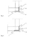
- Fig. 1 presents an example of a short-corner structure of a log building according to the invention as a horizontal section.
- the log building is manufactured in the well-known manner from logs placed horizontally on top of each other. At the corners of the walls, where the logs intersect, notches are cut at the ends of the logs to form the corner joint by which the logs are connected to each other.
- the logs of the first wall 1 and the logs of the second wall 2 are connected to each other by a locking joint known as such so that a corner joint shown by the drawing is formed.
- End thinnings 4 have been made on the outer surfaces of the ends of the logs in the area of the short-corner structure so that the plane of the end thinning is essentially parallel with the plane of the exterior surface of the logs.
- the depth of the end thinning can be selected suitably, preferably the depth of the end thinning is 2-3 cm.
- the width of the end thinning as measured from the end surfaces of the logs is slightly larger than the width of the logs, i.e. the edge 7 of the end thinning is further from the outer corner 14 than the plane of the inner surface 6 of the logs. The joint created on the side of the inner surface of the log thus remains in the area of the end thinning.
- the logs of the first wall 1 have been cut to such a length that the ends of the logs reach to the level of the end thinning 4 of the logs of the second wall.
- the logs of the second wall 2 have been cut so that their ends reach to the level of the end thinning of the logs of the first wall.
- the end surfaces of the logs form planar exterior surfaces of the short-corner structure, which are essentially parallel with the exterior surfaces 3 of the logs.
- the corner joint is symmetrical, and so the difference between the levels of the exterior surfaces of the wall and the end surfaces of the logs is substantially the same on both walls.
- the exterior surface of the short-corner structure according to the invention is entirely covered with windproof paper 8.
- the windproof paper extends as a continuous strip from the edge 7 of the end thinning 4 of the log of the first wall 1 over the outer corner 14 up to the edge of the end thinning on the log of the second wall 2.
- the windproof paper thus entirely covers the gaps and seams exposed at the exterior surface of the short-corner structure, and thereby significantly improves the airtightness of the short-corner structure.
- the windproof paper is fastened to the logs at the edges by mechanical fastening means, preferably by rivets or staples, which are not shown in the figure.
- Vertical corner battens 9 of the wall are fastened to the edges of the end thinnings so that the edge of the windproof paper remains pressed between the corner batten and the surface of the log. Reliable and airtight fastening of the edges of the windproof paper is ensured by the corner battens.
- the corner battens are fastened to the logs by mechanical fastening means, such as nails or screws.
- strips of windproof board 10 are installed on top of the windproof paper so that the windproof boards extend from the edge of the corner batten up to the outer corner 14. The windproof paper thus becomes entirely covered by either the corner battens or the windproof board.
- the windproof boards are fastened to the logs by mechanical fastening means, such as nails, screws or staples.
- the short-corner structure according to the invention is covered by vertical corner boards 11, the first ends of which are fitted to a slot in the corner battens and the second ends are fastened to a corner bead 12 placed at the joining point.
- the corner boards and the corner bead are fastened in place by mechanical fastening means, such as nails, screws or staples.
- mechanical fastening means such as nails, screws or staples.
- FIGS 2 and 3 Some preferred embodiments of the short-corner structure of a log building according to the invention are shown in Figures 2 and 3 . These embodiments differ from the short-corner structure shown by Fig. 1 in that only one layer of windstop material is used in them.
- the layer of windstop material is windproof paper 8, which covers the whole exterior surface of the short-corner structure.
- the windproof paper is fastened to the wall logs at its edges by means of corner battens 9.
- the exterior surfaces of the short-corner structure are covered by a windproof board 10, which extends from the outer corner 14 up to the edge 7 of the end thinning.
- Fig. 4 presents yet another preferred embodiment of the short-corner structure of a log building according to the invention.
- both a windproof paper 8 and a windproof board 10 are fastened to the exterior interface of the corner.
- No corner battens are used in the corner, but the edges of the corner boards are extended over the edge 7 of the end thinning and fastened directly to the exterior surface of the log.
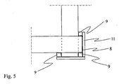
- Fig. 5 presents another short-corner structure of a log building, which does not fall within the scope of the claims.
- the log ends of the first wall extend by a few centimeters over the level of the exterior surface of the logs of the second wall.
- the log ends of the second wall extend in the same way slightly over the level of the exterior surface of the logs of the first wall.
- the overhang is so small that it is clearly a short-corner structure.
- the exceeding over the end of the log is preferably about four centimeters.
- a windproof paper is fastened to the exterior interface of the corner in away that it covers, as a continuous layer, the ends of the logs joined at the corner and the gaps and seams between the logs exposed at the exterior surface of the corner structure.
- the corner structure includes three corner battens 9, which are placed at the corners formed by the logs intersecting at the corner.
- the edges of the windproof paper have been extended under the outermost corner battens 9 of the corner structure, and so the windproof paper remains well in place.
- the corner structure is covered by corner boards 11 in the known manner.
Landscapes
- Engineering & Computer Science (AREA)
- Architecture (AREA)
- Physics & Mathematics (AREA)
- Electromagnetism (AREA)
- Civil Engineering (AREA)
- Structural Engineering (AREA)
- Building Environments (AREA)
- Finishing Walls (AREA)
- Load-Bearing And Curtain Walls (AREA)
- Duct Arrangements (AREA)
- Working Measures On Existing Buildindgs (AREA)
- Pharmaceuticals Containing Other Organic And Inorganic Compounds (AREA)
Claims (7)
- Kurzeckenstruktur eines Blockhauses, das Langhölzer (1) einer ersten Wand und Langhölzer (2) einer zweiten Wand aufweist, die miteinander an einer Ecke befestigt sind, und wobei die Ecke durch Eckbretter (11) und zumindest eine Lage von luftdichtem Material (8, 10) zwischen den Langhölzern und den Eckbrettern abgedeckt ist,
dadurch gekennzeichnet, dass
dort eine Ventilationslücke (13) zwischen dem luftdichten Material (8, 10) und dem Eckbrett ist. - Kurzeckenstruktur nach Anspruch 1, dadurch gekennzeichnet, dass an den äußeren Oberflächen (3) der Langholzenden (1, 2) eine Endverdünnung (4) vorgesehen ist, die an einer Kante (7) endet, wobei ihre Entfernung von der äußeren Ecke (14) größer ist, als die Breite des Langholzes an der Endverdünnung (4).
- Kurzeckenstruktur nach Anspruch 2, dadurch gekennzeichnet, dass die Tiefe der Endverdünnung (4) 2-3cm ist.
- Kurzeckenstruktur nach einem der Ansprüche 1 bis 3, dadurch gekennzeichnet, dass zumindest eine Lage des luftdichten Materials aus luftdichtem Papier ist.
- Kurzeckenstruktur nach Anspruch 4, dadurch gekennzeichnet, dass sie Ecklatten (9) umfasst, die an der Kante (7) der Endverdünnung (4) oder an den Ecken befestigt sind, die durch die Langhölzer (1, 2) ausgebildet sind, die sich an der Ecke schneiden, und dass die Ecken des luftdichten Papiers (8) sich unter die Ecklatten (9) erstrecken.
- Kurzeckenstruktur nach einem der Ansprüche 2 bis 5, dadurch gekennzeichnet, dass zumindest eine Schicht des luftdichten Materials aus einem luftdichten Brett (10) ist.
- Kurzeckenstruktur nach Anspruch 2, dadurch gekennzeichnet, dass zumindest eine Schicht des luftdichten Materials aus einem luftdichten Brett (10) ist und das luftdichte Brett (10) sich von der äußeren Ecke (14) zur kante (7) der Endverdünnung (4) erstreckt.
Applications Claiming Priority (2)
| Application Number | Priority Date | Filing Date | Title |
|---|---|---|---|
| FI20031770A FI20031770A7 (fi) | 2003-12-03 | 2003-12-03 | Ilmatiivis hirsinurkka |
| PCT/FI2004/000729 WO2005054593A1 (en) | 2003-12-03 | 2004-12-02 | Airtight log corner structure |
Publications (2)
| Publication Number | Publication Date |
|---|---|
| EP1699985A1 EP1699985A1 (de) | 2006-09-13 |
| EP1699985B1 true EP1699985B1 (de) | 2010-07-14 |
Family
ID=29763469
Family Applications (1)
| Application Number | Title | Priority Date | Filing Date |
|---|---|---|---|
| EP04801226A Expired - Lifetime EP1699985B1 (de) | 2003-12-03 | 2004-12-02 | Luftdichte blockhauseckenkonstruktion |
Country Status (6)
| Country | Link |
|---|---|
| EP (1) | EP1699985B1 (de) |
| AT (1) | ATE474099T1 (de) |
| DE (1) | DE602004028161D1 (de) |
| FI (1) | FI20031770A7 (de) |
| RU (2) | RU79303U1 (de) |
| WO (1) | WO2005054593A1 (de) |
Citations (1)
| Publication number | Priority date | Publication date | Assignee | Title |
|---|---|---|---|---|
| GB245035A (en) * | 1925-08-21 | 1925-12-31 | Johannes Benjamin Een | Improvements in the corner connections of wooden plank houses |
Family Cites Families (6)
| Publication number | Priority date | Publication date | Assignee | Title |
|---|---|---|---|---|
| US1655701A (en) * | 1927-03-14 | 1928-01-10 | Kenneth M Hyland | Split-log cabin |
| US2304034A (en) * | 1939-07-17 | 1942-12-01 | Kenneth H Dyer | Building construction |
| US3521417A (en) * | 1968-03-25 | 1970-07-21 | Veikko Filadet Onjukka | Building structure |
| US3623288A (en) * | 1970-07-23 | 1971-11-30 | Stanley L Horowitz | Prefabricated building construction |
| US3818653A (en) * | 1973-01-22 | 1974-06-25 | A Williams | Prefabricated building structure |
| US6588161B2 (en) | 2001-04-27 | 2003-07-08 | William Harry Smith | Laminated construction elements and method for constructing an earthquake-resistant building |
-
2003
- 2003-12-03 FI FI20031770A patent/FI20031770A7/fi not_active IP Right Cessation
-
2004
- 2004-12-02 WO PCT/FI2004/000729 patent/WO2005054593A1/en not_active Ceased
- 2004-12-02 AT AT04801226T patent/ATE474099T1/de not_active IP Right Cessation
- 2004-12-02 RU RU2008122271/22U patent/RU79303U1/ru not_active IP Right Cessation
- 2004-12-02 RU RU2006123432/03A patent/RU2006123432A/ru unknown
- 2004-12-02 EP EP04801226A patent/EP1699985B1/de not_active Expired - Lifetime
- 2004-12-02 DE DE602004028161T patent/DE602004028161D1/de not_active Expired - Lifetime
Patent Citations (1)
| Publication number | Priority date | Publication date | Assignee | Title |
|---|---|---|---|---|
| GB245035A (en) * | 1925-08-21 | 1925-12-31 | Johannes Benjamin Een | Improvements in the corner connections of wooden plank houses |
Also Published As
| Publication number | Publication date |
|---|---|
| EP1699985A1 (de) | 2006-09-13 |
| RU2006123432A (ru) | 2008-01-10 |
| DE602004028161D1 (de) | 2010-08-26 |
| FI20031770A0 (fi) | 2003-12-03 |
| RU79303U1 (ru) | 2008-12-27 |
| WO2005054593A1 (en) | 2005-06-16 |
| FI20031770L (fi) | 2005-06-04 |
| FI20031770A7 (fi) | 2005-06-04 |
| ATE474099T1 (de) | 2010-07-15 |
Similar Documents
| Publication | Publication Date | Title |
|---|---|---|
| US6357185B1 (en) | Rafter air infiltration block | |
| US6938383B2 (en) | Vented furring strip | |
| US5740636A (en) | Weather block and vent | |
| US20020066243A1 (en) | Roof valley air intake vent | |
| US4972635A (en) | Cant vent and rim guard air and moisture stops | |
| US8161709B2 (en) | Method of making an endwall overhang | |
| EP1699985B1 (de) | Luftdichte blockhauseckenkonstruktion | |
| JP2008121411A (ja) | 屋根構造及び壁用下地構造 | |
| US8733064B2 (en) | Ventilation baffle and insulation stop | |
| GB2096667A (en) | Ventilating fascia boards | |
| FI130991B1 (fi) | Ulkoseinäelementti ja rakennus | |
| JPH0529284Y2 (de) | ||
| EP2547834B1 (de) | Luftspaltbarriere | |
| JPH06240840A (ja) | 壁の外面のパネルのライニング | |
| JP2020133220A (ja) | 屋根裏の通気方法及び屋根裏の通気構造 | |
| JP2686585B2 (ja) | 放熱パネル耐火屋根構造 | |
| JPH0714517Y2 (ja) | 屋根パネルの接続部の防水構造 | |
| JP2547284B2 (ja) | 屋根材の下地複合材 | |
| JP3926682B2 (ja) | 屋根構造 | |
| JP2001271431A (ja) | 建物通気装置および建物 | |
| JPH05340019A (ja) | 複層小屋パネル及び小屋組構造 | |
| JPH0420467B2 (de) | ||
| Elmroth | Well insulated airtight buildings | |
| JP2007231716A (ja) | 建物の遮熱断熱工法 | |
| JP2012241313A (ja) | 外壁構造 |
Legal Events
| Date | Code | Title | Description |
|---|---|---|---|
| PUAI | Public reference made under article 153(3) epc to a published international application that has entered the european phase |
Free format text: ORIGINAL CODE: 0009012 |
|
| 17P | Request for examination filed |
Effective date: 20060531 |
|
| RBV | Designated contracting states (corrected) |
Designated state(s): AT BE BG CH CY CZ DE DK EE ES FI FR GB GR HU IE IS IT LI LT LU MC NL PL PT RO SE SI SK TR |
|
| DAX | Request for extension of the european patent (deleted) | ||
| 17Q | First examination report despatched |
Effective date: 20080310 |
|
| GRAP | Despatch of communication of intention to grant a patent |
Free format text: ORIGINAL CODE: EPIDOSNIGR1 |
|
| GRAS | Grant fee paid |
Free format text: ORIGINAL CODE: EPIDOSNIGR3 |
|
| GRAA | (expected) grant |
Free format text: ORIGINAL CODE: 0009210 |
|
| AK | Designated contracting states |
Kind code of ref document: B1 Designated state(s): AT BE BG CH CY CZ DE DK EE ES FI FR GB GR HU IE IS IT LI LT LU MC NL PL PT RO SE SI SK TR |
|
| REG | Reference to a national code |
Ref country code: CH Ref legal event code: EP |
|
| REG | Reference to a national code |
Ref country code: IE Ref legal event code: FG4D |
|
| REF | Corresponds to: |
Ref document number: 602004028161 Country of ref document: DE Date of ref document: 20100826 Kind code of ref document: P |
|
| REG | Reference to a national code |
Ref country code: SE Ref legal event code: TRGR |
|
| REG | Reference to a national code |
Ref country code: NL Ref legal event code: VDEP Effective date: 20100714 |
|
| LTIE | Lt: invalidation of european patent or patent extension |
Effective date: 20100714 |
|
| PG25 | Lapsed in a contracting state [announced via postgrant information from national office to epo] |
Ref country code: NL Free format text: LAPSE BECAUSE OF FAILURE TO SUBMIT A TRANSLATION OF THE DESCRIPTION OR TO PAY THE FEE WITHIN THE PRESCRIBED TIME-LIMIT Effective date: 20100714 Ref country code: LT Free format text: LAPSE BECAUSE OF FAILURE TO SUBMIT A TRANSLATION OF THE DESCRIPTION OR TO PAY THE FEE WITHIN THE PRESCRIBED TIME-LIMIT Effective date: 20100714 Ref country code: AT Free format text: LAPSE BECAUSE OF FAILURE TO SUBMIT A TRANSLATION OF THE DESCRIPTION OR TO PAY THE FEE WITHIN THE PRESCRIBED TIME-LIMIT Effective date: 20100714 |
|
| PG25 | Lapsed in a contracting state [announced via postgrant information from national office to epo] |
Ref country code: SI Free format text: LAPSE BECAUSE OF FAILURE TO SUBMIT A TRANSLATION OF THE DESCRIPTION OR TO PAY THE FEE WITHIN THE PRESCRIBED TIME-LIMIT Effective date: 20100714 Ref country code: BG Free format text: LAPSE BECAUSE OF FAILURE TO SUBMIT A TRANSLATION OF THE DESCRIPTION OR TO PAY THE FEE WITHIN THE PRESCRIBED TIME-LIMIT Effective date: 20101014 Ref country code: CY Free format text: LAPSE BECAUSE OF FAILURE TO SUBMIT A TRANSLATION OF THE DESCRIPTION OR TO PAY THE FEE WITHIN THE PRESCRIBED TIME-LIMIT Effective date: 20100714 Ref country code: IS Free format text: LAPSE BECAUSE OF FAILURE TO SUBMIT A TRANSLATION OF THE DESCRIPTION OR TO PAY THE FEE WITHIN THE PRESCRIBED TIME-LIMIT Effective date: 20101114 Ref country code: PL Free format text: LAPSE BECAUSE OF FAILURE TO SUBMIT A TRANSLATION OF THE DESCRIPTION OR TO PAY THE FEE WITHIN THE PRESCRIBED TIME-LIMIT Effective date: 20100714 |
|
| PG25 | Lapsed in a contracting state [announced via postgrant information from national office to epo] |
Ref country code: GR Free format text: LAPSE BECAUSE OF FAILURE TO SUBMIT A TRANSLATION OF THE DESCRIPTION OR TO PAY THE FEE WITHIN THE PRESCRIBED TIME-LIMIT Effective date: 20101015 Ref country code: BE Free format text: LAPSE BECAUSE OF FAILURE TO SUBMIT A TRANSLATION OF THE DESCRIPTION OR TO PAY THE FEE WITHIN THE PRESCRIBED TIME-LIMIT Effective date: 20100714 |
|
| PG25 | Lapsed in a contracting state [announced via postgrant information from national office to epo] |
Ref country code: DK Free format text: LAPSE BECAUSE OF FAILURE TO SUBMIT A TRANSLATION OF THE DESCRIPTION OR TO PAY THE FEE WITHIN THE PRESCRIBED TIME-LIMIT Effective date: 20100714 |
|
| PLBE | No opposition filed within time limit |
Free format text: ORIGINAL CODE: 0009261 |
|
| STAA | Information on the status of an ep patent application or granted ep patent |
Free format text: STATUS: NO OPPOSITION FILED WITHIN TIME LIMIT |
|
| PG25 | Lapsed in a contracting state [announced via postgrant information from national office to epo] |
Ref country code: RO Free format text: LAPSE BECAUSE OF FAILURE TO SUBMIT A TRANSLATION OF THE DESCRIPTION OR TO PAY THE FEE WITHIN THE PRESCRIBED TIME-LIMIT Effective date: 20100714 Ref country code: IT Free format text: LAPSE BECAUSE OF FAILURE TO SUBMIT A TRANSLATION OF THE DESCRIPTION OR TO PAY THE FEE WITHIN THE PRESCRIBED TIME-LIMIT Effective date: 20100714 Ref country code: EE Free format text: LAPSE BECAUSE OF FAILURE TO SUBMIT A TRANSLATION OF THE DESCRIPTION OR TO PAY THE FEE WITHIN THE PRESCRIBED TIME-LIMIT Effective date: 20100714 Ref country code: SK Free format text: LAPSE BECAUSE OF FAILURE TO SUBMIT A TRANSLATION OF THE DESCRIPTION OR TO PAY THE FEE WITHIN THE PRESCRIBED TIME-LIMIT Effective date: 20100714 Ref country code: CZ Free format text: LAPSE BECAUSE OF FAILURE TO SUBMIT A TRANSLATION OF THE DESCRIPTION OR TO PAY THE FEE WITHIN THE PRESCRIBED TIME-LIMIT Effective date: 20100714 |
|
| 26N | No opposition filed |
Effective date: 20110415 |
|
| REG | Reference to a national code |
Ref country code: DE Ref legal event code: R097 Ref document number: 602004028161 Country of ref document: DE Effective date: 20110415 |
|
| PG25 | Lapsed in a contracting state [announced via postgrant information from national office to epo] |
Ref country code: MC Free format text: LAPSE BECAUSE OF NON-PAYMENT OF DUE FEES Effective date: 20101231 |
|
| REG | Reference to a national code |
Ref country code: CH Ref legal event code: PL |
|
| PG25 | Lapsed in a contracting state [announced via postgrant information from national office to epo] |
Ref country code: FI Free format text: LAPSE BECAUSE OF NON-PAYMENT OF DUE FEES Effective date: 20101202 |
|
| REG | Reference to a national code |
Ref country code: FR Ref legal event code: ST Effective date: 20110831 |
|
| REG | Reference to a national code |
Ref country code: SE Ref legal event code: EUG |
|
| PG25 | Lapsed in a contracting state [announced via postgrant information from national office to epo] |
Ref country code: SE Free format text: LAPSE BECAUSE OF NON-PAYMENT OF DUE FEES Effective date: 20101203 |
|
| PG25 | Lapsed in a contracting state [announced via postgrant information from national office to epo] |
Ref country code: LI Free format text: LAPSE BECAUSE OF NON-PAYMENT OF DUE FEES Effective date: 20101231 Ref country code: CH Free format text: LAPSE BECAUSE OF NON-PAYMENT OF DUE FEES Effective date: 20101231 Ref country code: IE Free format text: LAPSE BECAUSE OF NON-PAYMENT OF DUE FEES Effective date: 20101202 Ref country code: FR Free format text: LAPSE BECAUSE OF NON-PAYMENT OF DUE FEES Effective date: 20110103 |
|
| REG | Reference to a national code |
Ref country code: DE Ref legal event code: R119 Ref document number: 602004028161 Country of ref document: DE Effective date: 20110701 |
|
| PG25 | Lapsed in a contracting state [announced via postgrant information from national office to epo] |
Ref country code: DE Free format text: LAPSE BECAUSE OF NON-PAYMENT OF DUE FEES Effective date: 20110701 |
|
| PG25 | Lapsed in a contracting state [announced via postgrant information from national office to epo] |
Ref country code: HU Free format text: LAPSE BECAUSE OF FAILURE TO SUBMIT A TRANSLATION OF THE DESCRIPTION OR TO PAY THE FEE WITHIN THE PRESCRIBED TIME-LIMIT Effective date: 20110115 Ref country code: LU Free format text: LAPSE BECAUSE OF NON-PAYMENT OF DUE FEES Effective date: 20101202 |
|
| PG25 | Lapsed in a contracting state [announced via postgrant information from national office to epo] |
Ref country code: TR Free format text: LAPSE BECAUSE OF FAILURE TO SUBMIT A TRANSLATION OF THE DESCRIPTION OR TO PAY THE FEE WITHIN THE PRESCRIBED TIME-LIMIT Effective date: 20100714 |
|
| PG25 | Lapsed in a contracting state [announced via postgrant information from national office to epo] |
Ref country code: PT Free format text: LAPSE BECAUSE OF NON-PAYMENT OF DUE FEES Effective date: 20100714 |
|
| PG25 | Lapsed in a contracting state [announced via postgrant information from national office to epo] |
Ref country code: ES Free format text: LAPSE BECAUSE OF FAILURE TO SUBMIT A TRANSLATION OF THE DESCRIPTION OR TO PAY THE FEE WITHIN THE PRESCRIBED TIME-LIMIT Effective date: 20101025 |
|
| PG25 | Lapsed in a contracting state [announced via postgrant information from national office to epo] |
Ref country code: ES Free format text: LAPSE BECAUSE OF FAILURE TO SUBMIT A TRANSLATION OF THE DESCRIPTION OR TO PAY THE FEE WITHIN THE PRESCRIBED TIME-LIMIT Effective date: 20100714 |
|
| PG25 | Lapsed in a contracting state [announced via postgrant information from national office to epo] |
Ref country code: GB Free format text: LAPSE BECAUSE OF NON-PAYMENT OF DUE FEES Effective date: 20100714 |