EP1698261A2 - Luftstromregler für Staubsauger - Google Patents
Luftstromregler für Staubsauger Download PDFInfo
- Publication number
- EP1698261A2 EP1698261A2 EP06000981A EP06000981A EP1698261A2 EP 1698261 A2 EP1698261 A2 EP 1698261A2 EP 06000981 A EP06000981 A EP 06000981A EP 06000981 A EP06000981 A EP 06000981A EP 1698261 A2 EP1698261 A2 EP 1698261A2
- Authority
- EP
- European Patent Office
- Prior art keywords
- air
- suction
- false
- false air
- flow regulator
- Prior art date
- Legal status (The legal status is an assumption and is not a legal conclusion. Google has not performed a legal analysis and makes no representation as to the accuracy of the status listed.)
- Granted
Links
Images

Classifications
-
- A—HUMAN NECESSITIES
- A47—FURNITURE; DOMESTIC ARTICLES OR APPLIANCES; COFFEE MILLS; SPICE MILLS; SUCTION CLEANERS IN GENERAL
- A47L—DOMESTIC WASHING OR CLEANING; SUCTION CLEANERS IN GENERAL
- A47L9/00—Details or accessories of suction cleaners, e.g. mechanical means for controlling the suction or for effecting pulsating action; Storing devices specially adapted to suction cleaners or parts thereof; Carrying-vehicles specially adapted for suction cleaners
- A47L9/0072—Mechanical means for controlling the suction or for effecting pulsating action
Definitions
- the invention relates to an air flow regulator for regulating the suction air stream flowing through a suction nozzle of a vacuum cleaner, with a suction duct receiving the suction air flow, to which secondary air can be supplied via at least one false air opening, the false air opening being selectively releasable or closable by means of a closing member.
- Such air flow regulators are used in vacuum cleaners. With their help, the suction air flow passing through a suction nozzle of the vacuum cleaner can be regulated. For example, if a high-pile carpet to be sucked, it is advantageous if the strongest possible suction air flow passes through the suction nozzle, thereby achieving the most intensive cleaning of the carpet. However, an intensive suction air flow is not desirable in all cases, for example, when sucking curtains or sensitive padding, it is advantageous if the suction air flowing through the suction nozzle has a lower intensity.
- the air flow regulator can be connected with a suction channel between the suction nozzle and a suction line of the vacuum cleaner, and by means of the air flow regulator can be supplied to the suction channel, bypassing the suction false air, so that the suction air flowing through the suction nozzle stream is attenuated.
- the suction channel comprises at least one false air opening, which can be selectively released or closed by the user by means of a closing part.
- Such an airflow regulator is known from US-A-2,176,139.
- the supply of false air through the false air opening is in many cases associated with a disturbing noise.
- Object of the present invention is to develop an air flow regulator of the type mentioned in such a way that the false air is quieter fed to the suction port.
- the idea flows in that a noise in the supply of false air can be reduced by the supply of false air occurs without deflections.
- the false air can be supplied parallel to the flow direction of the suction air for this purpose. As a result, the noise can be significantly reduced.
- the suction channel preferably has an extension section, in which the flow cross section of the suction channel widens, wherein the at least one false air opening is arranged in the extension section.
- the extension section is of annular design, because this gives the possibility of arranging a plurality of false air openings preferably uniformly distributed over the extension section.
- the extension section has a radially outwardly directed step.
- a particularly low noise in the supply of false air is achieved in an advantageous embodiment, characterized in that the closing part has at least one false air duct, which can be positioned either offset or offset to the false air opening, wherein false air can be fed parallel to the flow direction of the suction via the false air duct of the false air opening.
- the closing part is held movable relative to the at least one false air opening, so that depending on the position of the closing part, the false air opening is released or closed by the closing part.
- the supply of false air to the suction channel via the closing part which for this purpose has a false air duct, which can be aligned with the false air opening and over which the false air is fed parallel to the flow direction of the suction air of the false air opening.
- the supply of false air thus takes place without deflections that would cause a noise.
- the false air channel can be configured for example as an opening or as a groove.
- this comprises a piece of pipe which forms the suction channel, and the closing part is formed as the pipe piece at the level of at least one false air opening embracing sleeve which is rotatable relative to the pipe section, wherein the false air over at least one parallel to flow direction the suction air extending passage of the false air opening can be fed and the false air opening by means of the sleeve is selectively releasable or closable.
- the supply of false air via a passage which may be arranged for example between the sleeve and the pipe piece or may also be formed in the sleeve.
- the false air opening can optionally be closed or released by the user.
- the false air opening can be more or less closed, that is, the amount of supplied false air is continuously regulated.
- the inner diameter of the sleeve with the exception of at least one overlap portion is selected to be greater than the outer diameter of the pipe section.
- the at least one overlapping section can be arranged offset to the secondary air opening, so that over the passage between the sleeve and the pipe section false air of the false air opening can be supplied.
- a second rotational position of the cover portion of the sleeve can cover the false air opening, so that the supply of false air is prevented.
- the passage is designed as a recess formed in the sleeve, which forms an optionally aligned or offset to a false air opening alignable false air duct, via which the false air can be fed parallel to the flow direction of the suction air of the false air opening.
- the sleeve may rest in the circumferential direction, at least in some areas on the outside of the Rohrstükkes. By rotating the sleeve, it can be positioned in such a way the at least one cutout is aligned in alignment with a false air opening of the pipe section, so that secondary air can be supplied to the suction channel parallel to the flow direction of the suction air.
- a particularly simple handling of the air flow regulator can be achieved in that the sleeve is held axially immovably on the pipe section. To release the false air opening the sleeve must be rotated by the user only relative to the pipe section in such an embodiment, but there is no additional axial movement of the sleeve required.
- the sleeve can be locked with the pipe section.
- the tube piece comprises a latching projection, which can be engaged behind by a latching nose of the sleeve.
- the pipe section has a first pipe section, which widens via a step into a second pipe section, wherein a locking projection is arranged at a distance from the step on the first pipe section and the sleeve by means of an inside Federal axially immovable between the step and the Latching projection is held.
- the tube piece forms a handle for handling a suction nozzle connected thereto.
- the suction nozzle can be moved in such a configuration by means of the pipe section along a surface to be cleaned.
- the pipe section is curved, because thereby the pipe section can be taken by the user in an ergonomically favorable manner.
- FIG. 1 shows schematically a vacuum cleaner 10 is shown with a suction device 11, to which a suction line in the form of a flexible suction hose 12 is connected.
- the suction hose 12 carries at its free end an air flow regulator 14 according to the invention, which has a pipe section 16, onto which a closing part in the form of a sleeve 18 surrounding the pipe section 16 in the circumferential direction is attached.
- the sleeve 18 is arranged in the manner of an exploded view at a distance from the pipe section 16, whereas in the figures 3 to 6 of the air flow regulator 14 is shown in the assembled state.
- the pipe section 16 comprises a front pipe section 20, to which a suction nozzle, not shown in the drawing, can be connected, and a rear pipe section 22, which has a connection part 23 at its rear end for producing a detachable connection with the suction hose 12 ,
- the rear tube section 22 is curved and forms a handle 24 from which the user can grasp the air flow regulator 14.
- the front pipe section 22 tapers in the direction of its free end 26 and can be inserted into a pipe socket of a suction nozzle of the vacuum cleaner 10.
- the pipe section 16 defines a suction channel 30 and has an extension section 32 in the area between the front pipe section 20 and the rear pipe section 22, in which the flow cross section of the suction channel 30 widens via a radially outwardly directed step 34.
- Step 34 are diametrically opposite two false air openings 36, 37 formed.
- a radially outwardly directed locking projection 39 is integrally formed on the outside of the front pipe section 20, which completely surrounds the front pipe section 20 in the circumferential direction.
- the sleeve 18 engages around the level of the step 34, the pipe section 16 and has on the inside a collar 41, which rests on the one hand on the locking projection 39 and on the other hand on the step 34 and therefore determines the sleeve 18 in the axial direction.
- the sleeve 18 is held rotatably about the longitudinal axis 49 of the front pipe section 20 on the pipe section 16 and can be continuously rotated back and forth between a first, shown in Figures 3 and 5 rotational position and a second, shown in Figures 4 and 6 rotational position.
- first rotational position of the collar 41 covers the false air openings 36 and 37, so that no false air from the outside can enter into the suction channel 30 on this.
- second rotational position the recesses 43 and 44 are aligned with the false air opening 36 or 37, and consequently, false air can be supplied to the suction channel 30 parallel to the flow direction 51 of the suction channel 30 flowing through the suction air.
- the flow direction of the false air is symbolized in Figure 4 by the arrows 53.
- the false air thus flows through both the recesses 43 and 44 of the sleeve 18 and the false air openings 36 and 37 of the pipe section 16 parallel to the flow direction 51 of the suction air. This has the consequence that the supply of false air into the suction channel 30 can be done without deflections, and this in turn ensures that the supply of false air occurs without strong noise.
Landscapes
- Engineering & Computer Science (AREA)
- Mechanical Engineering (AREA)
- Electric Vacuum Cleaner (AREA)
- Jet Pumps And Other Pumps (AREA)
- Nozzles For Electric Vacuum Cleaners (AREA)
Abstract
Description
- Die Erfindung betrifft einen Luftstromregler zum Regulieren des durch eine Saugdüse eines Staubsaugers hindurchströmenden Saugluftstromes, mit einem den Saugluftstrom aufnehmenden Saugkanal, dem über mindestens eine Falschluftöffnung Falschluft zuführbar ist, wobei die Falschluftöffnung mittels eines Schließteiles wahlweise freigebbar oder verschließbar ist.
- Derartige Luftstromregler kommen bei Staubsaugern zum Einsatz. Mit ihrer Hilfe kann der durch eine Saugdüse des Staubsaugers hindurchströmende Saugluftstrom reguliert werden. Soll beispielsweise ein hochfloriger Teppich abgesaugt werden, so ist es vorteilhaft, wenn ein möglichst starker Saugluftstrom durch die Saugdüse hindurchtritt, um dadurch eine möglichst intensive Reinigung des Teppichs zu erzielen. Ein intensiver Saugluftstrom ist allerdings nicht in allen Fällen wünschenswert, beispielsweise beim Absaugen von Vorhängen oder auch von empfindlichen Polstern ist es günstig, wenn der durch die Saugdüse hindurchströmende Saugluftstrom eine geringere Intensität aufweist. Hierzu kann der Luftstromregler mit einem Saugkanal zwischen die Saugdüse und eine Saugleitung des Staubsaugers geschaltet werden, und mittels des Luftstromreglers kann dem Saugkanal unter Umgehung der Saugdüse Falschluft zugeführt werden, so dass der durch die Saugdüse hindurchströmende Saugluftstrom abgeschwächt wird. Der Saugkanal umfasst hierzu mindestens eine Falschluftöffnung, die mittels eines Schließteiles vom Benutzer wahlweise freigegeben oder verschlossen werden kann. Ein derartiger Luftstromregler ist aus der US-A-2 176 139 bekannt.
- Die Zuführung von Falschluft über die Falschluftöffnung ist in vielen Fällen mit einer störenden Geräuschentwicklung verbunden.
- Aufgabe der vorliegenden Erfindung ist es, einen Luftstromregler der eingangs genannten Art derart weiterzubilden, dass die Falschluft dem Saugkanal geräuschärmer zuführbar ist.
- Diese Aufgabe wird bei einem Luftstromregler der gattungsgemäßen Art erfindungsgemäß dadurch gelöst, dass die Falschluft dem Saugkanal über die Falschluftöffnung parallel zur Strömungsrichtung der Saugluft zuführbar ist.
- In die Erfindung fließt der Gedanke mit ein, dass eine Geräuschentwicklung bei der Zuführung von Falschluft reduziert werden kann, indem die Zuführung von Falschluft ohne Umlenkungen erfolgt. Erfindungsgemäß ist hierzu die Falschluft parallel zur Strömungsrichtung der Saugluft zuführbar. Dadurch kann die Geräuschentwicklung ganz erheblich vermindert werden.
- Vorzugsweise weist der Saugkanal einen Erweiterungsabschnitt auf, in dem sich der Strömungsquerschnitt des Saugkanals erweitert, wobei die mindestens eine Falschluftöffnung im Erweiterungsabschnitt angeordnet ist. Hierbei ist es von besonderem Vorteil, wenn der Erweiterungsabschnitt ringförmig ausgestaltet ist, denn dies gibt die Möglichkeit, mehrere Falschluftöffnungen über den Erweiterungsabschnitt vorzugsweise gleichförmig verteilt anzuordnen.
- Bei einer konstruktiv besonders einfachen Ausgestaltung weist der Erweiterungsabschnitt eine radial nach außen gerichtete Stufe auf.
- Von Vorteil ist es, wenn in der Stufe zumindest zwei, über den Umfang des Strömungskanals gleichmäßig verteilte Falschluftöffnungen angeordnet sind. Als günstig hat es sich erwiesen, wenn zwei Falschluftöffnungen im Bereich der Stufe einander diametral gegenüberliegen.
- Eine besonders geringe Geräuschentwicklung bei der Zuführung von Falschluft wird bei einer vorteilhaften Ausführungsform dadurch erzielt, dass das Schließteil zumindest einen Falschluftkanal aufweist, der wahlweise fluchtend oder versetzt zur Falschluftöffnung positionierbar ist, wobei Falschluft parallel zur Strömungsrichtung der Saugluft über den Falschluftkanal der Falschluftöffnung zuführbar ist. Das Schließteil ist relativ zu der mindestens einen Falschluftöffnung bewegbar gehalten, so dass je nach Stellung des Schließteiles die Falschluftöffnung freigegeben oder aber vom Schließteil verschlossen ist. Die Zuführung von Falschluft zum Saugkanal erfolgt über das Schließteil, das hierzu einen Falschluftkanal aufweist, der fluchtend zur Falschluftöffnung ausgerichtet werden kann und über den die Falschluft parallel zur Strömungsrichtung der Saugluft der Falschluftöffnung zuführbar ist. Die Zuführung der Falschluft erfolgt somit ohne Umlenkungen, die eine Geräuschentwicklung zur Folge hätten. Der Falschluftkanal kann beispielsweise als Durchbrechung oder als Nut ausgestaltet sein.
- Bei einer bevorzugten Ausführungsform des erfindungsgemäßen Luftstromreglers umfasst dieser ein Rohrstück, das den Saugkanal ausbildet, und das Schließteil ist als das Rohrstück in Höhe der mindestens einen Falschluftöffnung umgreifende Hülse ausgebildet, die relativ zum Rohrstück verdrehbar ist, wobei die Falschluft über mindestens einen sich parallel zur Strömungsrichtung der Saugluft erstreckenden Durchgang der Falschluftöffnung zuführbar ist und die Falschluftöffnung mittels der Hülse wahlweise freigebbar oder verschließbar ist. Bei einer derartigen Ausgestaltung erfolgt die Zuführung von Falschluft über einen Durchgang, der beispielsweise zwischen der Hülse und dem Rohrstück angeordnet sein kann oder auch in die Hülse eingeformt sein kann.
Durch Drehen der Hülse kann die Falschluftöffnung vom Benutzer wahlweise verschlossen oder freigegeben werden. Hierbei kann je nach Drehstellung der Hülse die Falschluftöffnung mehr oder weniger verschlossen werden, das heißt die Menge der zuführbaren Falschluft ist kontinuierlich regulierbar. - Zur Ausbildung eines Durchganges zwischen der Hülse und dem Rohrstück kann vorgesehen sein, dass der Innendurchmesser der Hülse mit Ausnahme zumindest eines Überdeckungsabschnittes größer gewählt ist als der Außendurchmesser des Rohrstückes. In einer ersten Drehstellung der Hülse kann der mindestens eine Überdeckungsabschnitt versetzt zur Falschluftöffnung angeordnet sein, so dass über den Durchgang zwischen der Hülse und dem Rohrstück Falschluft der Falschluftöffnung zugeführt werden kann. In einer zweiten Drehstellung kann der Überdeckungsabschnitt der Hülse die Falschluftöffnung überdecken, so dass die Zuführung von Falschluft unterbunden ist.
- Es kann auch vorgesehen sein, dass der Durchgang als in die Hülse eingeformte Ausnehmung ausgestaltet ist, die einen wahlweise fluchtend oder versetzt zu einer Falschluftöffnung ausrichtbaren Falschluftkanal ausbildet, über den die Falschluft parallel zur Strömungsrichtung der Saugluft der Falschluftöffnung zuführbar ist. Bei einer derartigen Ausgestaltung kann die Hülse in Umfangsrichtung zumindest in Teilbereichen an der Außenseite des Rohrstükkes anliegen. Durch Drehen der Hülse kann diese derart positioniert werden, dass die mindestens eine Ausnehmung fluchtend zu einer Falschluftöffnung des Rohrstückes ausgerichtet ist, so dass Falschluft parallel zur Strömungsrichtung der Saugluft dem Saugkanal zugeführt werden kann.
- Eine besonders einfache Handhabung des Luftstromreglers kann dadurch erzielt werden, dass die Hülse axial unverschieblich am Rohrstück gehalten ist. Zum Freigeben der Falschluftöffnung muss bei einer derartigen Ausgestaltung die Hülse vom Benutzer lediglich relativ zum Rohrstück verdreht werden, es ist jedoch keine zusätzliche axiale Bewegung der Hülse erforderlich.
- Zur Vereinfachung der Montage ist bei einer vorteilhaften Ausführungsform vorgesehen, dass die Hülse mit dem Rohrstück verrastbar ist. So kann beispielsweise vorgesehen sein, dass das Rohrstück einen Rastvorsprung umfasst, der von einer Rastnase der Hülse hintergreifbar ist.
- Besonders vorteilhaft ist es, wenn das Rohrstück einen ersten Rohrabschnitt aufweist, der sich über eine Stufe in einen zweiten Rohrabschnitt erweitert, wobei im Abstand zur Stufe am ersten Rohrabschnitt ein Rastvorsprung angeordnet ist und die Hülse mittels eines innenseitigen Bundes axial unbeweglich zwischen der Stufe und dem Rastvorsprung gehalten ist.
- Von besonderem Vorteil ist es, wenn das Rohrstück einen Handgriff zur Handhabung einer an diesem angeschlossenen Saugdüse ausbildet. Die Saugdüse kann bei einer derartigen Ausgestaltung mittels des Rohrstückes an einer zu reinigenden Fläche entlang bewegt werden.
- Vorzugsweise ist das Rohrstück gekrümmt, denn dadurch kann das Rohrstück vom Benutzer in ergonomisch günstiger Weise ergriffen werden.
- Die nachfolgende Beschreibung einer bevorzugten Ausführungsform der Erfindung dient im Zusammenhang mit der Zeichnung der näheren Erläuterung. Es zeigen:
- Figur 1:
- einen Staubsauger mit einem an das freie Ende von dessen Saugleitung angeschlossenen Luftstromregler, der nach Art einer Explosionszeichnung wiedergegeben ist;
- Figur 2:
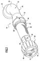
- eine perspektivische Darstellung des Luftstromreglers aus Figur 1 nach Art einer Explosionszeichnung;
- Figur 3:
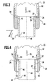
- eine Teilschnittansicht des Luftstromreglers aus Figur 2 mit einer Hülse in einer Schließstellung;
- Figur 4:
- eine Teilschnittansicht entsprechend Figur 3 mit der Hülse in ihrer Offenstellung;
- Figur 5:
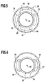
- eine Ansicht des Luftstromreglers in Richtung von Pfeil A aus Figur 3 mit der Hülse in ihrer Schließstellung und
- Figur 6:
- eine Ansicht entsprechend Figur 5 mit der Hülse in ihrer Offenstellung.
- In Figur 1 ist schematisch ein Staubsauger 10 dargestellt mit einem Sauggerät 11, an das eine Saugleitung in Form eines flexiblen Saugschlauches 12 angeschlossen ist. Der Saugschlauch 12 trägt an seinem freien Ende einen erfindungsgemäßen Luftstromregler 14, der ein Rohrstück 16 aufweist, auf den ein Schließteil in Form einer das Rohrstück 16 in Umfangsrichtung umgebenden Hülse 18 aufgesteckt ist. In den Figuren 1 und 2 ist die Hülse 18 nach Art einer Explosionszeichnung im Abstand zum Rohrstück 16 angeordnet, wohingegen in den Figuren 3 bis 6 der Luftstromregler 14 im montierten Zustand dargestellt ist.
- Das Rohrstück 16 umfasst einen vorderen Rohrabschnitt 20, an den eine in der Zeichnung nicht dargestellte, an sich bekannte Saugdüse angeschlossen werden kann, sowie einen hinteren Rohrabschnitt 22, der an seinem hinteren Ende ein Anschlussteil 23 aufweist zur Herstellung einer lösbaren Verbindung mit dem Saugschlauch 12.
- Der hintere Rohrabschnitt 22 ist gekrümmt und bildet einen Handgriff 24 aus, an dem der Benutzer den Luftstromregler 14 ergreifen kann.
- Der vordere Rohrabschnitt 22 verjüngt sich in Richtung auf dessen freies Ende 26 und kann in einen Rohrstutzen einer Saugdüse des Staubsaugers 10 eingesetzt werden.
- Das Rohrstück 16 definiert einen Saugkanal 30 und weist im Bereich zwischen dem vorderen Rohrabschnitt 20 und dem hinteren Rohrabschnitt 22 einen Erweiterungsabschnitt 32 auf, in dem sich der Strömungsquerschnitt des Saugkanals 30 über eine radial nach außen gerichtete Stufe 34 erweitert. In die Stufe 34 sind einander diametral gegenüberliegend zwei Falschluftöffnungen 36, 37 eingeformt. In axialem Abstand zur Stufe 34 ist außenseitig an den vorderen Rohrabschnitt 20 ein radial nach außen gerichteter Rastvorsprung 39 angeformt, der den vorderen Rohrabschnitt 20 in Umfangsrichtung vollständig umgibt.
- Die Hülse 18 umgreift in Höhe der Stufe 34 das Rohrstück 16 und weist innenseitig einen Bund 41 auf, der einerseits am Rastvorsprung 39 und andererseits an der Stufe 34 anliegt und daher die Hülse 18 in axialer Richtung festlegt.
- Innenseitig sind in die Hülse einander diametral gegenüberliegend zwei Ausnehmungen 43, 44 eingeformt, die jeweils einen Falschluftkanal ausbilden, indem sie einen Durchgang 46 bzw. 47 zwischen der Hülse 18 und der Außenseite des vorderen Rohrabschnittes 20 definieren.
- Die Hülse 18 ist um die Längsachse 49 des vorderen Rohrabschnitts 20 verdrehbar am Rohrstück 16 gehalten und kann zwischen einer ersten, in den Figuren 3 und 5 dargestellten Drehstellung und einer zweiten, in den Figuren 4 und 6 dargestellten Drehstellung kontinuierlich hin und her verdreht werden. In der ersten Drehstellung überdeckt der Bund 41 die Falschluftöffnungen 36 und 37, so dass über diese keine Falschluft von außen in den Saugkanal 30 eintreten kann. In der zweiten Drehstellung sind die Ausnehmungen 43 und 44 fluchtend zur Falschluftöffnung 36 bzw. 37 ausgerichtet, und folglich kann Falschluft parallel zur Strömungsrichtung 51 der den Saugkanal 30 durchströmenden Saugluft dem Saugkanal 30 zugeführt werden. Die Strömungsrichtung der Falschluft ist in Figur 4 durch die Pfeile 53 symbolisiert.
- Die Falschluft durchströmt somit sowohl die Ausnehmungen 43 und 44 der Hülse 18 als auch die Falschluftöffnungen 36 und 37 des Rohrstückes 16 parallel zur Strömungsrichtung 51 der Saugluft. Dies hat zur Folge, dass die Zuführung von Falschluft in den Saugkanal 30 ohne Umlenkungen erfolgen kann, und dies wiederum stellt sicher, dass die Zuführung von Falschluft ohne starke Geräuschentwicklung erfolgt.
Claims (10)
- Luftstromregler zum Regulieren des durch eine Saugdüse eines Staubsaugers hindurchströmenden Saugluftstromes, mit einem den Saugluftstrom aufnehmenden Saugkanal, dem über mindestens eine Falschluftöffnung Falschluft zuführbar ist, wobei die Falschluftöffnung mittels eines Schließteiles wahlweise freigebbar oder verschließbar ist, dadurch gekennzeichnet, dass die Falschluft dem Saugkanal (30) über die Falschluftöffnung (36, 37) parallel zur Strömungsrichtung (51) der Saugluft zuführbar ist.
- Luftstromregler nach Anspruch 1, dadurch gekennzeichnet, dass der Saugkanal (30) einen Erweiterungsabschnitt (32) aufweist, in dem sich der Strömungsquerschnitt des Saugkanals (30) erweitert, wobei die mindestens eine Falschluftöffnung (36, 37) im Erweiterungsabschnitt (32) angeordnet ist.
- Luftstromregler nach Anspruch 2, dadurch gekennzeichnet, dass der Erweitungsabschnitt (32) eine radial nach außen gerichtete Stufe (34) aufweist.
- Luftstromregler nach Anspruch 3, dadurch gekennzeichnet, dass in der Stufe (34) zumindest zwei, über den Umfang des Strömungskanals (30) gleichmäßig verteilte Falschluftöffnungen (36, 37) angeordnet sind.
- Luftstromregler nach einem der voranstehenden Ansprüche, dadurch gekennzeichnet, dass das Schließteil (18) zumindest einen Falschluftkanal (43, 44) aufweist, der wahlweise fluchtend oder versetzt zur Falschluftöffnung (36, 37) positionierbar ist, wobei Falschluft parallel zur Strömungsrichtung (51) der Saugluft über den Falschluftkanal (43, 44) der Falschluftöffnung (36, 37) zuführbar ist.
- Luftstromregler nach einem der voranstehenden Ansprüche, dadurch gekennzeichnet, dass der Luftstromregler (14) ein Rohrstück (16) umfasst, das den Saugkanal (30) ausbildet, und dass das Schließteil als das Rohrstück (16) in Höhe der mindestens einen Falschluftöffnung (36, 37) umgreifende Hülse (18) ausgebildet ist, die relativ zum Rohrstück (16) verdrehbar ist, wobei die Falschluft über mindestens einen sich parallel zur Strömungsrichtung (51) der Saugluft erstreckenden Durchgang (46, 47) der Falschluftöffnung (36, 37) zuführbar und die Falschluftöffnung (36, 37) mittels der Hülse (18) wahlweise freigebbar oder verschließbar ist.
- Luftstromregler nach Anspruch 6, dadurch gekennzeichnet, dass der Durchgang als in die Hülse (18) eingeformte Ausnehmung (43, 44) ausgestaltet ist, die einen wahlweise fluchtend oder versetzt zu einer Falschluftöffnung (36, 37) ausrichtbaren Falschluftkanal ausbildet, über den die Falschluft parallel zur Strömungsrichtung (51) der Saugluft der Falschluftöffnung (36, 37) zuführbar ist.
- Luftstromregler nach Anspruch 6 oder 7, dadurch gekennzeichnet, dass die Hülse (18) axial unverschieblich am Rohrstück (16) gehalten ist.
- Luftstromregler nach Anspruch 6, 7 oder 8, dadurch gekennzeichnet, dass die Hülse (18) mit dem Rohrstück (16) verrastbar ist.
- Luftstromregler nach einem der Ansprüche 6 bis 9, dadurch gekennzeichnet, dass das Rohrstück (16) gekrümmt ist.
Applications Claiming Priority (1)
| Application Number | Priority Date | Filing Date | Title |
|---|---|---|---|
| DE102005010983A DE102005010983B3 (de) | 2005-03-03 | 2005-03-03 | Luftstromregler für Staubsauger |
Publications (3)
| Publication Number | Publication Date |
|---|---|
| EP1698261A2 true EP1698261A2 (de) | 2006-09-06 |
| EP1698261A3 EP1698261A3 (de) | 2007-11-28 |
| EP1698261B1 EP1698261B1 (de) | 2009-04-15 |
Family
ID=36079337
Family Applications (1)
| Application Number | Title | Priority Date | Filing Date |
|---|---|---|---|
| EP06000981A Expired - Lifetime EP1698261B1 (de) | 2005-03-03 | 2006-01-18 | Luftstromregler für Staubsauger |
Country Status (4)
| Country | Link |
|---|---|
| EP (1) | EP1698261B1 (de) |
| AT (1) | ATE428342T1 (de) |
| DE (1) | DE102005010983B3 (de) |
| DK (1) | DK1698261T3 (de) |
Cited By (2)
| Publication number | Priority date | Publication date | Assignee | Title |
|---|---|---|---|---|
| EP2123204A3 (de) * | 2008-05-21 | 2012-07-04 | Sprintus GmbH | Vorrichtung zur Regulierung des Saugluftstroms eines Saugers |
| CN113729547A (zh) * | 2020-05-29 | 2021-12-03 | 优联沃森(苏州)智能技术有限公司 | 一种恒压式家用清洁吸尘器 |
Families Citing this family (1)
| Publication number | Priority date | Publication date | Assignee | Title |
|---|---|---|---|---|
| DE102022121289A1 (de) * | 2022-08-23 | 2024-02-29 | Hawig Maschinenfabrik Gesellschaft mit beschränkter Haftung | Adaptervorrichtung für eine Saugvorrichtung und Reinigungsanordnung |
Family Cites Families (3)
| Publication number | Priority date | Publication date | Assignee | Title |
|---|---|---|---|---|
| DE1795837U (de) * | 1959-07-07 | 1959-09-17 | Fritz Mueller Coroplast K G | Vorrichtung zur regelung des unterdrukkes im saugrohr von staubsaugern. |
| US4961245A (en) * | 1990-02-05 | 1990-10-09 | Ryobi Motor Products Corp. | Suction controlling arrangement in a canister vacuum cleaner |
| ITMI20040471A1 (it) * | 2004-03-12 | 2004-06-12 | Guido Valentini | Dispositivo per la regolazione del flusso di aspirazione in un tubo flessibile di collegamento tra un utensile per la lavorazione di superfici ed un gruppo dio aspirazione delle polveri di lavorazione |
-
2005
- 2005-03-03 DE DE102005010983A patent/DE102005010983B3/de not_active Expired - Fee Related
-
2006
- 2006-01-18 AT AT06000981T patent/ATE428342T1/de not_active IP Right Cessation
- 2006-01-18 EP EP06000981A patent/EP1698261B1/de not_active Expired - Lifetime
- 2006-01-18 DK DK06000981T patent/DK1698261T3/da active
Cited By (2)
| Publication number | Priority date | Publication date | Assignee | Title |
|---|---|---|---|---|
| EP2123204A3 (de) * | 2008-05-21 | 2012-07-04 | Sprintus GmbH | Vorrichtung zur Regulierung des Saugluftstroms eines Saugers |
| CN113729547A (zh) * | 2020-05-29 | 2021-12-03 | 优联沃森(苏州)智能技术有限公司 | 一种恒压式家用清洁吸尘器 |
Also Published As
| Publication number | Publication date |
|---|---|
| ATE428342T1 (de) | 2009-05-15 |
| DK1698261T3 (da) | 2009-06-22 |
| EP1698261A3 (de) | 2007-11-28 |
| DE102005010983B3 (de) | 2006-08-31 |
| EP1698261B1 (de) | 2009-04-15 |
Similar Documents
| Publication | Publication Date | Title |
|---|---|---|
| DE19843973B4 (de) | Schlauchanordnung für einen Staubsauger | |
| DE60225837T2 (de) | Reinigungskopf für staubsauger | |
| DE102008052277B3 (de) | Spenderventilanordnung für ein Gefäß | |
| EP1844691B1 (de) | Vorrichtung zum lösbaren Befestigen eines Staubfilterbeutels in einem staubsaugenden Gerät | |
| EP2866631B1 (de) | Kombination aus einem kleinsauger und einem staubsaugergehäuse sowie kleinsauger und staubsaugergehäuse | |
| WO2014001492A1 (de) | Kombination aus einem kleinsauger und einem stielsaugerrahmen um einen stielsauger | |
| EP0526694A1 (de) | Aktive Staubsaugerdüse | |
| WO2017017286A2 (de) | Pneumatische reinigungspistole | |
| DE19630286A1 (de) | Handstaubsauger mit einem Griffrohr | |
| DE60200858T2 (de) | Umwandelbare Austritttöffnung für Staubsauger | |
| DE1475706A1 (de) | Rohrfoermiges Verbindungsaggregat | |
| EP1698261B1 (de) | Luftstromregler für Staubsauger | |
| EP2866632B1 (de) | Kombination aus einem kleinsauger und einem stielsaugerrahmen sowie kleinsauger und stielsaugerrahmen | |
| DE2555068A1 (de) | Kuerette | |
| EP0688528B1 (de) | Staubsaugermundstück mit Stützrädern | |
| DE9420324U1 (de) | Luftkopf | |
| EP2198764B1 (de) | Nebenlufteinrichtung für einen Staubsauger | |
| DE102016100820A1 (de) | Saugreinigungsgerät | |
| EP2987434B1 (de) | Milcherwärmungs- und/oder milchaufschäumvorrichtung sowie getränkezubereitungsvorrichtung | |
| DE102007011320B4 (de) | Fluidische Steckkupplungsvorrichtung | |
| DE19851405C2 (de) | Zusatzvorrichtung für statische Staubsaugerdüsen | |
| DE29500994U1 (de) | Staubsauger | |
| DE102009048852A1 (de) | Saugdüse für ein Saugaggregat oder einstellbares Filtrierungselement | |
| DE10246675B4 (de) | Staubsauger mit einer Gebläsevorrichtung, einem Staubraum, einer Bodendüse und einem Saugschlauch | |
| DE29825237U1 (de) | Schlauchanordnung für einen Staubsauger |
Legal Events
| Date | Code | Title | Description |
|---|---|---|---|
| PUAI | Public reference made under article 153(3) epc to a published international application that has entered the european phase |
Free format text: ORIGINAL CODE: 0009012 |
|
| AK | Designated contracting states |
Kind code of ref document: A2 Designated state(s): AT BE BG CH CY CZ DE DK EE ES FI FR GB GR HU IE IS IT LI LT LU LV MC NL PL PT RO SE SI SK TR |
|
| AX | Request for extension of the european patent |
Extension state: AL BA HR MK YU |
|
| PUAL | Search report despatched |
Free format text: ORIGINAL CODE: 0009013 |
|
| AK | Designated contracting states |
Kind code of ref document: A3 Designated state(s): AT BE BG CH CY CZ DE DK EE ES FI FR GB GR HU IE IS IT LI LT LU LV MC NL PL PT RO SE SI SK TR |
|
| AX | Request for extension of the european patent |
Extension state: AL BA HR MK YU |
|
| 17P | Request for examination filed |
Effective date: 20080212 |
|
| 17Q | First examination report despatched |
Effective date: 20080314 |
|
| AKX | Designation fees paid |
Designated state(s): AT BE BG CH CY CZ DE DK EE ES FI FR GB GR HU IE IS IT LI LT LU LV MC NL PL PT RO SE SI SK TR |
|
| GRAP | Despatch of communication of intention to grant a patent |
Free format text: ORIGINAL CODE: EPIDOSNIGR1 |
|
| GRAP | Despatch of communication of intention to grant a patent |
Free format text: ORIGINAL CODE: EPIDOSNIGR1 |
|
| GRAS | Grant fee paid |
Free format text: ORIGINAL CODE: EPIDOSNIGR3 |
|
| GRAA | (expected) grant |
Free format text: ORIGINAL CODE: 0009210 |
|
| AK | Designated contracting states |
Kind code of ref document: B1 Designated state(s): AT BE BG CH CY CZ DK EE ES FI FR GB GR HU IE IS IT LI LT LU LV MC NL PL PT RO SE SI SK TR |
|
| REG | Reference to a national code |
Ref country code: CH Ref legal event code: NV Representative=s name: ISLER & PEDRAZZINI AG Ref country code: CH Ref legal event code: EP Ref country code: GB Ref legal event code: FG4D Free format text: NOT ENGLISH |
|
| REG | Reference to a national code |
Ref country code: RO Ref legal event code: EPE |
|
| REG | Reference to a national code |
Ref country code: IE Ref legal event code: FG4D |
|
| REG | Reference to a national code |
Ref country code: DK Ref legal event code: T3 |
|
| REG | Reference to a national code |
Ref country code: SE Ref legal event code: TRGR |
|
| PG25 | Lapsed in a contracting state [announced via postgrant information from national office to epo] |
Ref country code: LT Free format text: LAPSE BECAUSE OF FAILURE TO SUBMIT A TRANSLATION OF THE DESCRIPTION OR TO PAY THE FEE WITHIN THE PRESCRIBED TIME-LIMIT Effective date: 20090415 Ref country code: ES Free format text: LAPSE BECAUSE OF FAILURE TO SUBMIT A TRANSLATION OF THE DESCRIPTION OR TO PAY THE FEE WITHIN THE PRESCRIBED TIME-LIMIT Effective date: 20090726 Ref country code: FI Free format text: LAPSE BECAUSE OF FAILURE TO SUBMIT A TRANSLATION OF THE DESCRIPTION OR TO PAY THE FEE WITHIN THE PRESCRIBED TIME-LIMIT Effective date: 20090415 Ref country code: PT Free format text: LAPSE BECAUSE OF FAILURE TO SUBMIT A TRANSLATION OF THE DESCRIPTION OR TO PAY THE FEE WITHIN THE PRESCRIBED TIME-LIMIT Effective date: 20090915 |
|
| PG25 | Lapsed in a contracting state [announced via postgrant information from national office to epo] |
Ref country code: LV Free format text: LAPSE BECAUSE OF FAILURE TO SUBMIT A TRANSLATION OF THE DESCRIPTION OR TO PAY THE FEE WITHIN THE PRESCRIBED TIME-LIMIT Effective date: 20090415 Ref country code: SI Free format text: LAPSE BECAUSE OF FAILURE TO SUBMIT A TRANSLATION OF THE DESCRIPTION OR TO PAY THE FEE WITHIN THE PRESCRIBED TIME-LIMIT Effective date: 20090415 Ref country code: PL Free format text: LAPSE BECAUSE OF FAILURE TO SUBMIT A TRANSLATION OF THE DESCRIPTION OR TO PAY THE FEE WITHIN THE PRESCRIBED TIME-LIMIT Effective date: 20090415 Ref country code: IS Free format text: LAPSE BECAUSE OF FAILURE TO SUBMIT A TRANSLATION OF THE DESCRIPTION OR TO PAY THE FEE WITHIN THE PRESCRIBED TIME-LIMIT Effective date: 20090815 |
|
| REG | Reference to a national code |
Ref country code: IE Ref legal event code: FD4D |
|
| PG25 | Lapsed in a contracting state [announced via postgrant information from national office to epo] |
Ref country code: EE Free format text: LAPSE BECAUSE OF FAILURE TO SUBMIT A TRANSLATION OF THE DESCRIPTION OR TO PAY THE FEE WITHIN THE PRESCRIBED TIME-LIMIT Effective date: 20090415 Ref country code: IE Free format text: LAPSE BECAUSE OF FAILURE TO SUBMIT A TRANSLATION OF THE DESCRIPTION OR TO PAY THE FEE WITHIN THE PRESCRIBED TIME-LIMIT Effective date: 20090415 |
|
| PLBE | No opposition filed within time limit |
Free format text: ORIGINAL CODE: 0009261 |
|
| STAA | Information on the status of an ep patent application or granted ep patent |
Free format text: STATUS: NO OPPOSITION FILED WITHIN TIME LIMIT |
|
| PG25 | Lapsed in a contracting state [announced via postgrant information from national office to epo] |
Ref country code: SK Free format text: LAPSE BECAUSE OF FAILURE TO SUBMIT A TRANSLATION OF THE DESCRIPTION OR TO PAY THE FEE WITHIN THE PRESCRIBED TIME-LIMIT Effective date: 20090415 |
|
| REG | Reference to a national code |
Ref country code: HU Ref legal event code: AG4A Ref document number: E006612 Country of ref document: HU |
|
| 26N | No opposition filed |
Effective date: 20100118 |
|
| PG25 | Lapsed in a contracting state [announced via postgrant information from national office to epo] |
Ref country code: BG Free format text: LAPSE BECAUSE OF FAILURE TO SUBMIT A TRANSLATION OF THE DESCRIPTION OR TO PAY THE FEE WITHIN THE PRESCRIBED TIME-LIMIT Effective date: 20090715 |
|
| PG25 | Lapsed in a contracting state [announced via postgrant information from national office to epo] |
Ref country code: MC Free format text: LAPSE BECAUSE OF NON-PAYMENT OF DUE FEES Effective date: 20100131 |
|
| PG25 | Lapsed in a contracting state [announced via postgrant information from national office to epo] |
Ref country code: GR Free format text: LAPSE BECAUSE OF FAILURE TO SUBMIT A TRANSLATION OF THE DESCRIPTION OR TO PAY THE FEE WITHIN THE PRESCRIBED TIME-LIMIT Effective date: 20090716 |
|
| REG | Reference to a national code |
Ref country code: AT Ref legal event code: MM01 Ref document number: 428342 Country of ref document: AT Kind code of ref document: T Effective date: 20110118 |
|
| PG25 | Lapsed in a contracting state [announced via postgrant information from national office to epo] |
Ref country code: CY Free format text: LAPSE BECAUSE OF FAILURE TO SUBMIT A TRANSLATION OF THE DESCRIPTION OR TO PAY THE FEE WITHIN THE PRESCRIBED TIME-LIMIT Effective date: 20090415 |
|
| REG | Reference to a national code |
Ref country code: DE Ref legal event code: R108 |
|
| PG25 | Lapsed in a contracting state [announced via postgrant information from national office to epo] |
Ref country code: LU Free format text: LAPSE BECAUSE OF NON-PAYMENT OF DUE FEES Effective date: 20100118 |
|
| REG | Reference to a national code |
Ref country code: DE Ref legal event code: R108 Effective date: 20120912 |
|
| PG25 | Lapsed in a contracting state [announced via postgrant information from national office to epo] |
Ref country code: AT Free format text: LAPSE BECAUSE OF NON-PAYMENT OF DUE FEES Effective date: 20110118 |
|
| REG | Reference to a national code |
Ref country code: FR Ref legal event code: PLFP Year of fee payment: 11 |
|
| PGFP | Annual fee paid to national office [announced via postgrant information from national office to epo] |
Ref country code: RO Payment date: 20151208 Year of fee payment: 11 Ref country code: FR Payment date: 20151208 Year of fee payment: 11 |
|
| PGFP | Annual fee paid to national office [announced via postgrant information from national office to epo] |
Ref country code: NL Payment date: 20160111 Year of fee payment: 11 |
|
| PGFP | Annual fee paid to national office [announced via postgrant information from national office to epo] |
Ref country code: CZ Payment date: 20160105 Year of fee payment: 11 Ref country code: CH Payment date: 20160111 Year of fee payment: 11 Ref country code: TR Payment date: 20160108 Year of fee payment: 11 |
|
| PGFP | Annual fee paid to national office [announced via postgrant information from national office to epo] |
Ref country code: SE Payment date: 20160112 Year of fee payment: 11 Ref country code: HU Payment date: 20151216 Year of fee payment: 11 Ref country code: GB Payment date: 20160113 Year of fee payment: 11 Ref country code: BE Payment date: 20151223 Year of fee payment: 11 |
|
| PG25 | Lapsed in a contracting state [announced via postgrant information from national office to epo] |
Ref country code: BE Free format text: LAPSE BECAUSE OF NON-PAYMENT OF DUE FEES Effective date: 20170131 |
|
| REG | Reference to a national code |
Ref country code: CH Ref legal event code: PL |
|
| REG | Reference to a national code |
Ref country code: NL Ref legal event code: MM Effective date: 20170201 |
|
| GBPC | Gb: european patent ceased through non-payment of renewal fee |
Effective date: 20170118 |
|
| REG | Reference to a national code |
Ref country code: FR Ref legal event code: ST Effective date: 20170929 |
|
| PG25 | Lapsed in a contracting state [announced via postgrant information from national office to epo] |
Ref country code: FR Free format text: LAPSE BECAUSE OF NON-PAYMENT OF DUE FEES Effective date: 20170131 Ref country code: CH Free format text: LAPSE BECAUSE OF NON-PAYMENT OF DUE FEES Effective date: 20170131 Ref country code: CZ Free format text: LAPSE BECAUSE OF NON-PAYMENT OF DUE FEES Effective date: 20170118 Ref country code: RO Free format text: LAPSE BECAUSE OF NON-PAYMENT OF DUE FEES Effective date: 20170118 Ref country code: LI Free format text: LAPSE BECAUSE OF NON-PAYMENT OF DUE FEES Effective date: 20170131 |
|
| PG25 | Lapsed in a contracting state [announced via postgrant information from national office to epo] |
Ref country code: GB Free format text: LAPSE BECAUSE OF NON-PAYMENT OF DUE FEES Effective date: 20170118 Ref country code: SE Free format text: LAPSE BECAUSE OF NON-PAYMENT OF DUE FEES Effective date: 20170119 Ref country code: NL Free format text: LAPSE BECAUSE OF NON-PAYMENT OF DUE FEES Effective date: 20170201 Ref country code: HU Free format text: LAPSE BECAUSE OF NON-PAYMENT OF DUE FEES Effective date: 20170119 |
|
| REG | Reference to a national code |
Ref country code: BE Ref legal event code: MM Effective date: 20170131 |
|
| PGFP | Annual fee paid to national office [announced via postgrant information from national office to epo] |
Ref country code: IT Payment date: 20190121 Year of fee payment: 14 |
|
| PGFP | Annual fee paid to national office [announced via postgrant information from national office to epo] |
Ref country code: DK Payment date: 20190110 Year of fee payment: 14 |
|
| REG | Reference to a national code |
Ref country code: DK Ref legal event code: EBP Effective date: 20200131 |
|
| PG25 | Lapsed in a contracting state [announced via postgrant information from national office to epo] |
Ref country code: DK Free format text: LAPSE BECAUSE OF NON-PAYMENT OF DUE FEES Effective date: 20200131 Ref country code: IT Free format text: LAPSE BECAUSE OF NON-PAYMENT OF DUE FEES Effective date: 20200118 |
|
| PG25 | Lapsed in a contracting state [announced via postgrant information from national office to epo] |
Ref country code: TR Free format text: LAPSE BECAUSE OF NON-PAYMENT OF DUE FEES Effective date: 20170118 |