EP1696167B1 - Als Fertigbauteil ausgebildetes Dämmstoffelement zur Aufnahme eines Schornsteinrohres oder dergleichen - Google Patents
Als Fertigbauteil ausgebildetes Dämmstoffelement zur Aufnahme eines Schornsteinrohres oder dergleichen Download PDFInfo
- Publication number
- EP1696167B1 EP1696167B1 EP06003485A EP06003485A EP1696167B1 EP 1696167 B1 EP1696167 B1 EP 1696167B1 EP 06003485 A EP06003485 A EP 06003485A EP 06003485 A EP06003485 A EP 06003485A EP 1696167 B1 EP1696167 B1 EP 1696167B1
- Authority
- EP
- European Patent Office
- Prior art keywords
- insulating element
- insulating
- element according
- core
- core element
- Prior art date
- Legal status (The legal status is an assumption and is not a legal conclusion. Google has not performed a legal analysis and makes no representation as to the accuracy of the status listed.)
- Expired - Lifetime
Links
Images

Classifications
-
- F—MECHANICAL ENGINEERING; LIGHTING; HEATING; WEAPONS; BLASTING
- F16—ENGINEERING ELEMENTS AND UNITS; GENERAL MEASURES FOR PRODUCING AND MAINTAINING EFFECTIVE FUNCTIONING OF MACHINES OR INSTALLATIONS; THERMAL INSULATION IN GENERAL
- F16L—PIPES; JOINTS OR FITTINGS FOR PIPES; SUPPORTS FOR PIPES, CABLES OR PROTECTIVE TUBING; MEANS FOR THERMAL INSULATION IN GENERAL
- F16L59/00—Thermal insulation in general
- F16L59/02—Shape or form of insulating materials, with or without coverings integral with the insulating materials
- F16L59/021—Shape or form of insulating materials, with or without coverings integral with the insulating materials comprising a single piece or sleeve, e.g. split sleeves; consisting of two half sleeves; comprising more than two segments
- F16L59/024—Shape or form of insulating materials, with or without coverings integral with the insulating materials comprising a single piece or sleeve, e.g. split sleeves; consisting of two half sleeves; comprising more than two segments consisting of two half sleeves
-
- E—FIXED CONSTRUCTIONS
- E04—BUILDING
- E04F—FINISHING WORK ON BUILDINGS, e.g. STAIRS, FLOORS
- E04F17/00—Vertical ducts; Channels, e.g. for drainage
- E04F17/02—Vertical ducts; Channels, e.g. for drainage for carrying away waste gases, e.g. flue gases; Building elements specially designed therefor, e.g. shaped bricks or sets thereof
Definitions
- the invention relates to a trained as prefabricated component insulating element according to the preamble of claim 1.
- Such an insulating element is made FR-2 588 595 known.
- masonry openings can already be provided in the planning of buildings, which is irrelevant, whether it is a new building, a renovation or the like.
- the cross section of the masonry opening is typically larger in size than the cross section of the chimney pipe. If a laying of the chimney pipe is not required immediately, there is a need to close the masonry opening. The choice of suitable means is usually left to the craftsman on site. Above all, there is the disadvantage that in later implementation of a chimney pipe, the entire masonry opening closure must be removed.
- the object of the invention is to provide an insulating element ready, which can be used as a prefabricated part in a masonry opening and the inclusion of a chimney pipe with a fixed diameter, even at a later date, allows.
- a core element is provided within the insulating element, which is removably or removably received within the insulating element.
- a receiving opening is created suitable for a chimney pipe with a fixed diameter.
- the insulating element is designed for the laying of chimney pipes with a fixed diameter. Due to the block-like design of the insulating element, it can be easily laid in appropriate masonry breakthroughs. The addition of cotton wool is therefore no longer necessary. Due to the fact that the insulating element is guaranteed as a prefabricated element, consistent conditions with regard to insulating properties and the like are ensured over the entire insulating element, ie. H.
- the properties of the insulating element can no longer be influenced by the craftsman, as is the case with the manually introduced stuffing wool.
- the core element is arranged centrally, so that the receiving opening for the chimney pipe is centered. This can be ensured in a simple manner that, for example, the chimney pipe each centrally located within the insulating element and thus accurately positioned within the suitably prepared masonry opening.
- the core element fills the insulating element substantially up to the minimally kept separating cut completely.
- the chimney pipe can then be laid over this insulating element at a later date.
- the coating is expediently added to the surface-side boundary layer, for example by precipitation. This results in a good adhesion for a plaster job.
- the insulating elements are provided with receiving openings whose diameter is adapted to the standard diameters of the chimney pipes.
- the insulating elements on receiving openings with a diameter of 130, 150 and 180 mm.
- the receiving opening is circular according to the usual construction of the chimney pipes, but it is also within the scope of the invention if necessary to perform the receiving opening corresponding oval or square, if this chimney pipe side appropriate requirements are to be met, so they are present with a non-circular cross-section.
- the insulating element is formed as a monobloc, so that the core element is machined out of the solid, for example, by introducing separating cuts, what about a thin band saw or the like can be used.
- the circumferential separating cut to form the core element is not guided completely over the circumference, but at least one comparatively narrow separating cut zone remains in the manner of a holding web, so that the core element is kept transport secured, so to speak. It then requires for use only corresponding small cuts, which can be made readily on site by the craftsman with the help of about a knife.
- the insulating element is centered and divided into two insulating element halves or blank halves, wherein the core element in the form of two core element halves is formed, which are respectively received or arranged in the insulating element halves. After assembling the two insulating element halves to the insulating element, the core element halves complement each other to the core element.
- the core element halves can be transported fixed by a holding web, wherein an arrangement of the holding web on the contact surface of the two blank halves is preferred by the separating cut to a desired web width, i. is realized in an opening angle ⁇ 180 °.
- the section to be cut is made clear by corresponding marking lines.
- optical marking lines can be used, which can be produced for example in a simple manner by hot air nozzles or paint application.
- the material used is rock wool for the insulating material. But it is particularly suitable mineral wool, which is soluble in a physiological milieu.
- a suitable composition for this is as follows: SiO 2 39 - 55% preferably 40 - 52% Al 2 O 3 16 - 27% preferably 16 - 26% CaO 9.5 - 20% preferably 10 - 18% MgO 1 - 5% preferably 1 - 4.9% Na 2 O 0 - 15% preferably 2 - 12% K 2 O 0 - 15% preferably 2 - 12% R 2 O (Na 2 O + K 2 O) 10 - 14.7% preferably 10 - 13.5% P 2 O 5 0 - 3% especially 0 - 2% Fe 2 O 3 (total iron) 1.5 - 15% especially 3.2 - 8% B 2 O 3 0 - 2% preferably 0 - 1% TiO 2 0 - 2% preferably 0.4 - 1% miscellaneous 0 - 2.0%
- the composition of the mineral fibers has an alkali / alkaline earth mass ratio ⁇ 1 and the fiber structure of the Dämmelements is determined by a mean geometric fiber diameter ⁇ 4 microns.
- the bulk density of the insulating elements is suitably in the range of 60 kg / m 3 to 140 kg / m 3 and is in particular ⁇ 80 kg / m 3 .
- the invention further relates to a system for the insulation of chimney pipe passages through openings or openings in walls, ceiling or other masonry or compartments using a block-like insulating element to fill the openings or openings and for receiving a chimney pipe, wherein the insulating element according to the features of claims 1 to 15 may be formed.
- the insulation element according to the invention also allows a sound insulation of the chimney pipe from the rest of the building, in particular low-frequency vibrations are prevented from spreading in the adjacent to an insulating element masonry - or Gefachmaschine wherein the insulating element according to features of claims 1 to 15 may be formed
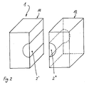
- FIGS. 1 and 2 show perspective views of various embodiments of the insulating element.
- 1 is a block-shaped insulating material shown, which is designed in the illustrated embodiment as a cuboid with a rectangular cross section and that by way of example with a length and width of 600 mm and a depth of 240 mm.
- This insulating element 1 is used to hold a chimney pipe with a fixed diameter, which in an opening of masonry or Gefaches, in particular a wall, floor slab or floor is to be arranged.
- chimney pipes are formed from sheet metal.
- the insulating element 1 is formed with a core element 2 formed in the interior.
- This core element 2 is disposed within the insulating element 1 and extends, as shown in phantom, from the front main surface 3 continuously to the rear main surface 5 and back 5.
- the core element 2 thus forms a cylindrical body extending from the front main surface 3 to the rear main surface 5 extends continuously and has a circular cross section, more specifically, the core element 2 is formed as a solid cylinder with a typically circular cross-section.
- the cylinder is produced by a separating cut of the full material of the cuboid insulating element 1 and by, for example, a band saw. This is introduced, for example, from the upper main surface 4, wherein the section extends from there to the material of the fully cylindrical core element 2. From here, the separating cut is guided over the circumference, whereby the fully cylindrical core element 2 is formed by material separation. It goes without saying that the cuts are performed gently and with the smallest possible separation gap.
- these trennitesEF holding webs have only holding function and extend circumferentially only over a length of about 10 to 20 mm. By this holding webs otherwise fully separated core element 2 adheres to the fuse on the transport path in the insulating element 1 and thus can not fall out during transport.
- a full-length retaining web advantageously arranged axially centrally in the insulating element, can be realized with a small axial extent.
- a continuous joint formation is advantageously prevented.
- the core element 2 defines a receiving opening 6 within the insulating element, wherein the outer contour of the core element corresponds to the inner contour of the insulating element.
- the separating cut can be made over the entire circumference of the core element, so that the core element is removably seated in the insulating element. Since the separation cut is made with a very thin band saw blade, which works out only a small amount of material, there remains only a minimal separation column, which may expediently be a size ⁇ 1 mm.
- insulating element 1 is a prefabricated component in monobloc construction, the core element can be made with only one separating section of the main surface 6 ago. As can be seen, the insulating element 1 can be used as a block in a corresponding opening wall opening without plugging stuffed wool would be required.
- the insulating element is composed of two separate core element halves or blank halves 11 and 12, which are formed almost identical and composed the insulating element 1 form.
- This insulating element 1 also has a core element 2, which, however, is composed of two core element halves 2 'and 2 ".
- the core element halves 2' and 2" are each arranged or formed in the corresponding blank halves 11 and 12, respectively.
- This embodiment has manufacturing advantages, as a result of the split version of the insulating element in two insulating element halves, the core element can be easier to work out what again done by appropriate cut. For transport, it is possible to foster the two insulating halves by a foil tape or the like. To the block-like insulating element together.
- a transport safety can take place in that in the same manner as in the embodiment according to FIG. 1 corresponding holding webs remain in the separating cut region of the core element halves, such as at the interface of the two blank halves, on which they are assembled.
- the corresponding core element can be easily removed and after assembling the two blank halves, the insulating element can be easily mounted in a wall opening.
- the illustrated embodiments of the insulating element are designed to a depth of 240 mm, so that it can be installed in walls with conventional thicknesses.
- the invention is not fixed to this depth, but the insulating element can be made with other dimensions in terms of depth, length and width. If larger wall thicknesses are to be bridged, it is also possible for a plurality of insulating elements to be inserted in a modular manner in succession into an opening in the aperture.
- the insulating element 1 which is to be heat resistant, rockwool is suitable.
- rockwool is suitable.
- heat-resistant mineral wool with biosoluble properties is useful.
- the embodiments of the insulating element shown in the figures have a density of 100 kg / m 3 and the binder content (dry) is 2.5%. Such an insulating element thus meets the requirements of fire protection class F90 (according to DIN standard).
Landscapes
- Engineering & Computer Science (AREA)
- General Engineering & Computer Science (AREA)
- Architecture (AREA)
- Mechanical Engineering (AREA)
- Civil Engineering (AREA)
- Structural Engineering (AREA)
- Building Environments (AREA)
- Thermal Insulation (AREA)
- Insulators (AREA)
- Investigating Or Analyzing Materials By The Use Of Electric Means (AREA)
- Laminated Bodies (AREA)
Description
- Die Erfindung betrifft ein als Fertigbauteil ausgebildetes Dämmstoffelement gemäß dem Oberbegriff des Patentanspruches 1.
- Ein solches Dämmstoffelement ist aus
FR-2 588 595 - Für die Durchführung von Schornsteinrohren aus Stahlblech, aber auch aus anderen Materialien, etwa Schamotte, durch Mauerwerk oder Gefache, wie Wänden, Geschossdecken und dergleichen können bereits bei der Gebäudeplanung Mauerwerksöffnungen vorgesehen werden, wobei unerheblich ist, ob es sich um einen Neubau, eine Sanierung oder dergleichen handelt. Der Querschnitt der Mauerwerksöffnung ist typischerweise größer dimensioniert als der Querschnitt des Schornsteinrohres. Falls eine Verlegung des Schornsteinrohres nicht sofort erforderlich ist, ergibt sich die Notwendigkeit die Mauerwerksöffnung zu verschließen. Die Wahl geeigneter Mittel bleibt meist dem Handwerker vor Ort überlassen. Vor allem ergibt sich der Nachteil, dass bei späterer Durchführung eines Schornsteinrohres der gesamte Mauerwerksöffnungsverschluss entfernt werden muss. Der Zwischenraum zwischen dem Außenumfang des Schornsteinrohres und der Mauerwerksöffnung wird dann üblicherweise mit Stopfwolle aus Mineralwolle gefüllt, um das Schornsteinrohr in der gewünschten Ausrichtung in der Mauerwerksöffnung zu fixieren und eine entsprechende Abdichtung herbeizuführen. Je nach Ausführung durch den Handwerker wird hierbei eine mehr oder weniger vollständige Füllung und damit ausreichende Dämmung erzielt. Als Gesamtnachteil dieses Vorgehens ergibt sich eine aufwändige und umständliche Vorgehensweise.
- Aufgabe der Erfindung ist es, ein Dämmstoffelement bereit zu stellen, welches als Fertigteil ausgebildet in eine Mauerwerksöffnung eingesetzt werden kann und die Aufnahme eines Schornsteinrohres mit fixem Durchmesser, auch zu einem späteren Zeitpunkt, ermöglicht.
- Diese Aufgabe wird erfindungsgemäß durch die im kennzeichnenden Teil des Anspruches 1 enthaltenen Merkmale gelöst, wobei zweckmäßige Weiterbildungen der Erfindung durch die in den Unteransprüchen enthaltenen Merkmale gekennzeichnet sind.
- Nach Maßgabe der Erfindung ist innerhalb des Dämmstoffelementes ein Kernelement vorgesehen, das herausnehmbar oder heraustrennbar innerhalb des Dämmstoffelementes aufgenommen ist. Bei Herausnahme des Kernelementes wird eine Aufnahmeöffnung passend für ein Schornsteinrohr mit einem fixen Durchmesser geschaffen. Dadurch ist das Dämmstoffelement für das Verlegen von Schornsteinrohren mit einem fixen Durchmesser ausgelegt. Infolge der blockartigen Ausbildung des Dämmstoffelementes kann es mühelos in entsprechenden Mauerwerksdurchbrüchen verlegt werden. Die Beigabe von Stopfwolle ist damit nicht mehr erforderlich. Dadurch, dass das Dämmstoffelement als Fertigbauelement gewährleistet ist, werden gleichbleibende Bedingungen bezüglich Dämmfähigkeit und dergleichen über das gesamte Dämmstoffelement sichergestellt, d. h. die Eigenschaften des Dämmstoffelementes können vom Handwerker nicht mehr beeinflusst werden, wie es im Falle der manuell eingebrachten Stopfwolle gegeben ist. Zweckmäßigerweise ist das Kernelement mittig angeordnet, so dass auch die Aufnahmeöffnung für das Schornsteinrohr mittig ist. Damit kann in einfacher Weise sichergestellt werden, dass beispielsweise das Schornsteinrohr jeweils zentral innerhalb des Dämmstoffelementes angeordnet und somit auch innerhalb der geeignet aufbereiteten Mauerwerksöffnung exakt positioniert ist.
- Zweckmäßigerweise füllt das Kernelement das Dämmstoffelement im Wesentlichen bis auf den minimal gehaltenen Trennschnitt vollständig aus. Wie bereits dargelegt ist es zweckmäßig, das Dämmstoffelement mit dem Kernelement zur Verfügung zu stellen, um das Dämmstoffelement in bereits vorgefertigten Mauerwerksdurchbrüchen für spätere Verwendungszwecke einsetzen zu können, um für eine ausreichende Wärmedämmung des Bauwerkes zu sorgen und um zu verhindern, dass Kältebrücken entstehen können. Bei Bedarf kann dann zu einem späteren Zeitpunkt das Schornsteinrohr über dieses Dämmstoffelement verlegt werden. Insbesondere in diesem Zusammenhang ist es zweckmäßig, entsprechende Stirnflächen des Dämmstoffelementes mit einer putzaffinen Trägerschicht zu beschichten, etwa mit Wasserglas. Die Beschichtung wird zweckmäßigerweise in die oberflächenseitige Grenzschicht eingetragen, etwa eingewalkt. Dadurch ergibt sich eine gute Haftung für einen Putzauftrag.
- Zweckmäßigerweise werden die Dämmstoffelemente mit Aufnahmeöffnungen bereitgestellt, deren Durchmesser den Standarddurchmessern der Schornsteinrohre angepasst ist. Insbesondere weisen die Dämmstoffelemente Aufnahmeöffnungen mit einem Durchmesser von 130, 150 und 180 mm auf.
- Im bevorzugten Ausführungsbeispiel ist die Aufnahmeöffnung kreisrund entsprechend der üblichen Bauweise der Schornsteinrohre, jedoch liegt es auch im Rahmen der Erfindung bei Bedarf die Aufnahmeöffnung entsprechend oval oder eckig auszuführen, wenn hierzu schornsteinrohrseitig entsprechende Vorgaben zu erfüllen sind, diese also mit einem unrunden Querschnitt vorliegen.
- In zweckmäßiger Weise ist das Dämmelement als Monoblock ausgebildet, so dass das Kernelement aus dem Vollen herausgearbeitet wird und zwar beispielsweise durch Einbringen von Trennschnitten, wozu etwa eine dünne Bandsäge oder dergleichen verwendet werden kann. In diesem Zusammenhang kann es zweckmäßig sein, wenn der umfangsmäßige Trennschnitt zur Bildung des Kernelementes nicht vollständig über dem Umfang geführt wird, sondern mindestens eine vergleichsweise schmale trennschnittfreie Zone in Art eines Haltesteges verbleibt, so dass das Kernelement sozusagen transportgesichert gehalten wird. Es bedarf dann für den Gebrauch lediglich entsprechender kleiner Trennschnitte, die ohne weiteres vor Ort durch den Handwerker unter Zuhilfenahme etwa eines Messers vorgenommen werden können.
- In einer weiteren besonders vorteilhaften Ausführungsform der Erfindung ist das Dämmstoffelement mittig und zwar in zwei Dämmstoffelementhälften bzw. Rohlingshälften geteilt, wobei das Kernelement in Form von zwei Kernelementhälften ausgebildet ist, welche jeweils in den Dämmstoffelementhälften aufgenommen bzw. angeordnet sind. Nach dem Zusammensetzen der beiden Dämmstoffelementhälften zum Dämmstoffelement ergänzen sich die Kernelementhälften zu dem Kernelement. Diese Ausführungsform zeichnet sich durch fertigungstechnische Vorteile aus.
- Hierbei können die Kernelementhälften durch einen Haltesteg transportfixiert sein, wobei eine Anordnung des Haltestegs an der Berührfläche der beiden Rohlingshälften bevorzugt ist, indem der Trennschnitt bis auf eine gewünschte Stegbreite, d.h. in einem Öffnungswinkel < 180° realisiert ist. In diesem Zusammenhang kann es auch zweckmäßig sein, wenn im Bereich der trennschnittfreien Zone der zu führende Schnitt durch entsprechende Markierungslinien verdeutlicht wird. Hierbei können optische Markierungslinien verwendet werden, die sich beispielsweise in einfacher Weise durch Heißluftdüsen oder Farbauftrag erzeugen lassen.
- Zweckmäßigerweise wird als Material Steinwolle für das Dämmstoffmaterial verwendet. Es eignet sich aber insbesondere auch Mineralwolle, die in einem physiologischen Milieu löslich ist. Eine geeignete Zusammensetzung hierfür ist wie folgt:
SiO2 39 - 55 % vorzugsweise 40 - 52 % Al2O3 16 - 27 % vorzugsweise 16 - 26 % CaO 9,5 - 20 % vorzugsweise 10 - 18 % MgO 1 - 5 % vorzugsweise 1 - 4,9 % Na2O 0 - 15 % vorzugsweise 2 - 12 % K2O 0 - 15 % vorzugsweise 2 - 12 % R2O (Na2O + K2O) 10 - 14,7 % vorzugsweise 10 - 13,5 % P2O5 0 - 3 % insbesondere 0 - 2 % Fe2O3 (Eisen gesamt) 1,5 - 15 % insbesondere 3,2 - 8 % B2O3 0 - 2 % vorzugsweise 0 - 1 % TiO2 0 - 2 % vorzugsweise 0,4 - 1 % Sonstiges 0 - 2,0 % - In Zusammenhang mit Mineralwolle, die in physiologischem Milieu löslich ist, weist die Zusammensetzung der Mineralfasern ein Alkali/Erdalkali-Massenverhältnis < 1 auf und ist die Faserstruktur des Dämmelements bestimmt durch einen mittleren geometrischen Faserdurchmesser ≤4 µm.
- Die Rohdichte der Dämmstoffelemente liegt zweckmäßigerweise im Bereich von 60 kg/m3 bis 140 kg/m3 und beträgt insbesondere ≥80 kg/m3.
- Die Erfindung betrifft ferner ein System zur Dämmung von Schornsteinrohrdurchführungen durch Öffnungen oder Durchbrüche in Wänden, Decke oder sonstigem Mauerwerk oder Gefachen unter Anwendung eines blockartigen Dämmstoffelements zur Ausfüllung der Öffnungen oder Durchbrüche und zur Aufnahme eines Schornsteinrohres, wobei das Dämmstoffelement gemäß Merkmalen aus den Ansprüchen 1 bis 15 ausgebildet sein kann.
- Neben der dämmenden Wirkung und der mechanischen Fixierung im Verbund mit den handhabungstechnischen Vorteilen ermöglicht das erfindungsgemäße Dämmelement zusätzlich eine schalltechnische Entkopplung des Schornsteinrohres von dem Rest des Gebäudes, indem insbesondere niederfrequente Vibrationen an der Ausbreitung in die an ein Dämmstoffelement angrenzenden Mauerwerk - oder Gefachteile gehindert sind, wobei das Dämmstoffelement gemäß Merkmalen aus den Ansprüchen 1 bis 15 ausgebildet sein kann
- Nachfolgend werden beispielhaft zwei bevorzugte Ausführungsbeispiele der Erfindung anhand der
Figuren 1 und2 beschrieben, welche perspektivische Ansichten verschiedener Ausführungsbeispiele des Dämmstoffelements zeigen. - In der Figur ist mit 1 ein blockartig ausgebildetes Dämmstoffelement dargestellt, welches im dargestellten Ausführungsbeispiel als Quader mit Rechteckquerschnitt und zwar beispielshalber mit einer Länge und Breite von 600 mm und einer Tiefe von 240 mm ausgelegt ist. Dieses Dämmstoffelement 1 dient zur Aufnahme eines Schornsteinrohres mit fixem Durchmesser, welches in einer Öffnung eines Mauerwerks oder Gefaches, insbesondere einer Wand, Geschoßdecke oder Boden anzuordnen ist. Üblicherweise sind derartige Schornsteinrohre aus Blech gebildet.
- Hierzu ist das Dämmstoffelement 1 mit einem im Inneren ausgebildeten Kernelement 2 ausgebildet. Dieses Kernelement 2 ist innerhalb des Dämmstoffelementes 1 angeordnet und erstreckt sich, wie strichliert dargestellt ist, von der vorderen Hauptfläche 3 durchgehend bis zur hinteren Hauptfläche 5 bzw. Rückseite 5. Im dargestellten Ausführungsbeispiel bildet das Kernelement 2 somit einen zylinderförmigen Körper, der sich von der vorderen Hauptfläche 3 bis zur hinteren Hauptfläche 5 durchgehend erstreckt und einen kreisförmigen Querschnitt aufweist, genauer gesagt, ist das Kernelement 2 als Vollzylinder mit typischerweise kreisrundem Querschnitt ausgebildet.
- Erzeugt wird der Zylinder durch einen Trennschnitt aus dem vollen Material des quaderförmigen Dämmstoffelementes 1 und zwar durch beispielsweise eine Bandsäge. Diese wird beispielsweise von der oberen Hauptfläche 4 her eingeführt, wobei sich der Schnitt von dort bis zum Material des vollzylindrischen Kernelementes 2 erstreckt. Von hier aus wird der Trennschnitt über den Umfang geführt, womit das vollzylindrische Kernelement 2 durch Materialtrennung gebildet wird. Es versteht sich von selbst, dass die Schnitte materialschonend und mit möglichst minimalem Trennspalt geführt werden.
- Wie bereits oben beschrieben, ist es bei Bedarf möglich, den umfangsmäßigen Trennschnitt zur Herausarbeitung des Kernelementes 2 nicht über den gesamten Umfang zu führen, so dass ein stegartiger Abschnitt trennschnittfrei bleibt. In der Praxis besitzen diese trennschnittfreien Haltestege nur Haltefunktion und erstrecken sich umfangsmäßig nur über eine Länge von etwa 10 bis 20 mm. Durch diese Haltestege haftet das im Übrigen voll ausgetrennte Kernelement 2 zur Sicherung auf dem Transportweg im Dämmstoffelement 1 und kann also beim Transport nicht herausfallen.
- Bei Verwendung eines geeigneten Verfahrens zur Herstellung nicht axial durchgehender Trennschnitte, etwa durch Verwendung einer Lochkreissäge, die von den Großflächen 3 und/oder 5 herausgearbeitet sind, kann ein vollumfänglicher Haltesteg, zweckmäßigerweise axial mittig im Dämmelement angeordnet, mit geringer axialer Erstreckung realisiert werden. Bei dieser Ausführung wird vorteilhaft eine durchgängige Fugenbildung verhindert.
- Ersichtlich begrenzt das Kernelement 2 eine Aufnahmeöffnung 6 innerhalb des Dämmstoffelementes, wobei die Außenkontur des Kernelementes der Innenkontur des Dämmstoffelementes entspricht.
- Vorzugsweise kann aber der Trennschnitt über den gesamten Umfang des Kernelementes vorgenommen werden, so dass das Kernelement herausnehmbar im Dämmstoffelement sitzt. Da der Trennschnitt mit einem sehr dünnen Bandsägeblatt vorgenommen wird, welches nur wenig Material herausarbeitet, verbleibt nur eine minimale Trennspalte, die zweckmäßigerweise eine Größe < 1 mm betragen kann.
- Das in der
Figur 1 dargestellte Dämmstoffelement 1 ist ein Fertigbauteil in Monoblockbauweise, dessen Kernelement mit nur einem Trennschnitt von der Hauptfläche 6 her hergestellt sein kann. Ersichtlich kann das Dämmstoffelement 1 als Block in eine entsprechende Mauerdurchbruchsöffnung eingesetzt werden, ohne dass ein Zustopfen mit Stopfwolle erforderlich wäre. - In einer weiteren Ausführungsform nach
Figur 2 ist das Dämmstoffelement aus zwei separaten Kernelementhälften bzw. Rohlingshälften 11 und 12 aufgebaut, die nahezu identisch ausgebildet sind und zusammengesetzt das Dämmstoffelement 1 bilden. Auch dieses Dämmstoffelement 1 weist ein Kernelement 2 auf, welches jedoch aus zwei Kernelementhälften 2' und 2" zusammengesetzt ist. Die Kernelementhälften 2' und 2" sind jeweils in den korrespondierenden Rohlingshälften 11 bzw. 12 angeordnet bzw. ausgebildet. Diese Ausführungsform hat fertigungstechnische Vorteile, da sich infolge der geteilten Ausführung des Dämmstoffelements in zwei Dämmstoffelementhälften das Kernelement leichter herausarbeiten lässt, was wiederum durch entsprechende Schnittführung erfolgt. Für den Transport ist es möglich, die beiden Dämmstoffhälften durch ein Folienband oder dgl. zum blockartigen Dämmstoffelement zusammen zu fühen. Zusätzlich kann bei Bedarf auch eine Transportsicherung dadurch erfolgen, dass in gleicher Weise wie bei der Ausführungsform nachFigur 1 entsprechende Haltestege im Trennschnittbereich der Kernelementhälften verbleiben, so etwa an der Grenzfläche der beiden Rohlingshälften, an der sie zusammengesetzt werden. Für die Montage des Schornsteinrohres lässt sich das entsprechende Kernelement leicht herausnehmen und nach Zusammensetzen der beiden Rohlingshälften kann das Dämmstoffelement in einfacher Weise in einem Mauerdurchbruch montiert werden. - Ferner sind die dargestellten Ausführungsbeispiele des Dämmstoffelementes auf eine Tiefe von 240 mm ausgelegt, so dass es in Wänden mit üblichen Dicken verlegt werden kann. Selbstverständlich ist die Erfindung auf diese Tiefe nicht festgelegt, vielmehr kann das Dämmstoffelement auch mit anderen Abmessungen in Bezug auf Tiefe, Länge und Breite hergestellt sein. Sollen größere Mauerdicken überbrückt werden, können auch mehrere Dämmstoffelemente hintereinander in eine Durchbruchsöffnung modulartig eingesetzt werden.
- Als Material für das Dämmstoffelement 1, welches hitzebeständig sein soll, eignet sich Steinwolle. Insbesondere ist aber auch hitzebeständige Mineralwolle mit biolöslichen Eigenschaften zweckmäßig. Die in den Figuren dargestellten Ausführungsbeispiele des Dämmstoffelementes weisen eine Rohdichte von 100 kg/m3 auf und der Bindemittelanteil (trocken) beträgt 2,5 %. Ein derartiges Dämmstoffelement erfüllt somit auch die Bedingungen der Brandschutzklasse F90 (gemäß DIN-Norm).
Claims (16)
- Als Fertigbauteil ausgebildetes Dämmstoffelement (1) aus hitzebeständigem Material, insbesondere Mineralwolle, mit einer längs einer geradlinigen Achse durch das Dämmstoffelement (1) hindurchgehenden Aufnahmeöffnung für die Aufnahme eines Schornsteinrohres oder dergleichen, wobei das Dämmstoffelement als Einsetzteil in eine Wand- oder Deckenöffnung oder einem sonstigen Mauerwerk- oder Gefachdurchbruchs ausgebildet ist,
dadurch gekennzeichnet, dass
das blockartig ausgebildete Dämmstoffelement (1) mit einem Kernelement (2) versehen ist, welches herausnehmbar oder heraustrennbar innerhalb des Dämmstoffelementes (1) angeordnet ist und das mit seiner Außenkontur eine Aufnahmeöffnung (6) des Dämmstoffelements (1) mit vorbestimmtem Querschnitt begrenzt. - Dämmstoffelement nach Anspruch 1
dadurch gekennzeichnet, dass
die durch das Kernelement (2) begrenzte Aufnahmeöffnung (6) bezogen auf die vordere (3) und hintere Hauptfläche (5) des Dämmstoffelements (1) mittig angeordnet ist. - Dämmstoffelement nach Anspruch 1 oder 2,
dadurch gekennzeichnet, dass
das Kernelement (2) so ausgebildet ist, dass es das Dämmstoffelement (1) im Wesentlichen vollständig füllt. - Dämmstoffelement nach einem der vorhergehenden Ansprüche
dadurch gekennzeichnet, dass
der Öffnungsquerschnitt der Aufnahmeöffnung (6) kreisrund und das Kernelement (2) mit entsprechender kreisrunder Außenkontur und bevorzugt als Vollzylinder gebildet ist. - Dämmstoffelement nach einem der vorhergehenden Ansprüche
dadurch gekennzeichnet, dass
die Aufnahmeöffnung (6) einen Durchmesser von 130, 150 oder 180 mm aufweist. - Dämmstoffelement nach einem der vorhergehenden Ansprüche,
dadurch gekennzeichnet, dass
das Kernelement (2) durch einen Trennschnitt gegenüber dem Dämmstoffelement (1) getrennt ist. - Dämmstoffelement nach einem der vorhergehenden Ansprüche,
dadurch gekennzeichnet, dass
der Trennschnitt durch Sägen oder Schneiden eingebracht ist. - Dämmstoffelement nach einem der vorhergehenden Ansprüche,
dadurch gekennzeichnet, dass
das Kernelement (2) zentral im Dämmstoffelement (1) ausgebildet ist. - Dämmstoffelement nach einem der vorhergehenden Ansprüche,
dadurch gekennzeichnet, dass
das Dämmstoffelement (1) aus Steinwolle gebildet ist. - Dämmstoffelement nach einem der vorhergehenden Ansprüche,
dadurch gekennzeichnet, dass
dieses aus in einem physiologischen Milieu löslichen Mineralfasern mit folgender chemischer Zusammensetzung in Gew.-% gebildet ist:SiO2 39 - 55 % vorzugsweise 40 - 52 % Al2O3 16 - 27 % vorzugsweise 16 - 26 % CaO 9,5 - 20 % vorzugsweise 10 - 18 % MgO 1 - 5 % vorzugsweise 1 - 4,9 % Na2O 0 - 15 % vorzugsweise 2 - 12 % K2O 0 - 15 % vorzugsweise 2 - 12 % R2O (Na2O + K2O) 10 - 14,7 % vorzugsweise 10 -13,5 % P2O5 0 - 3 % insbesondere 0 - 2 % Fe2O3 (Eisen gesamt) 1,5 - 15 % insbesondere 3,2 - 8 % B2O3 0 - 2 % vorzugsweise 0 - 1 % TiO2 0 - 2 % vorzugsweise 0,4 - 1 % Sonstiges 0 - 2,0 % - Dämmstoffelement nach einem der vorhergehenden Ansprüche,
dadurch gekennzeichnet, dass
die Rohdichte des Dämmstoffelementes (1) einschließlich des Kernelementes (2) im Bereich von 60 bis 140 kg/m3 liegt, vorzugsweise ≥80 kg/m3 ist. - Dämmstoffelement nach einem der vorhergehenden Ansprüche,
dadurch gekennzeichnet, dass
der Bindemittelgehalt (trocken) < 3,5 %, vorzugsweise < 2,5 % ist. - Dämmstoffelement nach einem der vorhergehenden Ansprüche,
dadurch gekennzeichnet, dass
das Dämmstoffelement (1) als quaderförmiger Block ausgebildet ist. - Dämmstoffelement nach einem der vorhergehenden Ansprüche,
dadurch gekennzeichnet, dass
die vordere und hintere Hauptfläche (3, 4) des Dämmstoffelementes (1) mit einer putzaffinen Trägerschicht versehen ist. - Dämmstoffelement nach einem der vorhergehenden Ansprüche,
dadurch gekennzeichnet, dass
das Dämmstoffelement (1) aus zwei Dämmstoffelementhälften (11, 12) aufgebaut ist, in denen das Kernelement (2) jeweils aus zwei Kernelementhälften (2', 2") gebildet ist. - System zur Dämmung von Schornsteinrohrdurchführungen durch Öffnungen oder Durchbrüche in Wänden, Decken oder sonstigem Mauerwerk oder Gefachen, mit einem blockartigen Dämmstoffelement (1) gemäß einem der vorhergehenden Ansprüche.
Applications Claiming Priority (1)
| Application Number | Priority Date | Filing Date | Title |
|---|---|---|---|
| DE102005008762A DE102005008762A1 (de) | 2005-02-25 | 2005-02-25 | Als Fertigbauteil ausgebildetes Dämmstoffelement zur Aufnahme eines Schornsteinrohres o. dgl. |
Publications (2)
| Publication Number | Publication Date |
|---|---|
| EP1696167A1 EP1696167A1 (de) | 2006-08-30 |
| EP1696167B1 true EP1696167B1 (de) | 2008-04-23 |
Family
ID=36443366
Family Applications (1)
| Application Number | Title | Priority Date | Filing Date |
|---|---|---|---|
| EP06003485A Expired - Lifetime EP1696167B1 (de) | 2005-02-25 | 2006-02-21 | Als Fertigbauteil ausgebildetes Dämmstoffelement zur Aufnahme eines Schornsteinrohres oder dergleichen |
Country Status (3)
| Country | Link |
|---|---|
| EP (1) | EP1696167B1 (de) |
| AT (1) | ATE393351T1 (de) |
| DE (2) | DE102005008762A1 (de) |
Families Citing this family (2)
| Publication number | Priority date | Publication date | Assignee | Title |
|---|---|---|---|---|
| DE202006010637U1 (de) * | 2006-07-10 | 2006-08-31 | Saint-Gobain Isover G+H Ag | Als Fertigbauteil ausgebildetes Dämmstoffelement mit gewickelter Rohrschale für die Aufnahme einer Heißleitung |
| DE202008004905U1 (de) | 2008-04-09 | 2008-09-04 | Saint-Gobain Isover G+H Ag | Dämmelement für den Anschluss einer Heißleitung an einen Kamin |
Family Cites Families (13)
| Publication number | Priority date | Publication date | Assignee | Title |
|---|---|---|---|---|
| DE1799416U (de) * | 1959-05-23 | 1959-11-05 | Irmgard Koch | Aussparungskasten fuer rohrdurchfuehrungen in massivdecken. |
| FR1428317A (fr) * | 1964-03-09 | 1966-02-11 | Wilhelm Kopp | Coquille pour l'isolation de tubes |
| CH574030A5 (en) * | 1973-10-29 | 1976-03-31 | Durisol Ag | Wall break or doorway insert - has core inside casing equaling passage size and break points as casing connection |
| SE412795B (sv) * | 1978-09-15 | 1980-03-17 | Studsvik Energiteknik Ab | Forfarande och medel for brandtetning av en genomforing for en ledning |
| DE3034672A1 (de) * | 1980-09-13 | 1982-03-25 | Karl Heinz 3353 Bad Gandersheim Vahlbrauk | Bauelement zur herstellung eines dachfirstes |
| DE8105001U1 (de) * | 1981-02-23 | 1981-09-24 | Jeschke, Immanuel, 3203 Sarstedt | "vorrichtung fuer die schaffung von durchbruechen in kellermauern und -fundamenten" |
| DE8128675U1 (de) * | 1981-10-01 | 1982-06-16 | Klenter, Josef, Dr., 4788 Warstein | Vorrichtung fuer die durchfuehrung von leitungen durch gebaeudemauern |
| DE3404157A1 (de) * | 1983-11-10 | 1985-08-08 | MANIBS R. Mannesmann + ibs Nagel GmbH & Co KG, 5630 Remscheid | Leitungsdurchfuehrung mit formstein |
| DE3536156A1 (de) * | 1985-10-10 | 1987-04-23 | Gruenzweig Hartmann Glasfaser | Vorgefertigtes rohrelement, insbesondere fuer schornsteine |
| DE4106835C2 (de) * | 1991-03-04 | 1994-10-06 | Karl Heinz Vahlbrauk | Fertigschornstein |
| DE19708337A1 (de) * | 1997-03-01 | 1998-09-10 | Willi Skoberne | Schachtformstein |
| DE29922263U1 (de) * | 1999-12-18 | 2001-04-26 | Rudolph, Hermann, 88161 Lindenberg | Aussparungskörper für Betondecken |
| ES2256639T3 (es) * | 2003-10-06 | 2006-07-16 | Saint-Gobain Isover | Conducto de ventilacion y aire acondicionado. |
-
2005
- 2005-02-25 DE DE102005008762A patent/DE102005008762A1/de not_active Withdrawn
-
2006
- 2006-02-21 AT AT06003485T patent/ATE393351T1/de active
- 2006-02-21 EP EP06003485A patent/EP1696167B1/de not_active Expired - Lifetime
- 2006-02-21 DE DE502006000659T patent/DE502006000659D1/de not_active Expired - Lifetime
Also Published As
| Publication number | Publication date |
|---|---|
| EP1696167A1 (de) | 2006-08-30 |
| ATE393351T1 (de) | 2008-05-15 |
| DE102005008762A1 (de) | 2006-08-31 |
| DE502006000659D1 (de) | 2008-06-05 |
Similar Documents
| Publication | Publication Date | Title |
|---|---|---|
| EP3586050B1 (de) | Brandschutzelement | |
| EP0599283B1 (de) | Hochloch-Leichtziegel | |
| DE10039859A1 (de) | Leitungsbauteil für Lüftungsrohre oder -kanäle | |
| EP1878849B1 (de) | Als Fertigbauteil ausgebildetes Dämmstoffelement mit gewickelter Rohrschale für die Aufnahme einer Heissleitung | |
| EP0208650A1 (de) | Hinterlüftete Fassadenisolation | |
| EP1696168B1 (de) | Als Fertigbauteil ausgebildetes Dämmstoffelement für die Aufnahme eines Schornsteinrohres oder dergleichen | |
| EP1696167A1 (de) | Als Fertigbauteil ausgebildetes Dämmstoffelement zur Aufnahme eines Schornsteinrohres oder dergleichen | |
| DE4340343C1 (de) | Verfahren zur Herstellung von Kabeldurchführungen | |
| DE19629919C2 (de) | Mauerstein und Mauerwerk, zumindest teilweise bestehend aus diesem Mauerstein | |
| DE202004021586U1 (de) | Ziegelmanteldämmplatte | |
| EP2539518A1 (de) | Brandschutzkonstruktion aus brandschutzplatten und schallabsorberelementen | |
| DE3535490C2 (de) | ||
| EP0551640A1 (de) | Gebäudewandverkleidung | |
| EP1848915B1 (de) | Dämmstoffelement zur wärme- und schalldämmung eines rohrleitungsabschnitts mit erweitertem aussendurchmesser | |
| DE10227736B4 (de) | Wärmedämmverbundsystem und Mineralfaserlamelle | |
| CH645947A5 (en) | Masonry-wall block | |
| EP0982444A1 (de) | Anordnung zur Vermeidung einer Brandausbreitung bei Gebäuden | |
| EP4098920B1 (de) | Verfahren zum herstellen einer abschottung an einer eine rohr- oder medienleitung aufweisenden gebäudewandungsdurchdringung und leitungssystem mit einer solchen abschottung | |
| EP1295998B1 (de) | Wärme- oder Schalldämmung; Dämmstoffelement und Mineralfaserlamelle | |
| EP0321644B1 (de) | Feuer- und rauchdichter Verschluss für Wanddurchbrüche | |
| EP1116835A2 (de) | Schacht für Schornsteine oder Abgasleitungen | |
| DE102006017571A1 (de) | Mehrgeschossiges Massivhaus sowie Vormauerungs-Wandelement hierfür | |
| DE3533485A1 (de) | Schalenmauerwerk | |
| DE102013006529A1 (de) | System für den Brandschutz von Gebäuden | |
| DE9409804U1 (de) | Rohrleitungsisolation |
Legal Events
| Date | Code | Title | Description |
|---|---|---|---|
| PUAI | Public reference made under article 153(3) epc to a published international application that has entered the european phase |
Free format text: ORIGINAL CODE: 0009012 |
|
| AK | Designated contracting states |
Kind code of ref document: A1 Designated state(s): AT BE BG CH CY CZ DE DK EE ES FI FR GB GR HU IE IS IT LI LT LU LV MC NL PL PT RO SE SI SK TR |
|
| AX | Request for extension of the european patent |
Extension state: AL BA HR MK YU |
|
| 17P | Request for examination filed |
Effective date: 20060823 |
|
| AKX | Designation fees paid |
Designated state(s): AT BE BG CH CY CZ DE DK EE ES FI FR GB GR HU IE IS IT LI LT LU LV MC NL PL PT RO SE SI SK TR |
|
| GRAP | Despatch of communication of intention to grant a patent |
Free format text: ORIGINAL CODE: EPIDOSNIGR1 |
|
| GRAS | Grant fee paid |
Free format text: ORIGINAL CODE: EPIDOSNIGR3 |
|
| GRAA | (expected) grant |
Free format text: ORIGINAL CODE: 0009210 |
|
| AK | Designated contracting states |
Kind code of ref document: B1 Designated state(s): AT BE BG CH CY CZ DE DK EE ES FI FR GB GR HU IE IS IT LI LT LU LV MC NL PL PT RO SE SI SK TR |
|
| REG | Reference to a national code |
Ref country code: GB Ref legal event code: FG4D Free format text: NOT ENGLISH |
|
| REG | Reference to a national code |
Ref country code: CH Ref legal event code: EP |
|
| REF | Corresponds to: |
Ref document number: 502006000659 Country of ref document: DE Date of ref document: 20080605 Kind code of ref document: P |
|
| REG | Reference to a national code |
Ref country code: IE Ref legal event code: FG4D Free format text: LANGUAGE OF EP DOCUMENT: GERMAN |
|
| REG | Reference to a national code |
Ref country code: CH Ref legal event code: NV Representative=s name: TROESCH SCHEIDEGGER WERNER AG |
|
| PG25 | Lapsed in a contracting state [announced via postgrant information from national office to epo] |
Ref country code: SI Free format text: LAPSE BECAUSE OF FAILURE TO SUBMIT A TRANSLATION OF THE DESCRIPTION OR TO PAY THE FEE WITHIN THE PRESCRIBED TIME-LIMIT Effective date: 20080423 |
|
| NLV1 | Nl: lapsed or annulled due to failure to fulfill the requirements of art. 29p and 29m of the patents act | ||
| PG25 | Lapsed in a contracting state [announced via postgrant information from national office to epo] |
Ref country code: FI Free format text: LAPSE BECAUSE OF FAILURE TO SUBMIT A TRANSLATION OF THE DESCRIPTION OR TO PAY THE FEE WITHIN THE PRESCRIBED TIME-LIMIT Effective date: 20080423 Ref country code: NL Free format text: LAPSE BECAUSE OF FAILURE TO SUBMIT A TRANSLATION OF THE DESCRIPTION OR TO PAY THE FEE WITHIN THE PRESCRIBED TIME-LIMIT Effective date: 20080423 Ref country code: ES Free format text: LAPSE BECAUSE OF FAILURE TO SUBMIT A TRANSLATION OF THE DESCRIPTION OR TO PAY THE FEE WITHIN THE PRESCRIBED TIME-LIMIT Effective date: 20080803 Ref country code: PT Free format text: LAPSE BECAUSE OF FAILURE TO SUBMIT A TRANSLATION OF THE DESCRIPTION OR TO PAY THE FEE WITHIN THE PRESCRIBED TIME-LIMIT Effective date: 20080923 Ref country code: BG Free format text: LAPSE BECAUSE OF FAILURE TO SUBMIT A TRANSLATION OF THE DESCRIPTION OR TO PAY THE FEE WITHIN THE PRESCRIBED TIME-LIMIT Effective date: 20080723 |
|
| PG25 | Lapsed in a contracting state [announced via postgrant information from national office to epo] |
Ref country code: LV Free format text: LAPSE BECAUSE OF FAILURE TO SUBMIT A TRANSLATION OF THE DESCRIPTION OR TO PAY THE FEE WITHIN THE PRESCRIBED TIME-LIMIT Effective date: 20080423 Ref country code: PL Free format text: LAPSE BECAUSE OF FAILURE TO SUBMIT A TRANSLATION OF THE DESCRIPTION OR TO PAY THE FEE WITHIN THE PRESCRIBED TIME-LIMIT Effective date: 20080423 |
|
| REG | Reference to a national code |
Ref country code: IE Ref legal event code: FD4D |
|
| PG25 | Lapsed in a contracting state [announced via postgrant information from national office to epo] |
Ref country code: IS Free format text: LAPSE BECAUSE OF FAILURE TO SUBMIT A TRANSLATION OF THE DESCRIPTION OR TO PAY THE FEE WITHIN THE PRESCRIBED TIME-LIMIT Effective date: 20080823 |
|
| PG25 | Lapsed in a contracting state [announced via postgrant information from national office to epo] |
Ref country code: DK Free format text: LAPSE BECAUSE OF FAILURE TO SUBMIT A TRANSLATION OF THE DESCRIPTION OR TO PAY THE FEE WITHIN THE PRESCRIBED TIME-LIMIT Effective date: 20080423 Ref country code: IE Free format text: LAPSE BECAUSE OF FAILURE TO SUBMIT A TRANSLATION OF THE DESCRIPTION OR TO PAY THE FEE WITHIN THE PRESCRIBED TIME-LIMIT Effective date: 20080423 Ref country code: LT Free format text: LAPSE BECAUSE OF FAILURE TO SUBMIT A TRANSLATION OF THE DESCRIPTION OR TO PAY THE FEE WITHIN THE PRESCRIBED TIME-LIMIT Effective date: 20080423 Ref country code: SE Free format text: LAPSE BECAUSE OF FAILURE TO SUBMIT A TRANSLATION OF THE DESCRIPTION OR TO PAY THE FEE WITHIN THE PRESCRIBED TIME-LIMIT Effective date: 20080723 Ref country code: CZ Free format text: LAPSE BECAUSE OF FAILURE TO SUBMIT A TRANSLATION OF THE DESCRIPTION OR TO PAY THE FEE WITHIN THE PRESCRIBED TIME-LIMIT Effective date: 20080423 |
|
| EN | Fr: translation not filed | ||
| PG25 | Lapsed in a contracting state [announced via postgrant information from national office to epo] |
Ref country code: RO Free format text: LAPSE BECAUSE OF FAILURE TO SUBMIT A TRANSLATION OF THE DESCRIPTION OR TO PAY THE FEE WITHIN THE PRESCRIBED TIME-LIMIT Effective date: 20080423 Ref country code: SK Free format text: LAPSE BECAUSE OF FAILURE TO SUBMIT A TRANSLATION OF THE DESCRIPTION OR TO PAY THE FEE WITHIN THE PRESCRIBED TIME-LIMIT Effective date: 20080423 |
|
| PLBE | No opposition filed within time limit |
Free format text: ORIGINAL CODE: 0009261 |
|
| STAA | Information on the status of an ep patent application or granted ep patent |
Free format text: STATUS: NO OPPOSITION FILED WITHIN TIME LIMIT |
|
| 26N | No opposition filed |
Effective date: 20090126 |
|
| PG25 | Lapsed in a contracting state [announced via postgrant information from national office to epo] |
Ref country code: EE Free format text: LAPSE BECAUSE OF FAILURE TO SUBMIT A TRANSLATION OF THE DESCRIPTION OR TO PAY THE FEE WITHIN THE PRESCRIBED TIME-LIMIT Effective date: 20080423 Ref country code: FR Free format text: LAPSE BECAUSE OF FAILURE TO SUBMIT A TRANSLATION OF THE DESCRIPTION OR TO PAY THE FEE WITHIN THE PRESCRIBED TIME-LIMIT Effective date: 20090227 |
|
| BERE | Be: lapsed |
Owner name: SAINT-GOBAIN ISOVER G+H A.G. Effective date: 20090228 |
|
| PG25 | Lapsed in a contracting state [announced via postgrant information from national office to epo] |
Ref country code: IT Free format text: LAPSE BECAUSE OF FAILURE TO SUBMIT A TRANSLATION OF THE DESCRIPTION OR TO PAY THE FEE WITHIN THE PRESCRIBED TIME-LIMIT Effective date: 20080423 |
|
| PG25 | Lapsed in a contracting state [announced via postgrant information from national office to epo] |
Ref country code: MC Free format text: LAPSE BECAUSE OF NON-PAYMENT OF DUE FEES Effective date: 20090228 |
|
| PG25 | Lapsed in a contracting state [announced via postgrant information from national office to epo] |
Ref country code: BE Free format text: LAPSE BECAUSE OF NON-PAYMENT OF DUE FEES Effective date: 20090228 |
|
| GBPC | Gb: european patent ceased through non-payment of renewal fee |
Effective date: 20100221 |
|
| PG25 | Lapsed in a contracting state [announced via postgrant information from national office to epo] |
Ref country code: GR Free format text: LAPSE BECAUSE OF FAILURE TO SUBMIT A TRANSLATION OF THE DESCRIPTION OR TO PAY THE FEE WITHIN THE PRESCRIBED TIME-LIMIT Effective date: 20080724 |
|
| PG25 | Lapsed in a contracting state [announced via postgrant information from national office to epo] |
Ref country code: GB Free format text: LAPSE BECAUSE OF NON-PAYMENT OF DUE FEES Effective date: 20100221 |
|
| PG25 | Lapsed in a contracting state [announced via postgrant information from national office to epo] |
Ref country code: LU Free format text: LAPSE BECAUSE OF NON-PAYMENT OF DUE FEES Effective date: 20090221 |
|
| PG25 | Lapsed in a contracting state [announced via postgrant information from national office to epo] |
Ref country code: HU Free format text: LAPSE BECAUSE OF FAILURE TO SUBMIT A TRANSLATION OF THE DESCRIPTION OR TO PAY THE FEE WITHIN THE PRESCRIBED TIME-LIMIT Effective date: 20081024 |
|
| PG25 | Lapsed in a contracting state [announced via postgrant information from national office to epo] |
Ref country code: TR Free format text: LAPSE BECAUSE OF FAILURE TO SUBMIT A TRANSLATION OF THE DESCRIPTION OR TO PAY THE FEE WITHIN THE PRESCRIBED TIME-LIMIT Effective date: 20080423 |
|
| PG25 | Lapsed in a contracting state [announced via postgrant information from national office to epo] |
Ref country code: CY Free format text: LAPSE BECAUSE OF FAILURE TO SUBMIT A TRANSLATION OF THE DESCRIPTION OR TO PAY THE FEE WITHIN THE PRESCRIBED TIME-LIMIT Effective date: 20080423 |
|
| PGFP | Annual fee paid to national office [announced via postgrant information from national office to epo] |
Ref country code: DE Payment date: 20190205 Year of fee payment: 14 Ref country code: CH Payment date: 20190215 Year of fee payment: 14 |
|
| PGFP | Annual fee paid to national office [announced via postgrant information from national office to epo] |
Ref country code: AT Payment date: 20190125 Year of fee payment: 14 |
|
| REG | Reference to a national code |
Ref country code: DE Ref legal event code: R119 Ref document number: 502006000659 Country of ref document: DE |
|
| REG | Reference to a national code |
Ref country code: CH Ref legal event code: PL |
|
| REG | Reference to a national code |
Ref country code: AT Ref legal event code: MM01 Ref document number: 393351 Country of ref document: AT Kind code of ref document: T Effective date: 20200221 |
|
| PG25 | Lapsed in a contracting state [announced via postgrant information from national office to epo] |
Ref country code: LI Free format text: LAPSE BECAUSE OF NON-PAYMENT OF DUE FEES Effective date: 20200229 Ref country code: AT Free format text: LAPSE BECAUSE OF NON-PAYMENT OF DUE FEES Effective date: 20200221 Ref country code: CH Free format text: LAPSE BECAUSE OF NON-PAYMENT OF DUE FEES Effective date: 20200229 |
|
| PG25 | Lapsed in a contracting state [announced via postgrant information from national office to epo] |
Ref country code: DE Free format text: LAPSE BECAUSE OF NON-PAYMENT OF DUE FEES Effective date: 20200901 |