EP1696165A1 - Steckverbindung mit Anschlussstutzen und Leitung - Google Patents
Steckverbindung mit Anschlussstutzen und Leitung Download PDFInfo
- Publication number
- EP1696165A1 EP1696165A1 EP06003015A EP06003015A EP1696165A1 EP 1696165 A1 EP1696165 A1 EP 1696165A1 EP 06003015 A EP06003015 A EP 06003015A EP 06003015 A EP06003015 A EP 06003015A EP 1696165 A1 EP1696165 A1 EP 1696165A1
- Authority
- EP
- European Patent Office
- Prior art keywords
- line
- profile
- connecting piece
- connection
- sawtooth
- Prior art date
- Legal status (The legal status is an assumption and is not a legal conclusion. Google has not performed a legal analysis and makes no representation as to the accuracy of the status listed.)
- Granted
Links
Images




Classifications
-
- F—MECHANICAL ENGINEERING; LIGHTING; HEATING; WEAPONS; BLASTING
- F16—ENGINEERING ELEMENTS AND UNITS; GENERAL MEASURES FOR PRODUCING AND MAINTAINING EFFECTIVE FUNCTIONING OF MACHINES OR INSTALLATIONS; THERMAL INSULATION IN GENERAL
- F16L—PIPES; JOINTS OR FITTINGS FOR PIPES; SUPPORTS FOR PIPES, CABLES OR PROTECTIVE TUBING; MEANS FOR THERMAL INSULATION IN GENERAL
- F16L25/00—Construction or details of pipe joints not provided for in, or of interest apart from, groups F16L13/00 - F16L23/00
- F16L25/0036—Joints for corrugated pipes
- F16L25/0045—Joints for corrugated pipes of the quick-acting type
-
- F—MECHANICAL ENGINEERING; LIGHTING; HEATING; WEAPONS; BLASTING
- F24—HEATING; RANGES; VENTILATING
- F24H—FLUID HEATERS, e.g. WATER OR AIR HEATERS, HAVING HEAT-GENERATING MEANS, e.g. HEAT PUMPS, IN GENERAL
- F24H8/00—Fluid heaters characterised by means for extracting latent heat from flue gases by means of condensation
-
- F—MECHANICAL ENGINEERING; LIGHTING; HEATING; WEAPONS; BLASTING
- F24—HEATING; RANGES; VENTILATING
- F24H—FLUID HEATERS, e.g. WATER OR AIR HEATERS, HAVING HEAT-GENERATING MEANS, e.g. HEAT PUMPS, IN GENERAL
- F24H8/00—Fluid heaters characterised by means for extracting latent heat from flue gases by means of condensation
- F24H8/006—Means for removing condensate from the heater
-
- Y—GENERAL TAGGING OF NEW TECHNOLOGICAL DEVELOPMENTS; GENERAL TAGGING OF CROSS-SECTIONAL TECHNOLOGIES SPANNING OVER SEVERAL SECTIONS OF THE IPC; TECHNICAL SUBJECTS COVERED BY FORMER USPC CROSS-REFERENCE ART COLLECTIONS [XRACs] AND DIGESTS
- Y02—TECHNOLOGIES OR APPLICATIONS FOR MITIGATION OR ADAPTATION AGAINST CLIMATE CHANGE
- Y02B—CLIMATE CHANGE MITIGATION TECHNOLOGIES RELATED TO BUILDINGS, e.g. HOUSING, HOUSE APPLIANCES OR RELATED END-USER APPLICATIONS
- Y02B30/00—Energy efficient heating, ventilation or air conditioning [HVAC]
Definitions
- the invention relates to a plug connection with connection piece and line.
- condensate is formed when steam is cooled. This is collected below the heat exchanger and must be removed via a condensate line. At the same time, an exhaust gas outlet from the condensate line must be prevented. Therefore, siphons are used in which condensate prevents the exhaust gas outlet.
- a siphon is connected to the heat exchanger via a pipe which is screwed by means of a union nut or clamp.
- the known devices have disadvantages in terms of the number of components used. In addition to the high material costs labor costs for the increased assembly costs are added.
- Object of the present invention is to provide a connector that is inexpensive and is characterized by a simple design.
- a secure seal and a stable connection are ensured by hooking the line profile on the profile of the connection piece.
- a slight elastic load may favor the tight connection.
- An embodiment according to claim 7 prevents accumulation of liquids in the wells of the line profile.
- the sealing effect is supported by an elastomeric element.
- Claim 9 provides for the use of the invention in a siphon heater.
- Figure 1 shows a heater with a burner 1, which is supplied via a gas fitting 4 and a blower 3 with a gas-air mixture. Gas valve 4 and blower 3 are controlled by a control 5.
- the burner 1 is located centrally within the heat exchanger 2.
- the exhaust gases and condensates forming in the heat exchanger 2 are discharged via the exhaust gas outlet 7 or via the condensate connection 9.
- Connected to the condensate connection 9 is a line 10, via which the condensate is discharged into a siphon 11.
- the connection piece 14 must be placed below the condensate connection 9. In this way, the condensate 12 can be directed to the siphon 11 solely by gravity.
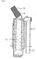
- FIG. 2 shows a cross section through the siphon 11 and connecting piece 14, the line 10 being latched in the connecting piece 14.
- the emerging from the line 10 Condensate 12 is collected in the siphon 11 and at the same time prevents the escape of exhaust gases through the condensate drainage 13th
- FIG. 3 illustrates the principle of latching and sealing of the plug connection in the region of the siphon connection 14.
- the interior of the siphon connection 14 has a sawtooth inner profile 15 in cross section.
- the sawtooth edges 17 rise from the opening side to the interior of the connecting piece 14 flat and then fall again steeply.
- the minimum inner diameter D min of the sawtooth on at least one sawtooth tip 18 is smaller than the maximum outer diameter d max of the line 10.
- the alternating profile of the line 10 should preferably be annular and have a rectangular profile with steeply rising and falling flanks.
- the elevations 19 and depressions 20 are repeated at periodic intervals.
- the line 10 When connecting the line 10 to the connecting piece 14, the line 10 is pressed by exerting a force in the connecting piece 14. Due to the force, the line 10 is compressed along its extension line. In addition, a radial expansion of the connecting piece 14 and / or a radial compression of the conduit 10 occur during insertion. This elasticity of at least one of the two components allows the insertion of the conduit 10 into the connecting piece 14. After the conduit 10 has been inserted into the connecting piece 14, the line 10 relaxes again. This has the consequence that the elevations 19 of the line 10 catch on the sawtooth edges 17 of the connecting piece 14 and thus seal against liquid and / or gas leaks.
- the distance l s of two sawtooth tips 18 preferably corresponds to an even multiple of the periodic distance l P from the line profile.
- This may be, for example, the distance between two elevations 19 or depressions 20 of the line profile.
- the choice of these distances causes a residual stress between the elevations 19 remains even after relaxing the line 10 in the mating area.
- For the latching are therefore responsible for the places where the elevations 19 at the steep catching falling flanks of sawgeffyinnenprofils 15.
- a secure sealing against liquid and / or gas leaks also takes place in the region of the steep sawtooth edges, but mainly at the points at which the elevations 19 are pressed against the flat flanks of the sawtooth inner profile 15 by the residual stress. An unintentional slipping out of the line 10, even when exposed to pressure, is thus avoided.
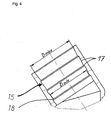
- FIG. 4 illustrates the connector in which the line 10 via the connection piece (9, 14) is inserted.
- the connector is constructed inversely to the previous embodiment.
- the underlying principle is identical to that explained with reference to FIG 3.
- the line 10 is plugged over and not into the connecting piece or condensate connection 9.
- the maximum outer diameter D max of the condensate connection 9 is at least one sawtooth tip 18 is greater than the minimum inner diameter d min of the line 10.
- the latching and sealing analogous to the connector of Figure 3, on the steep or flat sawtooth edges 17. Auch assume the seal or locking no longer the elevations 19, but the recesses 20 of the periodic conduction profile, which should preferably be formed rectangular.
- connection according to FIG. 4 it makes sense to select a connection according to FIG. 4 at the points at which liquid is led into the line 10 and, in the case of water outlets from the line 10, a plug connection according to FIG.
- a plug connection according to FIG.
- the principle of the connector is still the same.
- the connector can be accomplished manually with or without the aid of a device.
- a release of the Plug connection can finally by means of strong pulling on the line 10, by removing it from the connection piece (9, 14), take place.
- connection piece 14 or condensate connection 9 It is also possible to choose an aperiodic line profile, which, however, requires a correspondingly more specific embodiment of the connection piece 14 or condensate connection 9.
- the minimum inner diameter D min of the connecting piece 14 at the sawtooth tips 18 should decrease from the opening to the inside, preferably by the same values. This constriction leads to a better locking and sealing, since the deeper penetrated elevations 19 of the line 10 have a larger contact area with the steeply sloping sawtooth edges. The same effect is obtained when using a line 10 whose maximum outer diameter d max increases in the mating area from the interior to the opening, preferably by equal amounts. Also, the combination of a smaller inside diameter connecting piece 14 with an enlarging in the outer diameter line 10 is quite feasible.
- the above embodiment can be used in an analogous manner for the connector according to Figure 4 application.
- the maximum outer diameter D max at the sawtooth tips 18 then increases from the opening to the interior, preferably by the same values. It is also possible to use a line 10 whose minimum inner diameter d min is in the mating area from the interior to the opening, preferably by equal amounts. reduced. A combination of an enlarging in the outer diameter condensate connection 9 with a decreasing in the inner diameter line 10 is also practicable.
- An improvement in the tightness can be achieved by coating the line 10 and / or the connection piece 14 or condensate connection 9 with an elastomeric material in the region of the latching.
- the elastomeric material which is applied to the outer or inner surface of the conduit 10 and / or the connecting piece 14, for example by two-component injection molding seals better by its elastic nature and increases the static friction at the contact points between line 10 and connecting piece 14. Consequently, a release of the connector is counteracted even at higher pressures.
Landscapes
- Engineering & Computer Science (AREA)
- General Engineering & Computer Science (AREA)
- Mechanical Engineering (AREA)
- Chemical & Material Sciences (AREA)
- Thermal Sciences (AREA)
- Combustion & Propulsion (AREA)
- Physics & Mathematics (AREA)
- Quick-Acting Or Multi-Walled Pipe Joints (AREA)
- Coupling Device And Connection With Printed Circuit (AREA)
- Supports For Pipes And Cables (AREA)
- Multi-Conductor Connections (AREA)
- Pens And Brushes (AREA)
- Electric Cable Installation (AREA)
Abstract
Description
- Die Erfindung betrifft eine Steckverbindung mit Anschlussstutzen und Leitung.
- Beim Betrieb von Brennwertgeräten entsteht bei der Abkühlung von Wasserdampf Kondensat. Dieses wird unterhalb des Wärmetauschers aufgefangen und muss über eine Kondensatleitung abgeführt werden. Gleichzeitig muss ein Abgasaustritt aus der Kondensatleitung verhindert werden. Daher kommen Siphons zum Einsatz, in denen Kondensat den Abgasaustritt verhindert.
- Gemäß dem Stand der Technik wird ein Siphon mit dem Wärmetauscher über ein Rohr verbunden, das mittels einer Überwurfmutter oder Schelle verschraubt wird. Die bekannten Vorrichtungen weisen Nachteile hinsichtlich der Vielzahl der eingesetzten Bauteile auf. Zu den hohen Materialkosten treten Arbeitskosten für den erhöhten Montageaufwand hinzu.
- Aufgabe der vorliegenden Erfindung ist es, eine Steckverbindung zu schaffen, die kostengünstig ist und sich durch eine einfache Bauweise auszeichnet.
- Erfindungsgemäß wird obige Aufgabe durch die Merkmale des kennzeichnenden Teils des Anspruchs 1 gelöst.
- Weitere vorteilhafte Ausgestaltungen ergeben sich aus den Unteransprüchen.
- Gemäß den Merkmalen des Anspruches 2 werden eine sichere Abdichtung und eine stabile Verbindung durch ein Verhaken des Leitungsprofils am Profil des Anschlussstutzens gewährleistet. Hierbei kann optional eine leichte elastische Beanspruchung die dichte Verbindung begünstigen.
- Gemäß Anspruch 3 gewährleisten die steilen Flanken eines Rechteck- oder Wellenprofils eine stabile Verrastung und eine zuverlässige Abdichtung.
- Gemäß den Merkmalen des Anspruches 4 ermöglicht die Elastizität mindestens einer der an der Steckverbindung beteiligten Komponenten das Führen der Leitung in oder über den Anschlussstutzen.
- Gemäß den Merkmalen des Anspruches 5 bewirkt ein sich ändernder Durchmesser des Anschlussstutzens, aufgrund des stärkeren Ineinandergreifens von Sägezahn und Rechteckflanke, eine hohe Stabilität der Steckverbindung sowie ein zuverlässiges Abdichten.
- Gemäß den Merkmalen des Anspruches 6 kann die in Anspruch 5 genannte Stabilität der Steckverbindung und die Zuverlässigkeit der Abdichtung auch durch die Änderungen des Leitungsdurchmessers gewährleistet werden.
- Eine Ausführung nach Anspruch 7 verhindert ein Anstauen von Flüssigkeiten in den Vertiefungen des Leitungsprofils.
- Gemäß Anspruch 8 wird die Dichtwirkung durch ein elastomeres Element unterstützt.
- Anspruch 9 sieht den Einsatz der Erfindung in einem Heizgerät mit Siphon vor.
- In der Zeichnung zeigen:
- Fig. 1 eine schematische Anordnung einer Steckverbindung zwischen Abgas- und Kondensatsammler sowie dem Siphon eines Heizgerätes
- Fig. 2 einen Querschnitt durch einen Siphon mit Anschlussstutzen
- Fig. 3 eine erfindungsgemäße Lösung des Dichtheitsproblems an der Verbindungsstelle von Leitung und Siphonanschluss im Querschnitt
- Fig. 4 eine alternative Lösung des Dichtheitsproblems an einer Verbindungsstelle im Querschnitt
- Figur 1 zeigt ein Heizgerät mit einem Brenner 1, der über eine Gasarmatur 4 und ein Gebläse 3 mit einem Gas-Luft-Gemisch versorgt wird. Gasarmatur 4 und Gebläse 3 werden über eine Regelung 5 geregelt. Der Brenner 1 befindet sich zentrisch innerhalb des Wärmetauschers 2. Die sich im Wärmetauscher 2 bildenden Abgase und Kondensate werden über den Abgasaustritt 7 bzw. über den Kondensatanschluss 9 abgeführt. Mit dem Kondensatanschluss 9 ist eine Leitung 10 verbunden, über die das Kondensat in einen Siphon 11 abgeleitet wird. Zur Förderung der Kondensatableitung, muss der Anschlussstutzen 14 unterhalb des Kondensatanschlusses 9 platziert werden. Auf diese Weise kann allein über die Schwerkraft das Kondensat 12 zum Siphon 11 geleitet werden.
- Figur 2 zeigt einen Querschnitt durch den Siphon 11 und Anschlussstutzen 14, wobei die Leitung 10 im Anschlussstutzen 14 verrastet ist. Das aus der Leitung 10 tretende Kondensat 12 wird im Siphon 11 aufgefangen und verhindert gleichzeitig ein Entweichen von Abgasen über die Kondensatableitung 13.
- Figur 3 verdeutlicht das Prinzip der Verrastung und Abdichtung der Steckverbindung im Bereich des Siphonanschlusses 14. Das Innere des Siphonanschlusses 14 weist im Querschnitt ein Sägezahninnenprofil 15 auf. Die Sägezahnflanken 17 steigen dabei von der Öffnungsseite zum Inneren des Anschlussstutzens 14 flach an und fallen dann wieder steil ab. Dabei ist der minimale Innendurchmesser Dmin des Sägezahnprofils an mindestens einer Sägezahnspitze 18 kleiner als der maximale Außendurchmesser dmax der Leitung 10. Das alternierende Profil der Leitung 10 sollte dabei vorzugsweise ringförmig ausgebildet sein und ein Rechteckprofil mit steil auf- und absteigenden Flanken haben. Die Erhebungen 19 bzw. Vertiefungen 20 wiederholen sich dabei in periodischen Abständen.
- Bei der Verbindung der Leitung 10 mit dem Anschlussstutzen 14 wird die Leitung 10 durch Ausüben einer Kraft in den Anschlussstutzen 14 hineingedrückt. Durch die Kraft wird die Leitung 10 längs ihrer Erstreckungslinie gestaucht. Zusätzlich erfolgen beim Einführen eine radiale Dehnung des Anschlussstutzens 14 und/oder eine radiale Stauchung der Leitung 10. Diese Elastizität mindestens einer der beiden Komponenten ermöglicht das Einführen der Leitung 10 in den Anschlussstutzen 14. Nachdem die Leitung 10 in den Anschlussstutzen 14 gesteckt worden ist, entspannt sich die Leitung 10 wieder. Dies hat zur Folge, dass sich die Erhebungen 19 der Leitung 10 an den Sägezahnflanken 17 des Anschlussstutzens 14 verhaken und folglich gegen Flüssigkeits- und/oder Gasaustritte abdichten. Der Abstand ls zweier Sägezahnspitzen 18 entspricht dabei vorzugsweise einem geradzahligen Vielfachen des periodischen Abstands lP vom Leitungsprofil. Dies kann beispielsweise der Abstand zwischen zwei Erhebungen 19 bzw. Vertiefungen 20 des Leitungsprofils sein. Die Wahl dieser Abstände führt dazu, dass eine Restspannung zwischen den Erhebungen 19 auch nach dem Entspannen der Leitung 10 im Steckbereich bestehen bleibt. Für die Verrastung sind demzufolge die Stellen verantwortlich, an denen sich die Erhebungen 19 an den steil abfallenden Flanken des Sägezahninnenprofils 15 verhaken. Ein sicheres Abdichten gegen Flüssigkeits- und/oder Gasaustritte erfolgt ebenfalls im Bereich der steilen Sägezahnflanken, hauptsächlich aber an den Stellen, an denen die Erhebungen 19 an die flachen Flanken des Sägezahninnenprofils 15 durch die Restspannung gedrückt werden. Ein ungewolltes Herausrutschen der Leitung 10, selbst bei Einwirkung von Drücken, wird somit vermieden.
- Figur 4 veranschaulicht die Steckverbindung, bei der die Leitung 10 über den Anschlussstutzen (9, 14) gesteckt wird. Die Steckverbindung ist invers zum vorigen Ausführungsbeispiel aufgebaut. Das zugrunde liegende Prinzip ist jedoch identisch mit dem des anhand Figur 3 erläuterten. Der wesentliche Unterschied ist der, dass hier die Leitung 10 über und nicht in den Anschlussstutzen bzw. Kondensatanschluss 9 gesteckt wird. Anders als in Figur 3 ist es zweckmäßig, das Äußere des Kondensatanschlusses 9 mit einem Sägezahnprofil zu versehen, wobei die Sägezahnflanken 17 von der Öffnung zum Inneren flach ansteigen und dann wieder steil abfallen. Der maximale Außendurchmesser Dmax des Kondensatanschlusses 9 ist dabei an mindestens einer Sägezahnspitze 18 größer als der minimale Innendurchmesser dmin der Leitung 10. Die Verrastung und das Abdichten erfolgen, analog der Steckverbindung gemäß Figur 3, an den steilen bzw. flachen Sägezahnflanken 17. Auch übernehmen die Abdichtung bzw. Verrastung nicht mehr die Erhebungen 19, sondern die Vertiefungen 20 des periodischen Leitungsprofils, die vorzugsweise rechteckförmig ausgebildet sein sollten.
- Wie den obigen Ausführungen zu entnehmen ist, ist es sinnvoll, an den Stellen, an denen Flüssigkeit in die Leitung 10 geführt wird eine Verbindung gemäß Figur 4 und bei Wasseraustritten aus der Leitung 10 eine Steckverbindung entsprechend Figur 3 zu wählen. Natürlich kann dabei an die Stelle des Siphon- 14 oder Kondensatanschlusses 9 auch jeder denkbare Anschlussstutzen mit den oben erwähnten Merkmalen treten. Das Prinzip der Steckverbindung ist nach wie vor dasselbe. Die Steckverbindung kann mit oder ohne Zuhilfenahme einer Vorrichtung manuell bewerkstelligt werden. Ein Lösen der Steckverbindung kann schließlich mittels kräftiges Ziehen an der Leitung 10, durch dessen Entfernung vom Anschlussstutzen (9, 14), erfolgen.
- Im Bereich zwischen den beiden Steckverbindungen am Abgas- und Kondensatsammler 8 sowie am Siphon 11 kann von einem alternierenden Profil abgesehen werden, so dass Kondensflüssigkeit 12 möglichst gut in den Siphon 11 abfließen kann, ohne sich in den Vertiefungen 20 der Leitung 10 anzustauen. Auf diese Weise kann der Bildung von Ablagerungen in der Leitung 10 entgegengewirkt werden.
- Möglich ist auch die Wahl eines aperiodischen Leitungsprofils, was allerdings eine entsprechend speziellere Ausgestaltung des Anschlussstutzens 14 bzw. Kondensatanschlusses 9 erforderlich macht.
- Der minimale Innendurchmesser Dmin des Anschlussstutzens 14 an den Sägezahnspitzen 18 sollte sich von der Öffnung zum Inneren hin, vorzugsweise um gleiche Werte, verkleinern. Diese Verengung führt zu einer besseren Verrastung und Abdichtung, da die tiefer eingedrungenen Erhebungen 19 der Leitung 10 eine größere Kontaktfläche mit den steil abfallenden Sägezahnflanken haben. Denselben Effekt erhält man, wenn man eine Leitung 10 verwendet, dessen maximaler Außendurchmesser dmax sich im Steckbereich vom Inneren zur Öffnung hin, vorzugsweise um gleiche Beträge, vergrößert. Auch ist die Kombination eines sich im Innendurchmesser verkleinernden Anschlussstutzens 14 mit einer sich im Außendurchmesser vergrößernden Leitung 10 durchaus praktikabel.
- Die obige Ausführung kann in analoger Weise auch für die Steckverbindung gemäß Figur 4 Anwendung finden. Der maximale Außendurchmesser Dmax an den Sägezahnspitzen 18 vergrößert sich dann von der Öffnung zum Inneren hin vorzugsweise um gleiche Werte. Auch kann eine Leitung 10 herangezogen werden, dessen minimaler Innendurchmesser dmin sich im Steckbereich vom Inneren zur Öffnung hin, vorzugsweise um gleiche Beträge, verkleinert. Eine Kombination eines sich im Außendurchmesser vergrößernden Kondensatanschlusses 9 mit einer sich im Innendurchmesser verkleinernden Leitung 10 ist ebenfalls praktikabel.
- Eine Verbesserung der Dichtheit kann durch die Beschichtung der Leitung 10 und/oder des Anschlussstutzens 14 bzw. Kondensatanschlusses 9 mit einem elastomeren Material im Bereich der Verrastung bewerkstelligt werden. Das elastomere Material, das beispielsweise im Zwei-Komponenten-Spritzgussverfahren auf die äußere bzw. innere Oberfläche der Leitung 10 und/oder des Anschlussstutzens 14 aufgetragen wird, dichtet durch seine elastische Beschaffenheit besser ab und erhöht die Haftreibung an den Kontaktstellen zwischen Leitung 10 und Anschlussstutzen 14. Folglich wird einem Lösen der Steckverbindung auch bei größeren Drücken entgegenwirkt.
Claims (9)
- Steckverbindung mit Anschlussstutzen (9, 14) und Leitung (10), dadurch gekennzeichnet, dass der Anschlussstutzen (9, 14) ein in Aufnahmerichtung weisendes Sägezahninnen- (15) oder -außenprofil (16) hat, wobei die Sägezahnflanken (17) von der Öffnungsseite zum Inneren flach ansteigen, gefolgt von einem steilen Abfall, die Leitung (10) ein alternierendes Profil aufweist und bei einem Innenprofil (15) des Anschlussstutzens (14) der minimale Durchmesser (Dmin) an den Sägezahnspitzen (18) des Sägezahnprofils an mindestens einer Stelle kleiner als der maximale Außendurchmesser (dmax) des Leitungsprofils ist, während bei einem Außenprofil (16) des Anschlussstutzens (9) der maximale Durchmesser (Dmax) an den Sägezahnspitzen (18) des Sägezahnprofils an mindestens einer Stelle größer als der minimale Innendurchmesser (dmin) des Leitungsprofils ist.
- Steckverbindung mit Anschlussstutzen (9, 14) und Leitung (10) nach Anspruch 1, dadurch gekennzeichnet, dass der Abstand (ls) zwischen zwei Sägezahnspitzen (18) einem geradzahligen Vielfachen eines periodischen Leitungsprofils (lp) entspricht oder etwas kleiner ist.
- Steckverbindung mit Anschlussstutzen (9, 14) und Leitung (10) nach einem der Ansprüche 1 oder 2, dadurch gekennzeichnet, dass das alternierende periodische Leitungsprofil ein Rechteck- oder Wellenprofil ist.
- Steckverbindung mit Anschlussstutzen (9, 14) und Leitung (10) nach einem der Ansprüche 1 bis 3, dadurch gekennzeichnet, dass der Anschlussstutzen (9, 14) und/oder die Leitung (10) elastisch sind.
- Steckverbindung mit Anschlussstutzen (9, 14) und Leitung (10) nach einem der Ansprüche 1 bis 4, dadurch gekennzeichnet, dass der minimale Innen- (Dmin) bzw. maximale Außendurchmesser (Dmax) an den Sägezahnspitzen (18) sich von der Öffnung zum Inneren hin, vorzugsweise um gleiche Beträge, verkleinert bzw. vergrößert.
- Steckverbindung mit Anschlussstutzen (9, 14) und Leitung (10) nach einem der Ansprüche 1 bis 5, dadurch gekennzeichnet, dass der maximale Außen- (dmaX) bzw. minimale Innendurchmesser (dmin) der Leitung (10) sich insbesondere im Steckbereich vom Inneren zur Öffnung hin, vorzugsweise um gleiche Beträge, vergrößert bzw. verkleinert.
- Steckverbindung mit Anschlussstutzen (9, 14) und Leitung (10) nach einem der Ansprüche 1 bis 6, dadurch gekennzeichnet, dass die Leitung (10) zwischen den Steckbereichen kein alternierendes Profil aufweist.
- Steckverbindung mit Anschlussstutzen (9, 14) und Leitung (10) nach einem der Ansprüche 1 bis 7, dadurch gekennzeichnet, dass zwischen Anschlussstutzen (9, 14) und Leitung (10) sich eine elastomere Schicht, welche fest mit dem Anschlussstutzen (9, 14) und/oder der Leitung (10) verbunden ist, befindet.
- Heizgerät mit einem Siphon, welcher eine Steckverbindung gemäß einem der Ansprüche 1 bis 8 enthält.
Priority Applications (1)
| Application Number | Priority Date | Filing Date | Title |
|---|---|---|---|
| PL06003015T PL1696165T3 (pl) | 2005-02-24 | 2006-02-15 | Połączenie wtykowe z króćcem przyłączeniowym i przewodem |
Applications Claiming Priority (1)
| Application Number | Priority Date | Filing Date | Title |
|---|---|---|---|
| AT0030705A AT501505B1 (de) | 2005-02-24 | 2005-02-24 | Steckverbindung mit anschlussstutzen und leitung |
Publications (2)
| Publication Number | Publication Date |
|---|---|
| EP1696165A1 true EP1696165A1 (de) | 2006-08-30 |
| EP1696165B1 EP1696165B1 (de) | 2010-03-17 |
Family
ID=36587295
Family Applications (1)
| Application Number | Title | Priority Date | Filing Date |
|---|---|---|---|
| EP06003015A Expired - Lifetime EP1696165B1 (de) | 2005-02-24 | 2006-02-15 | Steckverbindung mit Anschlussstutzen und Leitung |
Country Status (5)
| Country | Link |
|---|---|
| EP (1) | EP1696165B1 (de) |
| AT (2) | AT501505B1 (de) |
| DE (1) | DE502006006421D1 (de) |
| DK (1) | DK1696165T3 (de) |
| PL (1) | PL1696165T3 (de) |
Cited By (4)
| Publication number | Priority date | Publication date | Assignee | Title |
|---|---|---|---|---|
| DE102015202395A1 (de) * | 2015-02-11 | 2016-08-11 | Vaillant Gmbh | Verbrennungstechnische oder elektrochemische Anlage mit Gebläse und Kondensatsiphon |
| WO2017089172A1 (de) * | 2015-11-26 | 2017-06-01 | Norma Germany Gmbh | Verbindungsanordnung für ein fluidsystem und verfahren zur herstellung einer verbindungsanordnung |
| EP3567295A1 (de) * | 2018-05-08 | 2019-11-13 | Vaillant GmbH | Siphon |
| CN113446448A (zh) * | 2020-03-26 | 2021-09-28 | 福士汽车配套部件责任有限公司 | 波纹管连接装置 |
Families Citing this family (1)
| Publication number | Priority date | Publication date | Assignee | Title |
|---|---|---|---|---|
| DE102007042605A1 (de) * | 2007-09-07 | 2009-03-12 | Witzenmann Gmbh | Anschlussvorrichtung für einen ringgewellten oder schraubengangförmig gewellten Metallschlauch oder Metallbalg, sowie Verfahren und Anordnung zum Herstellen eines solchen |
Citations (5)
| Publication number | Priority date | Publication date | Assignee | Title |
|---|---|---|---|---|
| GB2107814A (en) * | 1981-10-14 | 1983-05-05 | Roberto Fassina | An improved connection for tubes of elastomer material |
| FR2528533A1 (fr) * | 1982-06-09 | 1983-12-16 | Capri Codec Sa | Raccord traversant a ecrou tournant pour gaine exterieurement spiralee |
| FR2655126A1 (fr) * | 1989-11-30 | 1991-05-31 | Jaeger | Dispositif de raccordement etanche d'un tube annele sur une tubulure. |
| DE20104406U1 (de) * | 2001-03-14 | 2001-08-16 | Fränkische Rohrwerke Gebr. Kirchner GmbH + Co. KG, 97486 Königsberg | Kraftfahrzeugsichtscheibenspritzwasserzuführanordnung |
| EP1333214A1 (de) * | 2002-01-30 | 2003-08-06 | Fränkische Rohrwerke Gebr. Kirchner GmbH + Co KG | Anschlusseinrichtung zum wasserdichten Anschliessen eines Wellrohres |
Family Cites Families (3)
| Publication number | Priority date | Publication date | Assignee | Title |
|---|---|---|---|---|
| AT247080B (de) * | 1962-02-20 | 1966-05-25 | Inteco Establishment | Fitting für Kunststoffrohre |
| DE2738108A1 (de) * | 1977-08-24 | 1979-03-01 | Rainer Zschaubitz | Muffenrohrverbindung |
| SE503459C2 (sv) * | 1994-03-15 | 1996-06-17 | Atlas Copco Rocktech Ab | Anordning för permanent hopskarvning av rör |
-
2005
- 2005-02-24 AT AT0030705A patent/AT501505B1/de not_active IP Right Cessation
-
2006
- 2006-02-15 PL PL06003015T patent/PL1696165T3/pl unknown
- 2006-02-15 AT AT06003015T patent/ATE461393T1/de active
- 2006-02-15 EP EP06003015A patent/EP1696165B1/de not_active Expired - Lifetime
- 2006-02-15 DK DK06003015.2T patent/DK1696165T3/da active
- 2006-02-15 DE DE502006006421T patent/DE502006006421D1/de not_active Expired - Lifetime
Patent Citations (5)
| Publication number | Priority date | Publication date | Assignee | Title |
|---|---|---|---|---|
| GB2107814A (en) * | 1981-10-14 | 1983-05-05 | Roberto Fassina | An improved connection for tubes of elastomer material |
| FR2528533A1 (fr) * | 1982-06-09 | 1983-12-16 | Capri Codec Sa | Raccord traversant a ecrou tournant pour gaine exterieurement spiralee |
| FR2655126A1 (fr) * | 1989-11-30 | 1991-05-31 | Jaeger | Dispositif de raccordement etanche d'un tube annele sur une tubulure. |
| DE20104406U1 (de) * | 2001-03-14 | 2001-08-16 | Fränkische Rohrwerke Gebr. Kirchner GmbH + Co. KG, 97486 Königsberg | Kraftfahrzeugsichtscheibenspritzwasserzuführanordnung |
| EP1333214A1 (de) * | 2002-01-30 | 2003-08-06 | Fränkische Rohrwerke Gebr. Kirchner GmbH + Co KG | Anschlusseinrichtung zum wasserdichten Anschliessen eines Wellrohres |
Cited By (6)
| Publication number | Priority date | Publication date | Assignee | Title |
|---|---|---|---|---|
| DE102015202395A1 (de) * | 2015-02-11 | 2016-08-11 | Vaillant Gmbh | Verbrennungstechnische oder elektrochemische Anlage mit Gebläse und Kondensatsiphon |
| WO2017089172A1 (de) * | 2015-11-26 | 2017-06-01 | Norma Germany Gmbh | Verbindungsanordnung für ein fluidsystem und verfahren zur herstellung einer verbindungsanordnung |
| CN108291676A (zh) * | 2015-11-26 | 2018-07-17 | 德国诺玛公司 | 用于流体系统的连接组件及用于制造连接组件的方法 |
| EP3567295A1 (de) * | 2018-05-08 | 2019-11-13 | Vaillant GmbH | Siphon |
| CN113446448A (zh) * | 2020-03-26 | 2021-09-28 | 福士汽车配套部件责任有限公司 | 波纹管连接装置 |
| CN113446448B (zh) * | 2020-03-26 | 2023-11-28 | 福士汽车配套部件责任有限公司 | 波纹管连接装置 |
Also Published As
| Publication number | Publication date |
|---|---|
| AT501505A1 (de) | 2006-09-15 |
| PL1696165T3 (pl) | 2010-08-31 |
| DE502006006421D1 (de) | 2010-04-29 |
| DK1696165T3 (da) | 2010-06-07 |
| EP1696165B1 (de) | 2010-03-17 |
| AT501505B1 (de) | 2007-06-15 |
| ATE461393T1 (de) | 2010-04-15 |
Similar Documents
| Publication | Publication Date | Title |
|---|---|---|
| WO2014000911A1 (de) | Anschlussvorrichtung für rohrleitungen | |
| DE102010010522B4 (de) | Steckverbinder für Medienleitungen | |
| DE202004012795U1 (de) | Steckverbindung für Fluid-Leitungen | |
| EP2525126A1 (de) | Verbinder für eine beheizbare Fluidleitung und beheizbare Fluidleitung | |
| DE102015114776B4 (de) | Gasdichte Verbindung für Absaugeinrichtungen und Saugdüse für Staubsauger mit dieser Verbindung | |
| WO2019011661A1 (de) | Rohr, insbesondere kunststoffrohr für abwasserleitungen | |
| EP2025988A1 (de) | Fitting für ein Rohr, insbesondere Kunststoffrohr oder Kunststoff-Metall-Verbundrohr | |
| DE4205539A1 (de) | Zentralheizungsanlage und rohrkupplung hierfuer | |
| WO2015078539A1 (de) | Wasserfangvorrichtung | |
| EP1696165B1 (de) | Steckverbindung mit Anschlussstutzen und Leitung | |
| EP2975311B1 (de) | Schlauchverschraubung | |
| DE4443005A1 (de) | Kombination eines Luftschlauches und eines Anschlußstutzens sowie Anschlußstutzen hierfür | |
| EP1775507B1 (de) | Fitting für Rohrleitungen | |
| DE102017129559B4 (de) | Anschlusskopf für eine Filterkerze, Set mit einem Anschlusskopf sowie Filterkerze | |
| EP3884229A1 (de) | Kältegerät mit leitungsdurchführung | |
| DE3924795C2 (de) | Fluid-Anschlußeinrichtung | |
| DE102005038439A1 (de) | Steckverbindung für Fluid-Leitungen | |
| DE102012002943A1 (de) | Endstück, Anschlussstück und Anordnung von Endstück und Anschlussstück | |
| EP2366930A1 (de) | Vorrichtung zum Verbinden mit einer Rohr- oder Schlauchleitung, insbesondere Klemmringverschraubung | |
| EP3839316A1 (de) | Kupplungsteil für eine schlauchkupplung | |
| DE102005004147A1 (de) | Handhabungsvorrichtung zum Lösen und/oder Anschließen von insbesondere elastischen Rohren von/an Steckanschlusseinrichtungen | |
| EP0819797B1 (de) | Armatur mit Abläufen | |
| DE102007031741A1 (de) | Fluidverbindungsvorrichtung | |
| DE202015100034U1 (de) | Hahnverlängerung zur Verbindung einer Wasserleitung mit einer Armatur | |
| DE19702552A1 (de) | Schlauchfassung, insbesondere für Wellrohre |
Legal Events
| Date | Code | Title | Description |
|---|---|---|---|
| PUAI | Public reference made under article 153(3) epc to a published international application that has entered the european phase |
Free format text: ORIGINAL CODE: 0009012 |
|
| AK | Designated contracting states |
Kind code of ref document: A1 Designated state(s): AT BE BG CH CY CZ DE DK EE ES FI FR GB GR HU IE IS IT LI LT LU LV MC NL PL PT RO SE SI SK TR |
|
| AX | Request for extension of the european patent |
Extension state: AL BA HR MK YU |
|
| 17P | Request for examination filed |
Effective date: 20061208 |
|
| AKX | Designation fees paid |
Designated state(s): AT BE BG CH CY CZ DE DK EE ES FI FR GB GR HU IE IS IT LI LT LU LV MC NL PL PT RO SE SI SK TR |
|
| 17Q | First examination report despatched |
Effective date: 20080207 |
|
| GRAP | Despatch of communication of intention to grant a patent |
Free format text: ORIGINAL CODE: EPIDOSNIGR1 |
|
| GRAS | Grant fee paid |
Free format text: ORIGINAL CODE: EPIDOSNIGR3 |
|
| GRAA | (expected) grant |
Free format text: ORIGINAL CODE: 0009210 |
|
| AK | Designated contracting states |
Kind code of ref document: B1 Designated state(s): AT BE BG CH CY CZ DE DK EE ES FI FR GB GR HU IE IS IT LI LT LU LV MC NL PL PT RO SE SI SK TR |
|
| REG | Reference to a national code |
Ref country code: GB Ref legal event code: FG4D Free format text: NOT ENGLISH |
|
| REG | Reference to a national code |
Ref country code: CH Ref legal event code: EP |
|
| REG | Reference to a national code |
Ref country code: IE Ref legal event code: FG4D |
|
| REF | Corresponds to: |
Ref document number: 502006006421 Country of ref document: DE Date of ref document: 20100429 Kind code of ref document: P |
|
| REG | Reference to a national code |
Ref country code: DK Ref legal event code: T3 |
|
| REG | Reference to a national code |
Ref country code: NL Ref legal event code: T3 |
|
| REG | Reference to a national code |
Ref country code: RO Ref legal event code: EPE |
|
| PG25 | Lapsed in a contracting state [announced via postgrant information from national office to epo] |
Ref country code: LT Free format text: LAPSE BECAUSE OF FAILURE TO SUBMIT A TRANSLATION OF THE DESCRIPTION OR TO PAY THE FEE WITHIN THE PRESCRIBED TIME-LIMIT Effective date: 20100317 |
|
| REG | Reference to a national code |
Ref country code: SK Ref legal event code: T3 Ref document number: E 7196 Country of ref document: SK |
|
| LTIE | Lt: invalidation of european patent or patent extension |
Effective date: 20100317 |
|
| PG25 | Lapsed in a contracting state [announced via postgrant information from national office to epo] |
Ref country code: LV Free format text: LAPSE BECAUSE OF FAILURE TO SUBMIT A TRANSLATION OF THE DESCRIPTION OR TO PAY THE FEE WITHIN THE PRESCRIBED TIME-LIMIT Effective date: 20100317 Ref country code: FI Free format text: LAPSE BECAUSE OF FAILURE TO SUBMIT A TRANSLATION OF THE DESCRIPTION OR TO PAY THE FEE WITHIN THE PRESCRIBED TIME-LIMIT Effective date: 20100317 Ref country code: SI Free format text: LAPSE BECAUSE OF FAILURE TO SUBMIT A TRANSLATION OF THE DESCRIPTION OR TO PAY THE FEE WITHIN THE PRESCRIBED TIME-LIMIT Effective date: 20100317 |
|
| REG | Reference to a national code |
Ref country code: PL Ref legal event code: T3 |
|
| REG | Reference to a national code |
Ref country code: IE Ref legal event code: FD4D |
|
| REG | Reference to a national code |
Ref country code: HU Ref legal event code: AG4A Ref document number: E008134 Country of ref document: HU |
|
| PG25 | Lapsed in a contracting state [announced via postgrant information from national office to epo] |
Ref country code: GR Free format text: LAPSE BECAUSE OF FAILURE TO SUBMIT A TRANSLATION OF THE DESCRIPTION OR TO PAY THE FEE WITHIN THE PRESCRIBED TIME-LIMIT Effective date: 20100618 Ref country code: ES Free format text: LAPSE BECAUSE OF FAILURE TO SUBMIT A TRANSLATION OF THE DESCRIPTION OR TO PAY THE FEE WITHIN THE PRESCRIBED TIME-LIMIT Effective date: 20100628 Ref country code: CY Free format text: LAPSE BECAUSE OF FAILURE TO SUBMIT A TRANSLATION OF THE DESCRIPTION OR TO PAY THE FEE WITHIN THE PRESCRIBED TIME-LIMIT Effective date: 20100317 Ref country code: EE Free format text: LAPSE BECAUSE OF FAILURE TO SUBMIT A TRANSLATION OF THE DESCRIPTION OR TO PAY THE FEE WITHIN THE PRESCRIBED TIME-LIMIT Effective date: 20100317 Ref country code: SE Free format text: LAPSE BECAUSE OF FAILURE TO SUBMIT A TRANSLATION OF THE DESCRIPTION OR TO PAY THE FEE WITHIN THE PRESCRIBED TIME-LIMIT Effective date: 20100317 |
|
| PG25 | Lapsed in a contracting state [announced via postgrant information from national office to epo] |
Ref country code: IS Free format text: LAPSE BECAUSE OF FAILURE TO SUBMIT A TRANSLATION OF THE DESCRIPTION OR TO PAY THE FEE WITHIN THE PRESCRIBED TIME-LIMIT Effective date: 20100717 Ref country code: BG Free format text: LAPSE BECAUSE OF FAILURE TO SUBMIT A TRANSLATION OF THE DESCRIPTION OR TO PAY THE FEE WITHIN THE PRESCRIBED TIME-LIMIT Effective date: 20100617 |
|
| PLBE | No opposition filed within time limit |
Free format text: ORIGINAL CODE: 0009261 |
|
| STAA | Information on the status of an ep patent application or granted ep patent |
Free format text: STATUS: NO OPPOSITION FILED WITHIN TIME LIMIT |
|
| PG25 | Lapsed in a contracting state [announced via postgrant information from national office to epo] |
Ref country code: IE Free format text: LAPSE BECAUSE OF FAILURE TO SUBMIT A TRANSLATION OF THE DESCRIPTION OR TO PAY THE FEE WITHIN THE PRESCRIBED TIME-LIMIT Effective date: 20100317 Ref country code: PT Free format text: LAPSE BECAUSE OF FAILURE TO SUBMIT A TRANSLATION OF THE DESCRIPTION OR TO PAY THE FEE WITHIN THE PRESCRIBED TIME-LIMIT Effective date: 20100719 |
|
| 26N | No opposition filed |
Effective date: 20101220 |
|
| PG25 | Lapsed in a contracting state [announced via postgrant information from national office to epo] |
Ref country code: MC Free format text: LAPSE BECAUSE OF NON-PAYMENT OF DUE FEES Effective date: 20110228 |
|
| REG | Reference to a national code |
Ref country code: DK Ref legal event code: EBP |
|
| PG25 | Lapsed in a contracting state [announced via postgrant information from national office to epo] |
Ref country code: RO Free format text: LAPSE BECAUSE OF NON-PAYMENT OF DUE FEES Effective date: 20100317 |
|
| PG25 | Lapsed in a contracting state [announced via postgrant information from national office to epo] |
Ref country code: LU Free format text: LAPSE BECAUSE OF NON-PAYMENT OF DUE FEES Effective date: 20110215 |
|
| REG | Reference to a national code |
Ref country code: FR Ref legal event code: PLFP Year of fee payment: 10 |
|
| REG | Reference to a national code |
Ref country code: DE Ref legal event code: R081 Ref document number: 502006006421 Country of ref document: DE Owner name: GEALAN FORMTEILE GMBH, DE Free format text: FORMER OWNER: GEALAN FORMTEILE GMBH, VAILLANT GMBH, , DE Effective date: 20150212 Ref country code: DE Ref legal event code: R081 Ref document number: 502006006421 Country of ref document: DE Owner name: GEALAN FORMTEILE GMBH, DE Free format text: FORMER OWNERS: GEALAN FORMTEILE GMBH, 95145 OBERKOTZAU, DE; VAILLANT GMBH, 42859 REMSCHEID, DE Effective date: 20150212 |
|
| REG | Reference to a national code |
Ref country code: CH Ref legal event code: PUEA Owner name: GEALAN FORMTEILE GMBH, DE Free format text: FORMER OWNER: VAILLANT GMBH, DE |
|
| REG | Reference to a national code |
Ref country code: NL Ref legal event code: SD Effective date: 20150811 |
|
| REG | Reference to a national code |
Ref country code: GB Ref legal event code: 732E Free format text: REGISTERED BETWEEN 20150730 AND 20150805 |
|
| REG | Reference to a national code |
Ref country code: AT Ref legal event code: PC Ref document number: 461393 Country of ref document: AT Kind code of ref document: T Owner name: GEALAN FORMTEILE GMBH, DE Effective date: 20150901 |
|
| PG25 | Lapsed in a contracting state [announced via postgrant information from national office to epo] |
Ref country code: RO Free format text: LAPSE BECAUSE OF NON-PAYMENT OF DUE FEES Effective date: 20150215 |
|
| PGFP | Annual fee paid to national office [announced via postgrant information from national office to epo] |
Ref country code: PL Payment date: 20151201 Year of fee payment: 11 |
|
| REG | Reference to a national code |
Ref country code: FR Ref legal event code: PLFP Year of fee payment: 11 |
|
| PGFP | Annual fee paid to national office [announced via postgrant information from national office to epo] |
Ref country code: IT Payment date: 20160224 Year of fee payment: 11 |
|
| PGFP | Annual fee paid to national office [announced via postgrant information from national office to epo] |
Ref country code: BE Payment date: 20160225 Year of fee payment: 11 Ref country code: AT Payment date: 20160301 Year of fee payment: 11 |
|
| REG | Reference to a national code |
Ref country code: HU Ref legal event code: FH1C Ref country code: HU Ref legal event code: GB9C Owner name: GEALAN FORMTEILE GMBH, DE Free format text: FORMER OWNER(S): GEALAN FORMTEILE GMBH, DE; VAILLANT GMBH, DE |
|
| REG | Reference to a national code |
Ref country code: FR Ref legal event code: TP Owner name: GEALAN FORMTEILE GMBH, DE Effective date: 20160621 |
|
| REG | Reference to a national code |
Ref country code: SK Ref legal event code: PC4A Ref document number: E 7196 Country of ref document: SK Owner name: GEALAN FORMTEILE GMBH, OBERKOTZAU, DE Free format text: FORMER OWNER: GEALAN FORMTEILE GMBH, OBERKOTZAU, DE; VAILLANT GMBH, REMSCHEID, DE Effective date: 20160815 |
|
| REG | Reference to a national code |
Ref country code: FR Ref legal event code: PLFP Year of fee payment: 12 |
|
| PGFP | Annual fee paid to national office [announced via postgrant information from national office to epo] |
Ref country code: RO Payment date: 20161122 Year of fee payment: 11 |
|
| PG25 | Lapsed in a contracting state [announced via postgrant information from national office to epo] |
Ref country code: BE Free format text: LAPSE BECAUSE OF NON-PAYMENT OF DUE FEES Effective date: 20170228 |
|
| REG | Reference to a national code |
Ref country code: AT Ref legal event code: MM01 Ref document number: 461393 Country of ref document: AT Kind code of ref document: T Effective date: 20170215 |
|
| PG25 | Lapsed in a contracting state [announced via postgrant information from national office to epo] |
Ref country code: RO Free format text: LAPSE BECAUSE OF NON-PAYMENT OF DUE FEES Effective date: 20170215 Ref country code: AT Free format text: LAPSE BECAUSE OF NON-PAYMENT OF DUE FEES Effective date: 20170215 |
|
| REG | Reference to a national code |
Ref country code: BE Ref legal event code: MM Effective date: 20170228 Ref country code: BE Ref legal event code: PD Owner name: GEALAN FORMTEILE GMBH; DE Free format text: DETAILS ASSIGNMENT: CHANGE OF OWNER(S), AFFECTATION / CESSION; FORMER OWNER NAME: VAILLANT GMBH Effective date: 20150618 |
|
| REG | Reference to a national code |
Ref country code: FR Ref legal event code: PLFP Year of fee payment: 13 |
|
| PG25 | Lapsed in a contracting state [announced via postgrant information from national office to epo] |
Ref country code: IT Free format text: LAPSE BECAUSE OF NON-PAYMENT OF DUE FEES Effective date: 20170215 |
|
| PG25 | Lapsed in a contracting state [announced via postgrant information from national office to epo] |
Ref country code: PL Free format text: LAPSE BECAUSE OF NON-PAYMENT OF DUE FEES Effective date: 20170215 |
|
| PGFP | Annual fee paid to national office [announced via postgrant information from national office to epo] |
Ref country code: NL Payment date: 20190225 Year of fee payment: 14 |
|
| PGFP | Annual fee paid to national office [announced via postgrant information from national office to epo] |
Ref country code: SE Payment date: 20190219 Year of fee payment: 19 |
|
| PGFP | Annual fee paid to national office [announced via postgrant information from national office to epo] |
Ref country code: CZ Payment date: 20200212 Year of fee payment: 15 |
|
| REG | Reference to a national code |
Ref country code: CH Ref legal event code: PL |
|
| REG | Reference to a national code |
Ref country code: NL Ref legal event code: MM Effective date: 20200301 |
|
| PG25 | Lapsed in a contracting state [announced via postgrant information from national office to epo] |
Ref country code: CH Free format text: LAPSE BECAUSE OF NON-PAYMENT OF DUE FEES Effective date: 20200229 Ref country code: HU Free format text: LAPSE BECAUSE OF NON-PAYMENT OF DUE FEES Effective date: 20200216 Ref country code: LI Free format text: LAPSE BECAUSE OF NON-PAYMENT OF DUE FEES Effective date: 20200229 |
|
| PG25 | Lapsed in a contracting state [announced via postgrant information from national office to epo] |
Ref country code: NL Free format text: LAPSE BECAUSE OF NON-PAYMENT OF DUE FEES Effective date: 20200301 |
|
| PGFP | Annual fee paid to national office [announced via postgrant information from national office to epo] |
Ref country code: FR Payment date: 20210223 Year of fee payment: 16 |
|
| PGFP | Annual fee paid to national office [announced via postgrant information from national office to epo] |
Ref country code: TR Payment date: 20210211 Year of fee payment: 16 |
|
| PG25 | Lapsed in a contracting state [announced via postgrant information from national office to epo] |
Ref country code: CZ Free format text: LAPSE BECAUSE OF NON-PAYMENT OF DUE FEES Effective date: 20210215 |
|
| PG25 | Lapsed in a contracting state [announced via postgrant information from national office to epo] |
Ref country code: FR Free format text: LAPSE BECAUSE OF NON-PAYMENT OF DUE FEES Effective date: 20220228 |
|
| PGFP | Annual fee paid to national office [announced via postgrant information from national office to epo] |
Ref country code: DE Payment date: 20240119 Year of fee payment: 19 Ref country code: GB Payment date: 20240220 Year of fee payment: 19 Ref country code: SK Payment date: 20240129 Year of fee payment: 19 |
|
| PG25 | Lapsed in a contracting state [announced via postgrant information from national office to epo] |
Ref country code: TR Free format text: LAPSE BECAUSE OF NON-PAYMENT OF DUE FEES Effective date: 20220215 |
|
| REG | Reference to a national code |
Ref country code: DE Ref legal event code: R119 Ref document number: 502006006421 Country of ref document: DE |
|
| REG | Reference to a national code |
Ref country code: SK Ref legal event code: MM4A Ref document number: E 7196 Country of ref document: SK Effective date: 20250215 |
|
| PG25 | Lapsed in a contracting state [announced via postgrant information from national office to epo] |
Ref country code: SK Free format text: LAPSE BECAUSE OF NON-PAYMENT OF DUE FEES Effective date: 20250215 |
|
| GBPC | Gb: european patent ceased through non-payment of renewal fee |
Effective date: 20250215 |
|
| PG25 | Lapsed in a contracting state [announced via postgrant information from national office to epo] |
Ref country code: DE Free format text: LAPSE BECAUSE OF NON-PAYMENT OF DUE FEES Effective date: 20250902 |
|
| PG25 | Lapsed in a contracting state [announced via postgrant information from national office to epo] |
Ref country code: GB Free format text: LAPSE BECAUSE OF NON-PAYMENT OF DUE FEES Effective date: 20250215 |