EP1693177A2 - Heizzylinder zum Aufschieben auf eine Spritzdüse für eine Spritzgiessanlage - Google Patents
Heizzylinder zum Aufschieben auf eine Spritzdüse für eine Spritzgiessanlage Download PDFInfo
- Publication number
- EP1693177A2 EP1693177A2 EP06002031A EP06002031A EP1693177A2 EP 1693177 A2 EP1693177 A2 EP 1693177A2 EP 06002031 A EP06002031 A EP 06002031A EP 06002031 A EP06002031 A EP 06002031A EP 1693177 A2 EP1693177 A2 EP 1693177A2
- Authority
- EP
- European Patent Office
- Prior art keywords
- heating
- nozzle
- cylinder
- conductor
- cartridge
- Prior art date
- Legal status (The legal status is an assumption and is not a legal conclusion. Google has not performed a legal analysis and makes no representation as to the accuracy of the status listed.)
- Granted
Links
Images

Classifications
-
- H—ELECTRICITY
- H05—ELECTRIC TECHNIQUES NOT OTHERWISE PROVIDED FOR
- H05B—ELECTRIC HEATING; ELECTRIC LIGHT SOURCES NOT OTHERWISE PROVIDED FOR; CIRCUIT ARRANGEMENTS FOR ELECTRIC LIGHT SOURCES, IN GENERAL
- H05B3/00—Ohmic-resistance heating
- H05B3/40—Heating elements having the shape of rods or tubes
- H05B3/42—Heating elements having the shape of rods or tubes non-flexible
-
- B—PERFORMING OPERATIONS; TRANSPORTING
- B29—WORKING OF PLASTICS; WORKING OF SUBSTANCES IN A PLASTIC STATE IN GENERAL
- B29C—SHAPING OR JOINING OF PLASTICS; SHAPING OF MATERIAL IN A PLASTIC STATE, NOT OTHERWISE PROVIDED FOR; AFTER-TREATMENT OF THE SHAPED PRODUCTS, e.g. REPAIRING
- B29C45/00—Injection moulding, i.e. forcing the required volume of moulding material through a nozzle into a closed mould; Apparatus therefor
- B29C45/17—Component parts, details or accessories; Auxiliary operations
- B29C45/26—Moulds
- B29C45/27—Sprue channels ; Runner channels or runner nozzles
- B29C45/2737—Heating or cooling means therefor
-
- B—PERFORMING OPERATIONS; TRANSPORTING
- B29—WORKING OF PLASTICS; WORKING OF SUBSTANCES IN A PLASTIC STATE IN GENERAL
- B29C—SHAPING OR JOINING OF PLASTICS; SHAPING OF MATERIAL IN A PLASTIC STATE, NOT OTHERWISE PROVIDED FOR; AFTER-TREATMENT OF THE SHAPED PRODUCTS, e.g. REPAIRING
- B29C45/00—Injection moulding, i.e. forcing the required volume of moulding material through a nozzle into a closed mould; Apparatus therefor
- B29C45/17—Component parts, details or accessories; Auxiliary operations
- B29C45/26—Moulds
- B29C45/27—Sprue channels ; Runner channels or runner nozzles
- B29C45/2737—Heating or cooling means therefor
- B29C2045/2743—Electrical heating element constructions
-
- B—PERFORMING OPERATIONS; TRANSPORTING
- B29—WORKING OF PLASTICS; WORKING OF SUBSTANCES IN A PLASTIC STATE IN GENERAL
- B29C—SHAPING OR JOINING OF PLASTICS; SHAPING OF MATERIAL IN A PLASTIC STATE, NOT OTHERWISE PROVIDED FOR; AFTER-TREATMENT OF THE SHAPED PRODUCTS, e.g. REPAIRING
- B29C45/00—Injection moulding, i.e. forcing the required volume of moulding material through a nozzle into a closed mould; Apparatus therefor
- B29C45/17—Component parts, details or accessories; Auxiliary operations
- B29C45/26—Moulds
- B29C45/27—Sprue channels ; Runner channels or runner nozzles
- B29C45/2737—Heating or cooling means therefor
- B29C2045/2754—Plurality of independent heating or cooling means, e.g. independently controlling the heating of several zones of the nozzle
Definitions
- the present invention relates to a heating cylinder for sliding onto a spray nozzle for an injection molding plant according to the preamble of claim 1.
- Figure 1 shows a schematic representation of an injection molding. From a connected via a sprue bushing 3 injection molding hot melt is passed through the flow channels 4 of a heated hot runner manifold block 2 to the nozzles 10. The spray nozzles 10 are located in the receiving bores 8 in the injection side part 5 of the tool 5.6. The spray nozzles are connected via the so-called gate 13 to the cavities 7, in which the molded parts are formed and which are usually located in the discharge side part 6 of the tool.
- the processing temperature is the melt 250 ° C
- the tool has a temperature of 50 ° C.
- This temperature difference has a considerable heat flow from the nozzle, in particular at the contact points between the nozzle and the tool. This heat loss must be compensated by heating the nozzles constantly. This heating takes place by means of slidable on the nozzles heating cylinder, to which the present invention relates.
- the most critical point with respect to the risk of supercooling of the melt is at the gate 13, since the heat capacity of the surrounding nozzle material is small due to the smaller diameter of the nozzle and there is intimate contact of the nozzle with the tool.
- the heating of the nozzle in the gate area 12 must be stronger than in the shaft area 11.
- the required for this purpose in the gate area 12 heat is also highly dependent on the operating conditions, the material of melt and tool and the shape of the gate 13.
- the heat input can be easily controlled, since the bandwidth of the processing temperature of some melts is very narrow. Further, for example, in the cold state of the tool the gate area 12 an increased amount of heat must be supplied.
- the heating conductors of both heating cylinders can be controlled or regulated independently of one another.
- the heating cylinder consist essentially of a hollow support cylinder, which is provided with a spiral groove for receiving a heating element, in which a heating element is embedded.
- the slope of the spiral groove on the support cylinder of the heating cylinder for the gate area 12 is usually smaller than the pitch of the spiral groove on the support cylinder for the Shank region 11.
- On the outside of the heating cylinder is a metallic protective jacket 23. In Figure 2, except the image of the nozzle and the receiving bore 8 indicated in the tool.
- the present invention has for its object to further develop the known heating arrangement of the nozzle in an advantageous manner.
- the inventive solution only a heating cylinder instead of two separate heating cylinders as in the known solution is required.
- the space required in the cable duct of the system is reduced, since only one ISO hose for two heating connections is required.
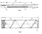
- the embodiment of a heating cartridge according to the invention shown in Figure 4 includes two heating conductors 32 and 33 which are wound into helical heating coils.
- the heating coils are housed in a metal sleeve 31, in which they are in an electrical insulation, not shown are embedded.
- the heating coil 32 is located in the front (tool-side) part of the metal sleeve 31 and the heating coil 33, which is spatially and galvanically separated from the heating coil 32, in the remaining part of the metal sleeve 31.
- the electrical connections 34 and 35 of both heating coils are on the heating coil 32 opposite end led out of the metal sleeve 31.
- the heating cartridge 30 is very long in relation to its diameter, which is not reflected in Figure 4, which shows only symbolically the structure of the heating element. It is like a long plastically deformable rod or a wire.
- This heating cartridge is wound on the hollow support cylinder 21 shown in FIG.
- the outside of the support cylinder 21 is provided with a helical groove 22 which has a significantly smaller pitch in its portion-side region Ba than in its shaft region Bs.
- the lengths of the heating coils 32, 33 are matched to the support cylinder, that the tightly-wound turns of the spiral groove 22 in the gate area Ba are substantially occupied by the heating coil 32, and the large-pitched turns of the spiral groove 22 in the shaft area Bs are substantially occupied by the heating coil 33.
- the connections 34 and 35 of both heating coils are led out of the heating cylinder at A (FIG. 5).
- a protective jacket 23 not shown in FIG. 5, but designated in FIG.
- FIG. 3 shows a spray nozzle onto which the hollow heating cylinder according to the invention is pushed. It can be seen that the entire spray nozzle 10 has no radially projecting parts along its entire length as the known spray nozzle according to Figure 2. It can be seen further that the indicated Receiving bore 8 of the tool without the required in the prior art groove 9 (see Figure 2) manages.
- the electrical connections 34, 35 of both heating coils are located at the end of the nozzle facing away from the tool outside of the receiving bore 8.
- the thin leads for the temperature sensor in the gate area and the shaft area are each in a small longitudinal groove 24 and 25 in the protective jacket 23, which it in the radial direction to no extension comes.
- the heating can, as already in the prior art, be controlled or regulated separately in the gate area and in the shaft area of the nozzle.
- the greater density of turns of the heating cartridge 30 on the support cylinder 21 in the gate area Ba is therefore not necessary in principle.
- the current carrying capacity of the heating coil 32 should be higher than that of the heating coil 33, with the result that the heating coils in both areas would have to be electrically dimensioned differently.
Landscapes
- Engineering & Computer Science (AREA)
- Manufacturing & Machinery (AREA)
- Mechanical Engineering (AREA)
- Injection Moulding Of Plastics Or The Like (AREA)
- Nozzles (AREA)
- Catching Or Destruction (AREA)
Abstract
Description
- Die vorliegende Erfindung bezieht sich auf einen Heizzylinder zum Aufschieben auf eine Spritzdüse für eine Spritzgießanlage gemäß dem Oberbegriff des Anspruches 1.
- Zum Verständnis des der Erfindung zugrunde liegenden Problems wird auf die Figuren 1 und 2 Bezug genommen. Figur 1 zeigt in schematischer Darstellung eine Spritzgießanlage. Von einer über eine Angußbuchse 3 angeschlossenen Spritzgießmaschine wird heiße Schmelze durch die Fließkanäle 4 eines beheizten Heißkanal-Verteilerblocks 2 zu den Düsen 10 geleitet. Die Spritzdüsen 10 befinden sich in den Aufnahmebohrungen 8 im Spritzseitenteil 5 des Werkzeugs 5,6. Die Spritzdüsen sind über den sogenannten Anschnitt 13 an die Kavitäten 7 angeschlossen, in denen die Spritzteile geformt werden und die sich gewöhnlich im Auswurfseitenteil 6 des Werkzeugs befinden.
- Zwischen der erforderlichen Temperatur der Schmelze und der des Werkzeugs besteht im Betrieb ein beträchtlicher Unterschied. Beispielsweise beträgt die Verarbeitungstemperatur der Schmelze 250°C, während das Werkzeug eine Temperatur von 50°C hat. Dieser Temperaturunterschied hat insbesondere an den Berührungsstellen zwischen Düse und Werkzeug einen erheblichen Wärmeabfluß von der Düse zur Folge. Dieser Wärmeverlust muß durch Beheizung der Düsen ständig ausgeglichen werden. Diese Beheizung erfolgt mittels auf die Düsen aufschiebbarer Heizzylinder, auf die sich die vorliegende Erfindung bezieht. Die kritischste Stelle hinsichtlich der Gefahr einer Unterkühlung der Schmelze liegt am Anschnitt 13, da hier die Wärmekapazität des umgebenden Düsenmaterials infolge des kleiner werden Durchmessers der Düse gering ist und ein inniger Kontakt der Düse mit dem Werkzeug besteht.
- Diese Verhältnisse erfordern, daß die Beheizung der Düse im Anschnittbereich 12 stärker sein muß als im Schaftbereich 11. Die hierfür im Anschnittbereich 12 erforderliche Wärmezufuhr ist auch stark abhängig von den Betriebsbedingungen, dem Material von Schmelze und Werkzeug und der Gestalt des Anschnitts 13. Außerdem muß die Wärmezufuhr gut regelbar sein, da die Bandbreite der Verarbeitungstemperatur mancher Schmelzen sehr schmall ist. Ferner muß beispielsweise im kalten zustand des Werkzeugs dem Anschnittsbereich 12 eine erhöhte Wärmemenge zugeführt werden.
- Es ist bereits bekannt, die Düsen mit zwei getrennten Heizzylindern 20a, 20b (Figur 2) auszurüsten, und zwar einen für den Anschnittbereich 12 und einen für den Schaftbereich 11. Die Heizleiter beider Heizzylinder sind unabhängig voneinander steuerbar beziehungsweise regelbar. Die Heizzylinder bestehen im wesentlichen aus einen hohlen Tragzylinder, der mit einer Spiralnut für die Aufnahme einer Heizpatrone versehen ist, in welche ein Heizleiter eingebettet ist. Die Steigung der Spiralnut auf den Tragzylinder des Heizzylinders für den Anschnittbereich 12 ist in der Regel kleiner als die Steigung der Spiralnut auf dem Tragzylinder für den Schaftbereich 11. An der Außenseite der Heizzylinder befindet sich eine metallische Schutzmantel 23. In Figur 2 ist außer der Abbildung der Düse auch die Aufnahmebohrung 8 im Werkzeug angedeutet.
- Der Nachteil dieser bekannten Lösung besteht zum einen darin, daß zwei getrennte Heizzylinder 20a, 20b erforderlich sind. Ein weiterer wesentlicher Nachteil besteht darin, daß der elektrische Anschluß 34 des Heizzylinders 20a für den Anschnittbereich ziemlich weit vorne in Richtung zum Anschnitt liegt, so daß zu seiner Unterbringung in der Aufnahmebohrung 8 des Werkzeug-Spritzseitenteils 5 eine entsprechende Längsnut 9 (Figur 2) vorgesehen werden muß. Diese Notwendigkeit kann, abgesehen von dem zusätzlichen Aufwand, bei manchen Werkzeugen auch zu Platzproblemen führen. Ferner besteht eine erhebliche Beschädigungsgefahr für den elektrischen Anschluß 34 beim Einführen der Düsen in die Aufnahmebohrungen 8 des Werkzeugs. In Figur 2 bezeichnet 35a den Anschluß an den Temperaturfühler für den Heizzylinder 20b. Der entsprechende Temperaturfühler für den Heizzylinder 20a ist nicht dargestellt.
- Der vorliegenden Erfindung liegt die Aufgabe zugrunde, die bekannte Beheizungsanordnung der Düse in vorteilhafter Weise weiter zu entwickeln.
- Zur Lösung dieser Aufgabe wird ein Heizzylinder gemäß dem Oberbegriff des Anspruches 1 vorgeschlagen, welcher die im kennzeichnenden Teil des Anspruches 1 genannten Merkmale hat.
- Weitere Ausgestaltungen der Erfindung sind in den Unteransprüchen genannt.
- Durch die erfindungsgemäße Lösung ist nur noch ein Heizzylinder anstelle von zwei getrennten Heizzylindern wie bei der bekannten Lösung erforderlich. Damit entfällt der elektrische Anschluß 34, der beim Stand der Technik im Anschnittbereich aus dem zylindrischen Körper des Heizzylinders radial nach außen hervortritt. Folglich kann auf die Aufnahmenut 9 für diesen Anschluß in der Düsen-Aufnahmebohrung 8 des Werkzeugs verzichtet werden. Ferner wird der Platzbedarf im Kabelkanal der Anlage reduziert, da nur ein ISO-Schlauch für zwei Heizungsanschlüsse erforderlich ist. Diese Vereinfachungen sind mit einer erheblichen Kostenersparnis verbunden.
- Anhand der Figuren soll die Erfindung näher erläutert werden. Es zeigen:
- Figur 1
- skizzenhaft eine Spritzgießanlage nach dem Stande der Technik,
- Figur 2
- eine Spritzdüse mit zwei getrennten Heizzylindern nach dem Stande der Technik,
- Figur 3
- eine Spritzdüse mit einem Ausführungsbeispiel eines einheitlichen Heizzylinders gemäß der Erfindung,
- Figur 4
- ein Ausführungsbeispiel einer Heizpatrone für einen Heizzylinder gemäß der Erfindung,
- Figur 5
- ein Ausführungsbeispiel des Tragzylinders für einen Heizzylinder gemäß der Erfindung.
- Das in Figur 4 gezeigte Ausführungsbeispiel einer Heizpatrone gemäß der Erfindung enthält zwei Heizleiter 32 und 33, die zu spiralförmigen Heizwendeln gewickelt sind. Die Heizwendeln sind in einer Metallhülse 31 untergebracht, in der sie in einer nicht dargestellten elektrischen Isoliermasse eingebettet sind. Die Heizwendel 32 befindet sich im vorderen (werkzeugseitigen) Teil der Metallhülse 31 und die Heizwendel 33, die räumlich und galvanisch von der Heizwendel 32 getrennt ist, im übrigen Teil der Metallhülse 31. Die elektrischen Anschlüsse 34 und 35 beider Heizwendeln sind an dem der Heizwendel 32 abgewandten Ende aus der Metallhülse 31 herausgeführt.
- Die Heizpatrone 30 ist im Verhältnis zu ihrem Durchmesser sehr lang, was in Figur 4, die nur symbolisch den Aufbau der Heizpatrone zeigt, nicht zum Ausdruck kommt. Sie gleicht einer langen plastisch verformbaren Stange oder einem Draht. Diese Heizpatrone wird auf den in Figur 5 gezeigten hohlen Tragzylinder 21 gewickelt. Zur Führung der aufzuwickelnden Heizpatrone ist die Außenseite des Tragzylinders 21 mit einer spiralförmigen Nut 22 versehen, die in ihrem anschnittseitigen Bereich Ba eine bedeutend kleinere Steigung aufweist als in ihrem Schaftbereich Bs. Die Längen der Heizwendeln 32, 33 sind so auf den Tragzylinder abgestimmt, daß die dicht beeinanderliegenden Windungen der Spiralnut 22 im Anschnittsbereich Ba im wesentlichen von der Heizwendel 32 eingenommen werden, und die mit großer Steigerung versehenen Windungen der Spiralnut 22 im Schaftbereich Bs im wesentlichen von der Heizwendel 33 eingenommen werden. Die Anschlüsse 34 und 35 beider Heizwendeln werden bei A (Figur 5) aus dem Heizzylinder herausgeführt. Radial außerhalb des mit der Heizpatrone 30 versehenen Tragzylinders 21 ist zum Schutz noch ein in Figur 5 nicht dargestellter, aber in Figur 3 bezeichneter Schutzmantel 23 vorhanden.
- Figur 3 zeigt eine Spritzdüse, auf die der hohle Heizzylinder gemäß der Erfindung aufgeschoben ist. Man erkennt, daß die komplette Spritzdüse 10 auf ihrer gesamten Länge keine radial vorspringenden Teile aufweist wie die bekannte Spritzdüse gemäß Figur 2. Man erkennt ferner, daß die angedeutete Aufnahmebohrung 8 des Werkzeugs ohne die beim Stand der Technik erforderliche Nut 9 (siehe Figur 2) auskommt. Die elektrischen Anschlüsse 34, 35 beider Heizwendeln befinden sich an dem dem Werkzeug abgewandten Ende der Düse außerhalb der Aufnahmebohrung 8. Die dünnen Anschlußleiter für die Temperaturfühler im Anschnittsbereich und im Schaftbereich liegen in je einer kleinen Längsnut 24 bzw. 25 im Schutzmantel 23, wodurch es in radialer Richtung zu keiner Erweiterung kommt.
- Die Beheizung kann, wie auch bereits im Stande der Technik, im Anschnittbereich und im Schaftbereich der Düse getrennt gesteuert oder geregelt werden. Die größere Dichte der Windungen der Heizpatrone 30 auf dem Tragzylinder 21 im Anschnittbereich Ba ist daher im Prinzip nicht notwendig. Sie ist jedoch zweckmäßig, da bei gleicher Steigung in beiden Bereichen die Strombelastbarkeit der Heizwendel 32 höher als die der Heizwendel 33 sein müßte, mit der Folge, daß die Heizwendeln in beiden Bereichen elektrisch unterschiedlich dimensionniert werden müßten.
Claims (6)
- Heizzylinder zum Aufschieben auf eine Spritzdüse für eine Spritzgießanlage, zu welchem Heizzylinder (20) ein hohler Tragzylinder (21) gehört, auf dessen Außenseite eine langgestreckte Heizpatrone spiralförmig aufgewickelt ist, dadurch gekennzeichnet, daß die Heizpatrone (30) einen ersten (32) und einen zweiten (33) elektrisch beheizbare Heizleiter enthält, welche Heizleiter (32,33) galvanisch voneinander getrennt sind und im wesentlichen in verschiedenen Bereichen (Ba,Bs) in Längsrichtung der Heizpatrone (30) angeordnet sind, wobei der erste Heizleiter (32) für die Beheizung des Anschnittbereiches der Düse und der zweite Heizleiter für die Beheizung des Schaftbereiches der Düse bestimmt ist.
- Heizzylinder nach Anspruch 1, dadurch gekennzeichnet, daß die elektrischen Anschlüsse (34,35) der beiden Heizleiter (32,33) an demjenigen Ende der Heizpatrone herausgeführt sind, welches dem erste Heizleiter (32) abgewandt ist.
- Heizzylinder nach Anspruch 1 oder 2, dadurch gekennzeichnet, daß die Heizleiter (32,33) als spiralförmige Heizwendeln ausgebildet sind.
- Heizzylinder nach einem der vorhergehenden Ansprüche, dadurch gekennzeichnet, daß die Außenseite des Tragzylinders (21) in an sich bekannter Weise mit einer Spiralnut (22) versehen ist, in die die genannte Heizpatrone (30) eingelegt ist.
- Heizzylinder nach Anspruch 4, dadurch gekennzeichnet, daß die genannte Spiralnut (22) in dem Bereich (Ba), in welchen der erste Heizleiter (32) liegt, eine kleinere Steigung aufweist als im restlichen Bereich (Bs).
- Heizzylinder nach einem der vorhergehenden Ansprüche, dadurch gekennzeichnet, daß die Außenseite eines den Tragzylinder (21) umgebenden Schutzmantels (23) mit Längsnuten (24,25) versehen ist zur Aufnahme der Zuleitungen zu den Temperaturfühlern des Anschnittsbereiches und des Schaftbereiches der Düse.
Priority Applications (1)
| Application Number | Priority Date | Filing Date | Title |
|---|---|---|---|
| PL06002031T PL1693177T3 (pl) | 2005-02-18 | 2006-02-01 | Cylinder grzejny do nasuwania na dyszę wtryskową dla urządzenia wtryskowego |
Applications Claiming Priority (1)
| Application Number | Priority Date | Filing Date | Title |
|---|---|---|---|
| DE102005007398A DE102005007398B3 (de) | 2005-02-18 | 2005-02-18 | Heizzylinder zum Aufschieben auf eine Spritzdüse für eine Spritzgießanlage |
Publications (3)
| Publication Number | Publication Date |
|---|---|
| EP1693177A2 true EP1693177A2 (de) | 2006-08-23 |
| EP1693177A3 EP1693177A3 (de) | 2007-02-28 |
| EP1693177B1 EP1693177B1 (de) | 2008-09-17 |
Family
ID=36407788
Family Applications (1)
| Application Number | Title | Priority Date | Filing Date |
|---|---|---|---|
| EP06002031A Expired - Lifetime EP1693177B1 (de) | 2005-02-18 | 2006-02-01 | Heizzylinder zum Aufschieben auf eine Spritzdüse für eine Spritzgiessanlage |
Country Status (8)
| Country | Link |
|---|---|
| US (1) | US7367796B2 (de) |
| EP (1) | EP1693177B1 (de) |
| AT (1) | ATE408492T1 (de) |
| DE (2) | DE102005007398B3 (de) |
| ES (1) | ES2313462T3 (de) |
| PL (1) | PL1693177T3 (de) |
| PT (1) | PT1693177E (de) |
| TW (1) | TWI343864B (de) |
Families Citing this family (10)
| Publication number | Priority date | Publication date | Assignee | Title |
|---|---|---|---|---|
| ITTO20060716A1 (it) * | 2006-10-06 | 2008-04-07 | Inglass Spa | Iniettore per stampaggio ad iniezione di materie plastiche |
| USD580461S1 (en) * | 2006-11-24 | 2008-11-11 | Heitec-Heisskanaltechnik Gmbh | Hot runner for injection moulding die |
| DE202008013626U1 (de) * | 2008-10-15 | 2009-02-19 | Türk & Hillinger GmbH | Rohrförmiges Heizelement mit Temperaturfühler |
| DE202008015979U1 (de) * | 2008-12-03 | 2010-05-06 | Türk & Hillinger GmbH | Rohrförmiges Heizelement |
| DE202010003291U1 (de) | 2010-03-05 | 2010-08-05 | Türk & Hillinger GmbH | Rohrheizpatrone mit mehreren Heizdrahtwendeln |
| US8277213B2 (en) * | 2010-12-17 | 2012-10-02 | Dme Company Llc | Apparatus for injection molding |
| DE102012212039A1 (de) * | 2012-07-10 | 2014-01-16 | Robert Bosch Gmbh | Aufnahmevorrichtung für eine Einspritzvorrichtung zur Einspritzung eines Mediums in einen Brennraum einer Brennkraftmaschine |
| DE102014005284B4 (de) | 2013-04-09 | 2022-10-20 | Otto Männer Innovation GmbH | Heizer-Thermoelement-Anordnung und Anordnung mit einer Heizer-Thermoelement-Anordnung und einer Hülse |
| CN112045952A (zh) * | 2020-08-26 | 2020-12-08 | 苏州好特斯模具有限公司 | 一种分体式高效加热套 |
| FR3128661B1 (fr) * | 2021-11-04 | 2024-01-12 | Runipsys Europe | Element chauffant pour une buse d’injection de matiere plastique et buse pourvue d’un tel element chauffant |
Family Cites Families (13)
| Publication number | Priority date | Publication date | Assignee | Title |
|---|---|---|---|---|
| US3997098A (en) * | 1974-04-29 | 1976-12-14 | Brunswick Corporation | Helically seamed tubing and apparatus and method for making same |
| US4902219A (en) * | 1986-01-08 | 1990-02-20 | Fast Heat Element Manufacturing Company, Inc. | Plastic injection molding system with multiple tip torpedo heater |
| US4755126A (en) * | 1986-01-08 | 1988-07-05 | Fast Heat Element Manufacturing Co., Inc. | Plastic injection molding system with multiple tip torpedo heater |
| US4913912A (en) * | 1986-09-29 | 1990-04-03 | Fast Heat Element Manufacturing Co., Inc. | Plastic injection mold apparatus with multiple tip torpedo heater |
| DE8620956U1 (de) * | 1986-08-05 | 1986-11-27 | Jetform Heißkanalnormalien und Zubehör GmbH, 7255 Rutesheim | Vorrichtung zur elektrischen Beheizung von Heißkanaldüsen |
| US4882469A (en) * | 1988-09-28 | 1989-11-21 | Panos Trakas | Internally heated sprue bushing assembly with a unitary bushing casing core element |
| US5180594A (en) * | 1990-04-10 | 1993-01-19 | Panos Trakas | Internally heated sprue bushing with thermally conductive sleeve |
| US5871786A (en) * | 1997-04-04 | 1999-02-16 | Kona Corporation | Tip heated hot runner nozzle |
| DE19940618A1 (de) * | 1999-08-27 | 2001-05-03 | Watlow Gmbh | Kabelheizelement |
| US6394784B1 (en) * | 2000-03-08 | 2002-05-28 | Mold-Masters Limited | Compact cartridge hot runner nozzle |
| ITTO20010399A1 (it) * | 2001-04-27 | 2002-10-27 | Attrezzature Speciali Srl As | Ugello per stampi di iniezione di materie plastiche. |
| CA2475051C (en) * | 2002-02-05 | 2010-05-04 | Mold-Masters Limited | An injection nozzle having a heated head portion |
| DE20212918U1 (de) * | 2002-08-22 | 2002-10-17 | Türk & Hillinger GmbH, 78532 Tuttlingen | Elektrische Heizeinrichtung für zylindrische Körper |
-
2005
- 2005-02-18 DE DE102005007398A patent/DE102005007398B3/de not_active Expired - Fee Related
-
2006
- 2006-02-01 AT AT06002031T patent/ATE408492T1/de not_active IP Right Cessation
- 2006-02-01 PT PT06002031T patent/PT1693177E/pt unknown
- 2006-02-01 DE DE502006001567T patent/DE502006001567D1/de not_active Expired - Lifetime
- 2006-02-01 PL PL06002031T patent/PL1693177T3/pl unknown
- 2006-02-01 EP EP06002031A patent/EP1693177B1/de not_active Expired - Lifetime
- 2006-02-01 ES ES06002031T patent/ES2313462T3/es not_active Expired - Lifetime
- 2006-02-14 US US11/307,602 patent/US7367796B2/en active Active
- 2006-08-17 TW TW095130306A patent/TWI343864B/zh not_active IP Right Cessation
Also Published As
| Publication number | Publication date |
|---|---|
| PL1693177T3 (pl) | 2009-04-30 |
| US7367796B2 (en) | 2008-05-06 |
| TWI343864B (en) | 2011-06-21 |
| PT1693177E (pt) | 2008-12-04 |
| ATE408492T1 (de) | 2008-10-15 |
| EP1693177A3 (de) | 2007-02-28 |
| US20060228440A1 (en) | 2006-10-12 |
| EP1693177B1 (de) | 2008-09-17 |
| DE102005007398B3 (de) | 2006-09-21 |
| TW200810907A (en) | 2008-03-01 |
| ES2313462T3 (es) | 2009-03-01 |
| DE502006001567D1 (de) | 2008-10-30 |
Similar Documents
| Publication | Publication Date | Title |
|---|---|---|
| DE3884733T2 (de) | Spritzgiesssystem mit eingespannten drehbaren Düsen und Verfahren. | |
| DE3835086A1 (de) | Spritzgiessduese | |
| DE69403513T2 (de) | Spritzgiesstorpedo mit Bohrung für Thermoelement | |
| EP1693177B1 (de) | Heizzylinder zum Aufschieben auf eine Spritzdüse für eine Spritzgiessanlage | |
| DE112004001573T5 (de) | Geführte Ventilnadel für eine Spritzgießvorrichtung | |
| DE10337685B4 (de) | Heizbares Werkzeug | |
| DE3531127C2 (de) | Heizelement für Formwerkzeuge von Spritzgießmaschinen | |
| DE3642271C2 (de) | ||
| DE69306365T2 (de) | Spritzgiessdüse mit teilweise ungeheiztem Heizelement und Verfahren | |
| EP0469466A2 (de) | Einrichtung zum Plastifizieren von thermoplastischen Kunststoffen | |
| DE4005437C2 (de) | ||
| DE4300971B4 (de) | Spritzgießdüse und Verfahren zur Herstellung eines Düsenkörpers einer Spritzdüse | |
| DE102011010546B4 (de) | Elektrische Heizvorrichtung | |
| DE2539785C3 (de) | Heißkanalspritzdüse | |
| DE3337803C2 (de) | Heißkanalsystem für Spritzgießvorrichtungen | |
| DE2821736C2 (de) | Spritzdüse zum intermittierenden Einspritzen von Kunststoff in Formen | |
| DE69218356T2 (de) | Verfahren zur Herstellung einer Spritzgiessdüse mit einem Heisselement herausragend zwischen benachbarten Muffeteilen und Spritzgiessdüse | |
| DE69217794T2 (de) | Spritzgiessvorrichtung mit Torpedo mit winklig angeordneter Spitze | |
| DE102006036139A1 (de) | Spritzgießanordnung und Verfahren zum Anspritzen eines Formteils und Verwendung einer Spritzgießanordnung | |
| DE3538206A1 (de) | Warmspritzduese zur verwendung mit einer pressform zum eingusslosen spritzen von kunststoffmaterial | |
| EP1747790A1 (de) | Vorrichtung zum Temperieren einer Fluidleitung | |
| AT518422B1 (de) | Speicherbehältnis für eine Formgebungsmaschine | |
| DE102005014566B4 (de) | Thermoverschlussdüse und Verfahren zum Beheizen einer solchen | |
| DE3640620C2 (de) | ||
| DE4017305A1 (de) | Verfahren zum intermittierenden aufheizen einer angusslosen spritzgiessmaschine und vorrichtung hierfuer |
Legal Events
| Date | Code | Title | Description |
|---|---|---|---|
| PUAI | Public reference made under article 153(3) epc to a published international application that has entered the european phase |
Free format text: ORIGINAL CODE: 0009012 |
|
| AK | Designated contracting states |
Kind code of ref document: A2 Designated state(s): AT BE BG CH CY CZ DE DK EE ES FI FR GB GR HU IE IS IT LI LT LU LV MC NL PL PT RO SE SI SK TR |
|
| AX | Request for extension of the european patent |
Extension state: AL BA HR MK YU |
|
| PUAL | Search report despatched |
Free format text: ORIGINAL CODE: 0009013 |
|
| AK | Designated contracting states |
Kind code of ref document: A3 Designated state(s): AT BE BG CH CY CZ DE DK EE ES FI FR GB GR HU IE IS IT LI LT LU LV MC NL PL PT RO SE SI SK TR |
|
| AX | Request for extension of the european patent |
Extension state: AL BA HR MK YU |
|
| 17P | Request for examination filed |
Effective date: 20070709 |
|
| AKX | Designation fees paid |
Designated state(s): AT BE BG CH CY CZ DE DK EE ES FI FR GB GR HU IE IS IT LI LT LU LV MC NL PL PT RO SE SI SK TR |
|
| GRAP | Despatch of communication of intention to grant a patent |
Free format text: ORIGINAL CODE: EPIDOSNIGR1 |
|
| GRAS | Grant fee paid |
Free format text: ORIGINAL CODE: EPIDOSNIGR3 |
|
| GRAA | (expected) grant |
Free format text: ORIGINAL CODE: 0009210 |
|
| AK | Designated contracting states |
Kind code of ref document: B1 Designated state(s): AT BE BG CH CY CZ DE DK EE ES FI FR GB GR HU IE IS IT LI LT LU LV MC NL PL PT RO SE SI SK TR |
|
| REG | Reference to a national code |
Ref country code: GB Ref legal event code: FG4D Free format text: NOT ENGLISH |
|
| REG | Reference to a national code |
Ref country code: CH Ref legal event code: EP |
|
| REG | Reference to a national code |
Ref country code: IE Ref legal event code: FG4D Free format text: LANGUAGE OF EP DOCUMENT: GERMAN |
|
| REF | Corresponds to: |
Ref document number: 502006001567 Country of ref document: DE Date of ref document: 20081030 Kind code of ref document: P |
|
| REG | Reference to a national code |
Ref country code: PT Ref legal event code: SC4A Free format text: AVAILABILITY OF NATIONAL TRANSLATION Effective date: 20081121 |
|
| REG | Reference to a national code |
Ref country code: CH Ref legal event code: NV Representative=s name: PATENTANWAELTE SCHAAD, BALASS, MENZL & PARTNER AG |
|
| REG | Reference to a national code |
Ref country code: SE Ref legal event code: TRGR |
|
| PG25 | Lapsed in a contracting state [announced via postgrant information from national office to epo] |
Ref country code: LT Free format text: LAPSE BECAUSE OF FAILURE TO SUBMIT A TRANSLATION OF THE DESCRIPTION OR TO PAY THE FEE WITHIN THE PRESCRIBED TIME-LIMIT Effective date: 20080917 |
|
| PG25 | Lapsed in a contracting state [announced via postgrant information from national office to epo] |
Ref country code: FI Free format text: LAPSE BECAUSE OF FAILURE TO SUBMIT A TRANSLATION OF THE DESCRIPTION OR TO PAY THE FEE WITHIN THE PRESCRIBED TIME-LIMIT Effective date: 20080917 Ref country code: LV Free format text: LAPSE BECAUSE OF FAILURE TO SUBMIT A TRANSLATION OF THE DESCRIPTION OR TO PAY THE FEE WITHIN THE PRESCRIBED TIME-LIMIT Effective date: 20080917 Ref country code: SI Free format text: LAPSE BECAUSE OF FAILURE TO SUBMIT A TRANSLATION OF THE DESCRIPTION OR TO PAY THE FEE WITHIN THE PRESCRIBED TIME-LIMIT Effective date: 20080917 |
|
| REG | Reference to a national code |
Ref country code: ES Ref legal event code: FG2A Ref document number: 2313462 Country of ref document: ES Kind code of ref document: T3 |
|
| REG | Reference to a national code |
Ref country code: IE Ref legal event code: FD4D |
|
| PG25 | Lapsed in a contracting state [announced via postgrant information from national office to epo] |
Ref country code: BG Free format text: LAPSE BECAUSE OF FAILURE TO SUBMIT A TRANSLATION OF THE DESCRIPTION OR TO PAY THE FEE WITHIN THE PRESCRIBED TIME-LIMIT Effective date: 20081217 |
|
| REG | Reference to a national code |
Ref country code: PL Ref legal event code: T3 |
|
| PG25 | Lapsed in a contracting state [announced via postgrant information from national office to epo] |
Ref country code: SK Free format text: LAPSE BECAUSE OF FAILURE TO SUBMIT A TRANSLATION OF THE DESCRIPTION OR TO PAY THE FEE WITHIN THE PRESCRIBED TIME-LIMIT Effective date: 20080917 Ref country code: RO Free format text: LAPSE BECAUSE OF FAILURE TO SUBMIT A TRANSLATION OF THE DESCRIPTION OR TO PAY THE FEE WITHIN THE PRESCRIBED TIME-LIMIT Effective date: 20080917 Ref country code: IS Free format text: LAPSE BECAUSE OF FAILURE TO SUBMIT A TRANSLATION OF THE DESCRIPTION OR TO PAY THE FEE WITHIN THE PRESCRIBED TIME-LIMIT Effective date: 20090117 |
|
| REG | Reference to a national code |
Ref country code: HU Ref legal event code: AG4A Ref document number: E005112 Country of ref document: HU |
|
| PLBE | No opposition filed within time limit |
Free format text: ORIGINAL CODE: 0009261 |
|
| STAA | Information on the status of an ep patent application or granted ep patent |
Free format text: STATUS: NO OPPOSITION FILED WITHIN TIME LIMIT |
|
| PG25 | Lapsed in a contracting state [announced via postgrant information from national office to epo] |
Ref country code: IE Free format text: LAPSE BECAUSE OF FAILURE TO SUBMIT A TRANSLATION OF THE DESCRIPTION OR TO PAY THE FEE WITHIN THE PRESCRIBED TIME-LIMIT Effective date: 20080917 Ref country code: EE Free format text: LAPSE BECAUSE OF FAILURE TO SUBMIT A TRANSLATION OF THE DESCRIPTION OR TO PAY THE FEE WITHIN THE PRESCRIBED TIME-LIMIT Effective date: 20080917 Ref country code: DK Free format text: LAPSE BECAUSE OF FAILURE TO SUBMIT A TRANSLATION OF THE DESCRIPTION OR TO PAY THE FEE WITHIN THE PRESCRIBED TIME-LIMIT Effective date: 20080917 |
|
| 26N | No opposition filed |
Effective date: 20090618 |
|
| BERE | Be: lapsed |
Owner name: INCOE INTERNATIONAL, INC. Effective date: 20090228 |
|
| PG25 | Lapsed in a contracting state [announced via postgrant information from national office to epo] |
Ref country code: MC Free format text: LAPSE BECAUSE OF NON-PAYMENT OF DUE FEES Effective date: 20090228 |
|
| PG25 | Lapsed in a contracting state [announced via postgrant information from national office to epo] |
Ref country code: BE Free format text: LAPSE BECAUSE OF NON-PAYMENT OF DUE FEES Effective date: 20090228 |
|
| PG25 | Lapsed in a contracting state [announced via postgrant information from national office to epo] |
Ref country code: AT Free format text: LAPSE BECAUSE OF NON-PAYMENT OF DUE FEES Effective date: 20090201 |
|
| PG25 | Lapsed in a contracting state [announced via postgrant information from national office to epo] |
Ref country code: GR Free format text: LAPSE BECAUSE OF FAILURE TO SUBMIT A TRANSLATION OF THE DESCRIPTION OR TO PAY THE FEE WITHIN THE PRESCRIBED TIME-LIMIT Effective date: 20081218 |
|
| PG25 | Lapsed in a contracting state [announced via postgrant information from national office to epo] |
Ref country code: LU Free format text: LAPSE BECAUSE OF NON-PAYMENT OF DUE FEES Effective date: 20090201 |
|
| PG25 | Lapsed in a contracting state [announced via postgrant information from national office to epo] |
Ref country code: TR Free format text: LAPSE BECAUSE OF FAILURE TO SUBMIT A TRANSLATION OF THE DESCRIPTION OR TO PAY THE FEE WITHIN THE PRESCRIBED TIME-LIMIT Effective date: 20080917 |
|
| PG25 | Lapsed in a contracting state [announced via postgrant information from national office to epo] |
Ref country code: CY Free format text: LAPSE BECAUSE OF FAILURE TO SUBMIT A TRANSLATION OF THE DESCRIPTION OR TO PAY THE FEE WITHIN THE PRESCRIBED TIME-LIMIT Effective date: 20080917 |
|
| REG | Reference to a national code |
Ref country code: FR Ref legal event code: PLFP Year of fee payment: 11 |
|
| REG | Reference to a national code |
Ref country code: FR Ref legal event code: PLFP Year of fee payment: 12 |
|
| REG | Reference to a national code |
Ref country code: DE Ref legal event code: R082 Ref document number: 502006001567 Country of ref document: DE Representative=s name: 2K PATENTANWAELTE BLASBERG KEWITZ & REICHEL PA, DE |
|
| REG | Reference to a national code |
Ref country code: FR Ref legal event code: PLFP Year of fee payment: 13 |
|
| REG | Reference to a national code |
Ref country code: DE Ref legal event code: R082 Ref document number: 502006001567 Country of ref document: DE Representative=s name: 2K PATENTANWAELTE BLASBERG KEWITZ & REICHEL PA, DE Ref country code: DE Ref legal event code: R081 Ref document number: 502006001567 Country of ref document: DE Owner name: INCOE CORP. USA, AUBURN HILLS, US Free format text: FORMER OWNER: INCOE INTERNATIONAL, INC., 63322 ROEDERMARK, DE |
|
| REG | Reference to a national code |
Ref country code: CH Ref legal event code: NV Representative=s name: SCHAAD, BALASS, MENZL AND PARTNER AG PATENT- U, CH Ref country code: CH Ref legal event code: PUE Owner name: INCOE CORPORATION USA, US Free format text: FORMER OWNER: INCOE INTERNATIONAL, INC., DE |
|
| REG | Reference to a national code |
Ref country code: ES Ref legal event code: PC2A Owner name: INCOE CORPORATION USA Effective date: 20210513 |
|
| REG | Reference to a national code |
Ref country code: HU Ref legal event code: FH1C Free format text: FORMER REPRESENTATIVE(S): DR. KRAJNYAK ANDRAS, DR. ASBOTH, DR. KRAJNYAK & TARSA UEGYVEDI ES SZABADALMI IRODA, HU Representative=s name: SBGK SZABADALMI UEGYVIVOEI IRODA, HU Ref country code: HU Ref legal event code: GB9C Owner name: INCOE CORPORATION USA, US Free format text: FORMER OWNER(S): INCOE INTERNATIONAL, INC., DE |
|
| REG | Reference to a national code |
Ref country code: GB Ref legal event code: 732E Free format text: REGISTERED BETWEEN 20210610 AND 20210616 Ref country code: NL Ref legal event code: PD Owner name: INCOE CORPORATION USA; US Free format text: DETAILS ASSIGNMENT: CHANGE OF OWNER(S), ASSIGNMENT; FORMER OWNER NAME: INCOE INTERNATIONAL INC. Effective date: 20210617 |
|
| PGFP | Annual fee paid to national office [announced via postgrant information from national office to epo] |
Ref country code: PL Payment date: 20241121 Year of fee payment: 20 |
|
| PGFP | Annual fee paid to national office [announced via postgrant information from national office to epo] |
Ref country code: NL Payment date: 20250220 Year of fee payment: 20 |
|
| PGFP | Annual fee paid to national office [announced via postgrant information from national office to epo] |
Ref country code: HU Payment date: 20250128 Year of fee payment: 20 |
|
| PGFP | Annual fee paid to national office [announced via postgrant information from national office to epo] |
Ref country code: PT Payment date: 20250122 Year of fee payment: 20 Ref country code: DE Payment date: 20250228 Year of fee payment: 20 |
|
| PGFP | Annual fee paid to national office [announced via postgrant information from national office to epo] |
Ref country code: ES Payment date: 20250318 Year of fee payment: 20 |
|
| PGFP | Annual fee paid to national office [announced via postgrant information from national office to epo] |
Ref country code: SE Payment date: 20250219 Year of fee payment: 20 |
|
| PGFP | Annual fee paid to national office [announced via postgrant information from national office to epo] |
Ref country code: CH Payment date: 20250301 Year of fee payment: 20 |
|
| PGFP | Annual fee paid to national office [announced via postgrant information from national office to epo] |
Ref country code: FR Payment date: 20250228 Year of fee payment: 20 Ref country code: CZ Payment date: 20250117 Year of fee payment: 20 |
|
| PGFP | Annual fee paid to national office [announced via postgrant information from national office to epo] |
Ref country code: IT Payment date: 20250228 Year of fee payment: 20 Ref country code: GB Payment date: 20250228 Year of fee payment: 20 |
|
| REG | Reference to a national code |
Ref country code: CH Ref legal event code: H14 Free format text: ST27 STATUS EVENT CODE: U-0-0-H10-H14 (AS PROVIDED BY THE NATIONAL OFFICE) Effective date: 20260201 Ref country code: DE Ref legal event code: R071 Ref document number: 502006001567 Country of ref document: DE |
|
| REG | Reference to a national code |
Ref country code: NL Ref legal event code: MK Effective date: 20260131 |
|
| REG | Reference to a national code |
Ref country code: GB Ref legal event code: PE20 Expiry date: 20260131 |
|
| REG | Reference to a national code |
Ref country code: ES Ref legal event code: FD2A Effective date: 20260226 |
|
| PG25 | Lapsed in a contracting state [announced via postgrant information from national office to epo] |
Ref country code: ES Free format text: LAPSE BECAUSE OF EXPIRATION OF PROTECTION Effective date: 20260202 |
|
| PG25 | Lapsed in a contracting state [announced via postgrant information from national office to epo] |
Ref country code: CZ Free format text: LAPSE BECAUSE OF EXPIRATION OF PROTECTION Effective date: 20260201 Ref country code: PT Free format text: LAPSE BECAUSE OF EXPIRATION OF PROTECTION Effective date: 20260210 |