EP1690452B1 - Spinning reel handle assembly - Google Patents
Spinning reel handle assembly Download PDFInfo
- Publication number
- EP1690452B1 EP1690452B1 EP06250731A EP06250731A EP1690452B1 EP 1690452 B1 EP1690452 B1 EP 1690452B1 EP 06250731 A EP06250731 A EP 06250731A EP 06250731 A EP06250731 A EP 06250731A EP 1690452 B1 EP1690452 B1 EP 1690452B1
- Authority
- EP
- European Patent Office
- Prior art keywords
- handle
- shaft portion
- section
- movable member
- cover
- Prior art date
- Legal status (The legal status is an assumption and is not a legal conclusion. Google has not performed a legal analysis and makes no representation as to the accuracy of the status listed.)
- Not-in-force
Links
- 238000009987 spinning Methods 0.000 title claims abstract description 37
- 239000000463 material Substances 0.000 description 4
- 239000013535 sea water Substances 0.000 description 4
- 239000000356 contaminant Substances 0.000 description 3
- 238000000465 moulding Methods 0.000 description 3
- 229920003002 synthetic resin Polymers 0.000 description 3
- 239000000057 synthetic resin Substances 0.000 description 3
- 229910000838 Al alloy Inorganic materials 0.000 description 1
- 239000007799 cork Substances 0.000 description 1
- 238000012423 maintenance Methods 0.000 description 1
- 239000007769 metal material Substances 0.000 description 1
- 238000000034 method Methods 0.000 description 1
- 238000012986 modification Methods 0.000 description 1
- 230000004048 modification Effects 0.000 description 1
- 238000006748 scratching Methods 0.000 description 1
- 230000002393 scratching effect Effects 0.000 description 1
Images


Classifications
-
- A—HUMAN NECESSITIES
- A01—AGRICULTURE; FORESTRY; ANIMAL HUSBANDRY; HUNTING; TRAPPING; FISHING
- A01K—ANIMAL HUSBANDRY; AVICULTURE; APICULTURE; PISCICULTURE; FISHING; REARING OR BREEDING ANIMALS, NOT OTHERWISE PROVIDED FOR; NEW BREEDS OF ANIMALS
- A01K89/00—Reels
- A01K89/006—Hand crank features
- A01K89/009—Collapsible or extensible
-
- A—HUMAN NECESSITIES
- A01—AGRICULTURE; FORESTRY; ANIMAL HUSBANDRY; HUNTING; TRAPPING; FISHING
- A01K—ANIMAL HUSBANDRY; AVICULTURE; APICULTURE; PISCICULTURE; FISHING; REARING OR BREEDING ANIMALS, NOT OTHERWISE PROVIDED FOR; NEW BREEDS OF ANIMALS
- A01K89/00—Reels
- A01K89/01—Reels with pick-up, i.e. with the guiding member rotating and the spool not rotating during normal retrieval of the line
-
- A—HUMAN NECESSITIES
- A01—AGRICULTURE; FORESTRY; ANIMAL HUSBANDRY; HUNTING; TRAPPING; FISHING
- A01K—ANIMAL HUSBANDRY; AVICULTURE; APICULTURE; PISCICULTURE; FISHING; REARING OR BREEDING ANIMALS, NOT OTHERWISE PROVIDED FOR; NEW BREEDS OF ANIMALS
- A01K89/00—Reels
- A01K89/006—Hand crank features
-
- G—PHYSICS
- G05—CONTROLLING; REGULATING
- G05G—CONTROL DEVICES OR SYSTEMS INSOFAR AS CHARACTERISED BY MECHANICAL FEATURES ONLY
- G05G1/00—Controlling members, e.g. knobs or handles; Assemblies or arrangements thereof; Indicating position of controlling members
- G05G1/08—Controlling members for hand actuation by rotary movement, e.g. hand wheels
- G05G1/085—Crank handles
-
- Y—GENERAL TAGGING OF NEW TECHNOLOGICAL DEVELOPMENTS; GENERAL TAGGING OF CROSS-SECTIONAL TECHNOLOGIES SPANNING OVER SEVERAL SECTIONS OF THE IPC; TECHNICAL SUBJECTS COVERED BY FORMER USPC CROSS-REFERENCE ART COLLECTIONS [XRACs] AND DIGESTS
- Y10—TECHNICAL SUBJECTS COVERED BY FORMER USPC
- Y10T—TECHNICAL SUBJECTS COVERED BY FORMER US CLASSIFICATION
- Y10T74/00—Machine element or mechanism
- Y10T74/20—Control lever and linkage systems
- Y10T74/20576—Elements
- Y10T74/20732—Handles
- Y10T74/20744—Hand crank
- Y10T74/20756—Collapsible
Definitions
- the present invention generally relates to a handle assembly. More specifically, the present invention relates to a handle assembly configured to be mounted to a master gear shaft that is rotationally supported on a reel unit of a spinning reel.
- a spinning reel generally includes a reel unit, a spool, a rotor and a rotation transfer mechanism.
- the reel unit has a handle assembly and is configured to be mounted to a fishing rod.
- the spool is mounted to the reel unit such that it can move freely.
- the fishing line is wound onto the spool.
- the rotor is rotatably supported on the reel unit.
- the rotor winds the fishing line onto the spool.
- the rotation transfer mechanism is configured to transfer a rotation of the handle assembly to the rotor.
- the rotation transfer mechanism includes a master gear, a master gear shaft on which the master gear is arranged and a pinion gear that meshes with the master gear.
- the rotor is connected to a frontward part of the pinion gear.
- the master gear shaft is a cylindrical member in which a non-circular (e.g., rectangular) through hole has been formed.
- the handle assembly includes a handle shaft portion, a handle arm and a handle grip.
- the handle shaft portion is installed from either the right end or the left end of the master gear shaft.
- the handle arm extends in a radial direction from the handle shaft portion.
- the handle grip is mounted to a tip end of the handle arm.
- An external shape of the handle shaft portion is non-circular (e.g., rectangular) so that it is held non-rotatably in the through hole of the master gear shaft.
- the handle arm is mounted to a tip end of the handle shaft portion such that it can pivot and be folded in toward the reel unit. (See, for example, Japanese Laid-Open Patent Publication No. 53-130195 .)
- the handle assembly also includes a screw-threaded member and a movable member.
- the screw-threaded member is non-rotatably mounted to the tip end of the handle shaft portion.
- the screw-threaded member has a male threaded section formed on an external circumference thereof.
- the movable member has a female threaded section on an internal circumference of the movable member.
- the female threaded section is configured to thread onto the male threaded section.
- the movable member is configured and arranged to contact a base end part of the handle arm. When fishing, the movable member is put in contact with the base end part of the handle arm such that the pivot motion of the handle arm is restricted and the handle is operated.
- the movable member is moved toward the reel unit such that it separates from the base end part of the handle arm, thereby enabling the handle arm to be folded toward the reel unit so as to make the reel more compact as a whole.
- Document US-A-2766956 also discloses such type of spinning reel handle assembly.
- Document US-A-3948117 discloses a spinning reel handle assembly comprising a handle shaft portion, a cover member and a sliding movable member.
- the conventional handle assembly described above is provided with the screw-threaded member and the movable member on the tip end of the handle shaft portion such that the handle arm can be folded inwardly toward the reel unit.
- the male threaded section of the screw-threaded member is exposed to the outside.
- seawater, mud, and the like can stick to the male threaded section. This requires additional maintenance time and potentially causes the male threaded section to become damaged due to exposure to a corrosive environment.
- a spinning reel handle assembly in accordance with claim 1 is a spinning reel handle assembly that includes a handle shaft portion, a cylindrical cover member, a cylindrical screw-threaded member, a cylindrical movable member, a handle arm and a handle grip.
- the handle shaft portion is configured to be non-rotatably mounted to an internal section of a master gear shaft relative to the master gear shaft.
- the handle shaft portion has a tip end section that protrudes from an end part of the master gear shaft.
- the cylindrical cover member is mounted on an external circumference of the tip end section of the handle shaft portion.
- the cylindrical cover member is configured to cover an outer periphery of the tip end section of the handle shaft portion.
- the cylindrical screw-threaded member is non-rotatably disposed relative to the handle shaft portion on the external circumference of the tip end section of the handle shaft portion.
- the cylindrical screw-threaded member has a male threaded section on an external circumference of the cylindrical screw-threaded member.
- the movable member is configured to be inside an internal circumference of the cylindrical cover member.
- the movable member has an internal circumference with a female threaded section configured to be threaded onto the male threaded section.
- the handle arm has a base end and a contact part. The base end is pivotally mounted to the tip end section of the handle shaft portion.
- the contact part is configured to restrict pivoting when the contact part contacts an end face of the movable member and to allow pivoting when the contact part is separated from the end face of the movable member.
- the handle arm extends in a direction that intersects with a center axis of the handle shaft portion.
- the handle grip is mounted to a tip end of the handle arm to rotate freely about an axis that is substantially parallel to the center axis of the handle shaft portion.
- the cylindrical cover member is configured to cover at least a portion of an external circumference of the movable member and an entire portion of the male threaded section on which the movable member is not mounted.
- the cover member covers at least a portion of the outside circumference of the movable member and the entire outside circumference of the portion of the male threaded section on which the movable member is not mounted, the male threaded section is always covered by either the cover member or the movable member regardless of the position of the movable member. As a result, the male threaded section is never exposed to the outside.
- the cover member is furnished with: first cylindrical section configured to cover the outside of a portion of the rear body that supports an end part of the master gear shaft; and a second cylindrical section configured to protrude toward the opposite side as the first cylindrical section and cover a portion of the external circumference of said male threaded section.
- the cover member and the handle shaft portion are formed as a one-piece unitary entity.
- the total number of component parts are reduced because the cover member and the handle shaft portion are formed by, for example, insert molding.
- the cover member and the handle shaft portion are formed as separate entities. With this handle assembly, the cover member is formed more easily.
- the screw-threaded member and the cover member are formed as a one-piece unitary entity.
- the total number of component parts is reduced because the cover member is provided non-rotatably on the handle shaft portion and the screw-threaded member is formed as a one-piece unitary entity.
- the screw-threaded member and the cover member are formed as separate entities.
- the screw-threaded member is formed more easily because it is processed in a standalone fashion and secured to the cover member provided non-rotatably on the handle shaft portion by, for example, press fitting.
- an elastic member is provided between an internal circumferential portion of the cover member and an external circumferential portion of the movable member.
- the handle assembly is further provided with a first force applying member that is arranged between the movable member and the handle arm and configured to apply a force against the movable member toward the handle arm.
- a first force applying member that is arranged between the movable member and the handle arm and configured to apply a force against the movable member toward the handle arm.
- the handle assembly is further provided with a second force applying member that is arranged between the cover member and the movable member and the handle arm and configured to apply a force against the movable member toward the handle arm.
- a second force applying member that is arranged between the cover member and the movable member and the handle arm and configured to apply a force against the movable member toward the handle arm.
- the handle assembly is further provided with a bush member that is arranged between the cover member and the master gear shaft and configured such that its external circumference tapers from the cover member toward the master gear shaft.
- a bush member that is arranged between the cover member and the master gear shaft and configured such that its external circumference tapers from the cover member toward the master gear shaft.
- the movable member is furnished with: a main body member having a female threaded section on the internal circumference thereof; and a ring-shaped member provided as a separate entity from the main body member and arranged and configured such that the end face thereof can contact the contact part of the handle arm.
- a handle assembly since the end face of the ring-shaped member contacts the contact part of the handle arm, scratching and deformation of the main body member is prevented.
- the cover member is configured to cover at least a portion of the outside circumference of the movable member and the entire outside circumference of the portion of the male threaded section on which the movable member is not mounted.
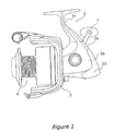
- Figure 1 is a side elevational view of a spinning reel equipped with a handle assembly in accordance with a first embodiment of the present invention
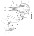
- Figure 2 is a side cross-sectional view of the spinning reel illustrated in Figure 1 in accordance with the first embodiment of the present invention
- FIG 3 is a rear plan view of the spinning reel and handle assembly illustrated in Figure 1 in accordance with the first embodiment of the present invention
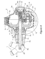
- Figure 4 is a partial rear cross-sectional view of the spinning reel and handle assembly illustrated in Figure 3 in accordance with the first embodiment of the present invention
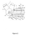
- FIG. 5 is a partial cross-sectional view of the handle assembly illustrated in Figures 3 and 4 in accordance with the first embodiment of the present invention
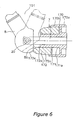
- Figure 6 is a partial cross-sectional view of a handle assembly for the spinning reel illustrated in Figures 1 and 2 in accordance with a second embodiment of the present invention
- Figure 7 is a partial cross-sectional view of a handle assembly for the spinning reel illustrated in Figures 1 and 2 in accordance with a third embodiment of the present invention.
- Figure 8 is a partial cross-sectional view of a handle assembly for the spinning reel illustrated in Figures 1 and 2 in accordance with a fourth embodiment of the present invention.
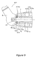
- Figure 9 is a partial cross-sectional view of a handle assembly for the spinning reel illustrated in Figures 1 and 2 in accordance with a fifth embodiment of the present invention.
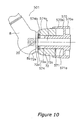
- Figure 10 is a partial cross-sectional view of a handle assembly for the spinning reel illustrated in Figures 1 and 2 in accordance with a sixth embodiment of the present invention
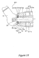
- FIG 11 is a partial cross-sectional view of a handle assembly for the spinning reel illustrated in Figures 1 and 2 in accordance with a seventh embodiment of the present invention.
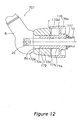
- Figure 12 is a partial cross-sectional view of a handle assembly for the spinning reel illustrated in Figures 1 and 2 in accordance with an eighth embodiment of the present invention.
- the spinning reel includes a handle assembly 1, a reel unit 2, a rotor 3 and a spool 4.
- the handle assembly 1 is supported on the reel unit 2 in a freely rotatable manner.
- the rotor 3 is rotatably supported on a frontward portion of the reel unit 2.
- the spool 4 supports a fishing line, which is wound around an outer periphery of the spool 4.
- the spool 4 is rotatably supported on a frontward portion of the reel unit 2.
- the handle assembly 1 is selectively mounted on either a right side (see Figures 1 and 2) or a left side (see Figures 3 and 4) of the reel unit 2.
- a bottomed cylindrical cap member 19 is attached to the side of the reel unit 2 opposite the side on which the handle assembly 1 is mounted (e.g., on the right side of the reel unit 2 in Figures 3 and 4).
- the handle assembly 1 includes a handle shaft portion 7, a handle arm 8 and a handle grip 9 that is mounted to a tip end of the handle arm 8.
- the handle arm 8 is mounted such that it extends in a radial direction from a tip end section of the handle shaft portion 7.
- the handle arm 8 pivots relative to the handle shaft portion 7.
- the handle assembly 1 further includes a cylindrical cover member 70, a cylindrical screw-threaded member 71, a cylindrical movable member 72 and a second ring-shaped member 73.
- the cylindrical cover member 70 is mounted on the external circumference of the tip end section of the handle shaft portion 7.
- the cylindrical cover member 70 is configured to cover the outside of the tip end section of the handle shaft portion 7.
- the cylindrical screw-threaded member 71 is arranged on the external circumference of the tip end section of the handle shaft portion 7 in a non-rotatably manner relative to the handle shaft portion 7.
- the movable member 72 is arranged inside the internal circumference of the cover member 70.
- a rotor drive mechanism 5 has a master gear shaft 10, a master gear 11 and a pinion gear 12.
- the pinion gear 12 meshes with the master gear 11.
- the master gear 11 rotates together with the master gear shaft 10.
- the master gear shaft 10 is a cylindrical member formed as a one-piece unitary member with the master gear 11.
- the master gear shaft 10 is rotatably supported on the reel unit 2 by first and second bearings 16 and 17 mounted inside the first and second boss sections 2e and 2f that protrude from both sides of the reel unit 2.
- the pinion gear 12 is a cylindrical member that passes through a center portion of the rotor 3.
- the pinion gear 12 has a front section 12a that is fastened to the rotor 3 with a nut 13.
- the pinion gear 12 further has middle and rear sections that are rotatably supported on the reel unit 2 by third and fourth bearings 14a and 14b.
- the master gear shaft 10 has a through hole 10a with an internal shape that is rectangular or another non-circular shape.
- the reel unit 2 has a reel body 2a, a lid member 2b, a fishing rod mounting leg 2c, a cover member 2d, first and second bosses 2e and 2f and an end cylindrical section 2g.
- the lid member 2b is detachably mounted to the reel body 2a in such a fashion as to block an opening of the reel body 2a.
- the reel body 2a is generally hollow.
- the fishing rod mounting leg 2c is configured to extend diagonally frontward and upward from the lid member 2b.
- the cover member 2d is configured and arranged to span from a rearward portion to a lower portion of the reel body 2a and the lid member 2b.
- the rotor drive mechanism 5 is configured to rotationally interlock the rotor 3 with the handle assembly 1.
- An oscillating mechanism 6 is configured to move the spool 4 in order to wind the fishing line in a uniform manner.
- the handle shaft portion 7 has a non-circular (e.g., rectangular) external shape.
- the handle shaft portion 7 is mounted to the through hole 10a of the master gear shaft 10.
- a tip end section of the handle shaft portion 7 protrudes to the outside of an end part of the master gear shaft 10.
- the handle shaft portion 7 is axially movable in the through hole 10a.
- the handle shaft portion 7 has a female threaded section 7a that is formed inside an end part (right end in Figure 4) of the handle shaft portion 7.
- a bolt member 18 having a male threaded section 18a is threaded into the female threaded section 7a of the handle shaft portion 7.
- the handle shaft portion 7 is secured to the master gear shaft 10.
- the handle arm 8 is a rod-like member made of, for example, an aluminum alloy.
- the handle arm 8 is formed to bend slightly toward the reel unit 2.
- One end (lower end in Figure 3) of the handle arm 8 is connected to the tip end section (left end in Figure 3) of the handle shaft portion 7 with a pin member 20 such that the reel unit 2 can pivot toward and away from the reel unit 2.
- the handle grip 9 of the handle assembly 1 is rotatably mounted to the other end (upper end in Figure 3) of the handle arm 8.
- the handle grip 9 includes a grip part 9a and a shaft portion 9b.
- the shaft portion 9b is mounted to the handle arm 8 such that it is able to freely rotate about an axis substantially parallel to the handle shaft portion 7.
- the grip part 9a is fixed to an end of the shaft portion 9b.
- the grip part 9a serves as a place for a fisherman to grip the handle assembly 1.
- the grip part 9a is made of, for example, a synthetic resin or cork material.
- the shaft portion 9b is made of, for example, a metal material.
- the cover member 70 is provided as a separate member from the handle shaft portion 7.
- the cover member 70 is mounted to the handle shaft portion 7 by insert molding such that it cannot rotate relative to the handle shaft portion 7. It will be apparent to one of ordinary skill in the art from this disclosure that although the cover member 70 is formed by insert molding with the handle shaft portion 7 in the embodiment, the present invention is not limited to such method and it is also acceptable to form the cover member 70 and the handle shaft portion 7 as a one-piece unitary member.
- the cover member 70 has first and second cylindrical sections 70a and 70b, a cylindrical cover part 70c and a staking recession 70d.
- the first cylindrical section 70a is configured to cover an outside of the end cylindrical section 2g (see Figure 4) of the second boss section 2f that supports an end part of the master gear shaft 10.
- the second cylindrical section 70b is configured to protrude in an opposite direction as the first cylindrical section 70a.
- the cover part 70c inwardly protrudes toward the end cylindrical section 2g (see Figure 4) from within the internal circumference of the first cylindrical section 70a.
- the second ring-shaped member 73 is installed inside the cover part 70c and arranged such that a tip end thereof touches against the end part of the master gear shaft 10.
- a portion of the cover member 70 is recessed along an axial direction from the internal circumference of the second cylindrical section 70b.
- the screw-threaded member 71 is a cylindrical member having a male threaded section 71a and a staking protrusion 71b.
- the male threaded section 71a is formed on the external circumference of the screw-threaded member 71.
- the male threaded section 71a is provided as a separate entity from the cover member 70.
- the staking protrusion 71b is formed on the rearward end (right end in Figure 5) of the screw-threaded member 71.
- the staking protrusion 71b serves to stake or secure the screw-threaded member 71 to the cover member 70 by being inserted into the staking recession 70d.
- the cover member 70 is configured to cover at least a portion of the outside circumference of the movable member 72 and the entire outside circumference of the portion of the male threaded section 71a on which the movable member 72 is not mounted.
- the movable member 72 is a cylindrical member that includes a countersink section 72b and a main body member 72c having a female threaded section 72a formed on an internal section thereof.
- the female threaded section 72a of the movable member 72 is threaded onto the male threaded section 71a.
- the countersink section 72b is formed by countersinking a tip end (left end in Figure 5) of the main body member 72c to a diameter that is larger than a diameter of the female threaded section 72a.
- a first force applying member 74 is, a belleville spring, for example, that is installed into the countersink section 72b.
- the first force applying member 74 applies a force against the main body member 72c and prevents the main body member 72c from loosening.
- the movable member 72 further includes a first ring-shaped member 72d that is a separate member from the main body member 72c.
- the first ring-shaped member 72d is mounted such that it contacts the tip end of the main body member 72c.
- the first ring-shaped member 72d is biased toward the handle arm 8 by the first force applying member 74.
- the handle arm 8 has a contact part 8a that is configured to restrict pivoting when it contacts an end face 72e of the first ring-shaped member 72d (see lower portion of Figure 5) and to allow pivoting when the contact part 8a is separated from the end face 72e (see upper portion of Figure 5).
- the movable member 72 is rotated in a tightening direction, as shown in Figures 4 and 5, such that the female threaded section 72a screws onto the male threaded section 71a of the screw-threaded member 71 and the screw-threaded member 72 moves toward the reel unit 2 (to the right in Figures 4 and 5).
- the end face 72e separates from the contact part 8a and a gap develops between the movable member 72 and the handle arm 8, thereby enabling the handle arm 8 to be folded over toward the reel unit 2 (see upper portion of Figure 5).
- the movable member 72 In order to pivot the handle arm 8 to such a position that it can be rotated, the movable member 72 is rotated in the loosening direction as shown in Figures 4 and 5 such that the female threaded section 72a screws off of the male threaded section 71a of the screw-threaded member 71 and the screw-threaded member 72 moves away from the reel unit 2 (to the left in Figures 4 and 5).
- the end face 72e of the first ring-shaped member 72d of the movable member 72 contacts the contact part 8a of the handle arm 8 and the handle arm 8 becomes unable to pivot with respect to the movable member 72 and able to be rotated (see lower portion of Figure 5).
- the oscillating mechanism 6 is configured to move a spool shaft 15.
- the spool shaft 15 passes through a center of the spool 4 and connects to a drag mechanism 60.
- the spool 4 moves along the spool shaft 15 with the drag mechanism 60.
- the oscillating mechanism 6 has a helical shaft 21, a slider 22 and an intermediate gear 23.
- the helical shaft 21 is arranged below and parallel to the spool shaft 15.
- the slider 22 is fastened in a non-rotatable manner to a rear end of the spool shaft 15.
- the slider 22 is configured to move along the helical shaft 21.
- the intermediate gear 23 is fixed to a tip end of the helical shaft 21.
- the intermediate gear 23 meshes with the pinion gear 12 via a reduction gear mechanism (not shown).
- the reduction gear mechanism enables the oscillating mechanism 6 to oscillate slowly so that the fishing line is wound onto the spool 4 in a precise manner.
- the rotor 3 has a cylindrical part 30, first and second rotor arms 31 and 32, a front wall 33 and a bail arm 44.
- the first and second rotor arms 31 and 32 are arranged to face each other on opposite sides of the cylindrical part 30.
- the cylindrical part 30 and the first and second rotor arms 31 and 32 are formed as a one-piece unitary member.
- the front wall 33 is formed on a front portion of the cylindrical part 30.
- the front wall 33 has a boss section 33a that is provided at a middle portion of the front wall 33.
- the boss section 33a has a through hole formed in a center thereof.
- the spool shaft 15 and the front section of the pinion gear 12 pass through the through hole of the boss section 33a.
- the nut 13 is disposed on the front portion of the front wall 33 and serves to fasten the front section 12a of the pinion gear 12 to the rotor 3.
- the first rotor arm 31 curves convexly outward from the cylindrical part 30 and extends forward.
- the bail arm 44 includes a first bail support member 40, a second bail support member 42, a line roller 41 and a bail 43.
- the first bail support member 40 is mounted pivotally to an outer circumference of a tip end of the first rotor arm 31.
- the line roller 41 guides the fishing line to the spool 4.
- the line roller 41 is mounted on a tip end of the first bail support member 40.
- the second rotor arm 32 curves convexly outward from the cylindrical part 30 and extends forward.
- the second bail support member 42 is mounted pivotally to an outer circumference of a tip end of the second rotor arm 32.
- the bail 43 has a wire material bent into a U-shape.
- the bail 43 is fixed between the line roller 41 and the second bail support member 42.
- the bail arm 44 is configured such that it pivots freely between a line guiding position shown in Figure 2 and a line
- a reverse rotation preventing mechanism 50 for selectively prohibiting and allowing reverse rotation of the rotor 3 is arranged inside the cylindrical part 30 of the rotor 3.
- the reverse rotation preventing mechanism 50 includes a roller-type one-way clutch 51 having a freely rotating inner ring and a switching mechanism 52 configured to switch the one-way clutch between an engaged state (reverse rotation prohibited) and a disengaged state (reverse rotational allowed).
- the spool 4 is arranged between the first rotor arm 31 and the second rotor arm 32 of the rotor 3 and mounted to the tip end of the spool shaft 15 via the drag mechanism 60.
- the cover member 70 of the handle assembly 1 covers at least a portion of the outside circumference of the movable member 72 and the entire outside circumference of the portion of the male threaded section 71a on which the movable member 72 is not mounted, the male threaded section 71a is always covered by either the cover member 70 or the movable member 72 regardless of the position of the movable member 72. As a result, the male threaded section 71a is never exposed to the outside.
- the present invention can also be applied to other spinning reels, such as a spinning reel having both a front drag mechanism and a lever drag mechanism.
- a handle assembly 101 in accordance with a second embodiment will now be explained.
- the parts of the second embodiment that are identical to the parts of the first embodiment will be given the same reference numerals as the parts of the first embodiment.
- the descriptions of the parts of the second embodiment that are identical to the parts of the first embodiment may be omitted for the sake of brevity.
- the movable member 72 has a main body member 72c and a separate first ring member 72d.
- a movable member 172 does not have the separate first ring member 72d.
- the movable member 172 has an end face 172e of a main body member 172c that contacts the contact part 8a of the handle arm 8 directly, as shown in Figure 6.
- cover member 70 and the screw-threaded member 71 are separate members.
- a cover member 170 and a screw-threaded member 171 are formed as a one-piece unitary member, as shown in Figure 6.
- a handle assembly 201 in accordance with a third embodiment will now be explained.
- the parts of the third embodiment that are identical to the parts of the second embodiment will be given the same reference numerals as the parts of the second embodiment.
- the descriptions of the parts of the third embodiment that are identical to the parts of the second embodiment may be omitted for the sake of brevity.
- a moveable member 272 has a groove for an elastic member 276, e.g., an O-ring.
- the elastic member 276 is disposed in the groove between an internal circumference of the cover member 170 and an external circumference of the movable member 272, as shown in Figure 7.
- a handle assembly 301 in accordance with a fourth embodiment will now be explained.
- the parts of the fourth embodiment that are identical to the parts of the second embodiment will be given the same reference numerals as the parts of the second embodiment.
- the descriptions of the parts of the fourth embodiment that are identical to the parts of the second embodiment may be omitted for the sake of brevity.
- a second force applying member 375 e.g., a coil spring, is provided between the cover member 170 and the movable member 172, as shown in Figure 8.
- the second force applying member 375 By providing the second force applying member 375, the movable member 172 is loaded toward the handle arm 8 and undesirable looseness of the movable member 172 is suppressed.
- a handle assembly 401 in accordance with a fifth embodiment will now be explained.
- the parts of the fifth embodiment that are identical to the parts of the first embodiment will be given the same reference numerals as the parts of the first embodiment.
- the descriptions of the parts of the fifth embodiment that are identical to the parts of the first embodiment may be omitted for the sake of brevity.
- the first force applying member 74 included a belleville spring provided between the movable member 72 and the handle arm 8.
- two belleville springs 474a are used as a first force applying member 474, as shown in Figure 9.
- cover member 70 and the screw-threaded member 71 are separate members.
- a cover member 470 and a screw-threaded member 471 are formed as a one-piece unitary member, as shown in Figure 9.
- a handle assembly 501 in accordance with a sixth embodiment will now be explained.
- the parts of the sixth embodiment that are identical to the parts of the first embodiment will be given the same reference numerals as the parts of the first embodiment.
- the descriptions of the parts of the sixth embodiment that are identical to the parts of the first embodiment may be omitted for the sake of brevity.
- the first force applying member 74 included a belleville spring provided between the movable member 72 and the handle arm 8.
- a toothed washer 574b and a third ring-shaped member 574c made of a synthetic resin material are provided as a first force applying member 574, as shown in Figure 10.
- cover member 70 and the screw-threaded member 71 are separate members.
- a cover member 570 and a screw-threaded member 571 are formed as a one-piece unitary member, as shown in Figure 10.
- a handle assembly 601 in accordance with a seventh embodiment will now be explained.
- the parts of the seventh embodiment that are identical to the parts of the first embodiment will be given the same reference numerals as the parts of the first embodiment.
- the descriptions of the parts of the seventh embodiment that are identical to the parts of the first embodiment may be omitted for the sake of brevity.
- the first force applying member 74 included a belleville spring provided between the movable member 72 and the handle arm 8.
- a toothed washer 674b, a third ring-shaped member 674c made of a synthetic resin material, and one belleville spring 674a are provided as a force applying member 674, as shown in Figure 11. Since the force applying member 674 loads the movable member 72 toward the handle arm 8, undesirable looseness of the movable member 72 is suppressed.
- cover member 70 and the screw-threaded member 71 are separate members.
- a cover member 670 and a screw-threaded member 671 are formed as a one-piece unitary member, as shown in Figure 11.
- a handle assembly 701 in accordance with an eighth embodiment will now be explained.
- the parts of the eighth embodiment that are identical to the parts of the second embodiment will be given the same reference numerals as the parts of the second embodiment.
- the descriptions of the parts of the eighth embodiment that are identical to the parts of the second embodiment may be omitted for the sake of brevity.
- a bushing member 777 is arranged between the cover member 170 and the master gear shaft 10.
- the bushing member 777 is configured such that an external circumference of the bushing member 777 tapers from the cover member 170 toward the master gear shaft 10.
Landscapes
- Life Sciences & Earth Sciences (AREA)
- Environmental Sciences (AREA)
- Animal Husbandry (AREA)
- Biodiversity & Conservation Biology (AREA)
- Fishing Rods (AREA)
Applications Claiming Priority (1)
| Application Number | Priority Date | Filing Date | Title |
|---|---|---|---|
| JP2005033605A JP2006217848A (ja) | 2005-02-09 | 2005-02-09 | スピニングリールのハンドル組立体 |
Publications (2)
| Publication Number | Publication Date |
|---|---|
| EP1690452A1 EP1690452A1 (en) | 2006-08-16 |
| EP1690452B1 true EP1690452B1 (en) | 2007-06-13 |
Family
ID=36202565
Family Applications (1)
| Application Number | Title | Priority Date | Filing Date |
|---|---|---|---|
| EP06250731A Not-in-force EP1690452B1 (en) | 2005-02-09 | 2006-02-09 | Spinning reel handle assembly |
Country Status (10)
| Country | Link |
|---|---|
| US (1) | US7163168B2 (enExample) |
| EP (1) | EP1690452B1 (enExample) |
| JP (1) | JP2006217848A (enExample) |
| KR (1) | KR20060090574A (enExample) |
| CN (1) | CN1817122B (enExample) |
| AT (1) | ATE364313T1 (enExample) |
| DE (1) | DE602006000019T2 (enExample) |
| MY (1) | MY138329A (enExample) |
| SG (1) | SG125179A1 (enExample) |
| TW (1) | TW200638870A (enExample) |
Families Citing this family (10)
| Publication number | Priority date | Publication date | Assignee | Title |
|---|---|---|---|---|
| JP4804279B2 (ja) * | 2006-08-31 | 2011-11-02 | 株式会社シマノ | スピニングリール |
| JP4901500B2 (ja) * | 2007-01-23 | 2012-03-21 | 株式会社シマノ | 両軸受リールのハンドル軸支持構造 |
| JP5236883B2 (ja) * | 2007-02-13 | 2013-07-17 | シマノコンポネンツ マレーシア エスディーエヌ.ビーエッチディー. | スピニングリールのハンドル組立体 |
| JP5624069B2 (ja) * | 2012-01-23 | 2014-11-12 | シマノコンポネンツ マレーシア エスディーエヌ.ビーエッチディー. | スピニングリール及びスピニングリールのドラグ切換装置 |
| US9332744B2 (en) * | 2012-05-29 | 2016-05-10 | Globeride, Inc. | Fishing spinning reel |
| JP6027805B2 (ja) * | 2012-07-24 | 2016-11-16 | 株式会社シマノ | スピニングリールのハンドル組立体 |
| JP6227891B2 (ja) * | 2013-04-30 | 2017-11-08 | 株式会社シマノ | 釣り用リール |
| JP6352618B2 (ja) * | 2013-11-19 | 2018-07-04 | 株式会社シマノ | スピニングリール |
| JP6505405B2 (ja) * | 2014-09-26 | 2019-04-24 | シマノコンポネンツ マレーシア エスディーエヌ.ビーエッチディー. | ハンドル組立体 |
| US10219498B2 (en) | 2016-08-29 | 2019-03-05 | Pure Fishing, Inc. | Reel with disengageable seal |
Family Cites Families (16)
| Publication number | Priority date | Publication date | Assignee | Title |
|---|---|---|---|---|
| US2766956A (en) * | 1955-03-29 | 1956-10-16 | Enterprise Mfg Co | Salt water spinning reel |
| US3948117A (en) * | 1973-11-07 | 1976-04-06 | Shimano Industrial Company, Limited | Operating handle of a fishing reel |
| JPS53130195U (enExample) * | 1977-03-23 | 1978-10-16 | ||
| JPS53130195A (en) * | 1977-04-15 | 1978-11-13 | Tokyo Kyuei Kk | Structure of ground for culture and propagation of fish and shellfishes etc |
| JPS53149591A (en) * | 1977-05-31 | 1978-12-27 | Matsuo Kogyo | Handle folding mechanism of angling reel apparatus |
| GB2023983A (en) * | 1978-06-29 | 1980-01-09 | Intrepid Sealey Ltd | Folding handle and fishing reel incorporating it |
| JPS5977364U (ja) * | 1982-11-11 | 1984-05-25 | 株式会社シマノ | 釣用リ−ル |
| US5244166A (en) * | 1989-11-20 | 1993-09-14 | Shimano, Inc. | Handle fixing structure for spinning reel |
| EP0641514B1 (en) * | 1993-09-08 | 1998-01-07 | Daiwa Seiko Inc. | Handle mounting structure in fishing reel |
| JP3964623B2 (ja) * | 2001-01-18 | 2007-08-22 | ダイワ精工株式会社 | 魚釣用リールのハンドル |
| JP3947383B2 (ja) * | 2001-10-25 | 2007-07-18 | 株式会社シマノ | スピニングリール |
| JP4045167B2 (ja) * | 2002-05-01 | 2008-02-13 | 株式会社シマノ | スピニングリールのハンドル組立体 |
| US6626385B1 (en) * | 2002-08-01 | 2003-09-30 | Daiwa Seiko, Inc. | Spinning reel for fishing |
| JP3956359B2 (ja) * | 2002-09-17 | 2007-08-08 | ダイワ精工株式会社 | 魚釣用スピニングリール |
| JP4015957B2 (ja) * | 2003-01-20 | 2007-11-28 | 株式会社シマノ | スピニングリールのハンドル組立体 |
| JP2005253372A (ja) * | 2004-03-12 | 2005-09-22 | Daiwa Seiko Inc | 魚釣用リールのハンドル |
-
2005
- 2005-02-09 JP JP2005033605A patent/JP2006217848A/ja active Pending
-
2006
- 2006-01-19 SG SG200600386A patent/SG125179A1/en unknown
- 2006-01-20 KR KR1020060006179A patent/KR20060090574A/ko not_active Withdrawn
- 2006-01-24 MY MYPI20060308A patent/MY138329A/en unknown
- 2006-01-25 TW TW095102905A patent/TW200638870A/zh unknown
- 2006-02-08 US US11/349,528 patent/US7163168B2/en not_active Expired - Fee Related
- 2006-02-09 AT AT06250731T patent/ATE364313T1/de not_active IP Right Cessation
- 2006-02-09 EP EP06250731A patent/EP1690452B1/en not_active Not-in-force
- 2006-02-09 CN CN2006100071549A patent/CN1817122B/zh not_active Expired - Fee Related
- 2006-02-09 DE DE602006000019T patent/DE602006000019T2/de active Active
Non-Patent Citations (1)
| Title |
|---|
| None * |
Also Published As
| Publication number | Publication date |
|---|---|
| KR20060090574A (ko) | 2006-08-14 |
| US7163168B2 (en) | 2007-01-16 |
| EP1690452A1 (en) | 2006-08-16 |
| CN1817122B (zh) | 2011-07-27 |
| MY138329A (en) | 2009-05-29 |
| JP2006217848A (ja) | 2006-08-24 |
| ATE364313T1 (de) | 2007-07-15 |
| CN1817122A (zh) | 2006-08-16 |
| DE602006000019T2 (de) | 2008-02-21 |
| US20060175448A1 (en) | 2006-08-10 |
| DE602006000019D1 (de) | 2007-07-26 |
| TW200638870A (en) | 2006-11-16 |
| SG125179A1 (en) | 2006-09-29 |
Similar Documents
| Publication | Publication Date | Title |
|---|---|---|
| EP1690452B1 (en) | Spinning reel handle assembly | |
| US7314192B2 (en) | Spinning reel | |
| KR101396775B1 (ko) | 스피닝 릴의 핸들 조립체 | |
| EP1304032B1 (en) | Fastening structure for fishing equipment parts | |
| KR101488151B1 (ko) | 낚시용 릴의 핸들 손잡이 | |
| US6883738B2 (en) | Spinning reel handle assembly | |
| US7150423B2 (en) | Reel unit for a dual bearing reel | |
| JP3585373B2 (ja) | 部品組立体 | |
| JP3372809B2 (ja) | スピニングリールのフレーム構造 | |
| US20040079822A1 (en) | Spool for dual-bearing reel | |
| US20040140385A1 (en) | Handle assembly for a spinning reel | |
| US7137585B2 (en) | Fishing line guide mechanism for a spinning reel | |
| JP2006217848A5 (enExample) | ||
| US7097124B2 (en) | Dual bearing reel | |
| US7066419B2 (en) | Reel unit for spinning reel | |
| EP1302105B1 (en) | Fishing line guiding mechanism for spinning reel | |
| EP1407662B1 (en) | Fishing line guide mechanism for spinning reel | |
| KR20040071073A (ko) | 스피닝 릴의 릴 본체 | |
| US7104484B2 (en) | Drag mechanism for a dual bearing reel | |
| US7077349B2 (en) | Fishing line guide mechanism for spinning reel | |
| JP2001028980A (ja) | スピニングリールのロータ | |
| JP4427279B2 (ja) | 釣り用リールのトグルばね機構 | |
| JP2003259774A (ja) | 釣り用リールのハンドル取付構造 | |
| JP2006271312A (ja) | 魚釣用スピニングリール | |
| KR20040071057A (ko) | 스피닝 릴의 로터 회전 규제 장치 |
Legal Events
| Date | Code | Title | Description |
|---|---|---|---|
| PUAI | Public reference made under article 153(3) epc to a published international application that has entered the european phase |
Free format text: ORIGINAL CODE: 0009012 |
|
| AK | Designated contracting states |
Kind code of ref document: A1 Designated state(s): AT BE BG CH CY CZ DE DK EE ES FI FR GB GR HU IE IS IT LI LT LU LV MC NL PL PT RO SE SI SK TR |
|
| AX | Request for extension of the european patent |
Extension state: AL BA HR MK YU |
|
| 17P | Request for examination filed |
Effective date: 20060907 |
|
| GRAP | Despatch of communication of intention to grant a patent |
Free format text: ORIGINAL CODE: EPIDOSNIGR1 |
|
| AKX | Designation fees paid |
Designated state(s): AT BE BG CH CY CZ DE DK EE ES FI FR GB GR HU IE IS IT LI LT LU LV MC NL PL PT RO SE SI SK TR |
|
| GRAS | Grant fee paid |
Free format text: ORIGINAL CODE: EPIDOSNIGR3 |
|
| GRAA | (expected) grant |
Free format text: ORIGINAL CODE: 0009210 |
|
| AK | Designated contracting states |
Kind code of ref document: B1 Designated state(s): AT BE BG CH CY CZ DE DK EE ES FI FR GB GR HU IE IS IT LI LT LU LV MC NL PL PT RO SE SI SK TR |
|
| PG25 | Lapsed in a contracting state [announced via postgrant information from national office to epo] |
Ref country code: CH Free format text: LAPSE BECAUSE OF FAILURE TO SUBMIT A TRANSLATION OF THE DESCRIPTION OR TO PAY THE FEE WITHIN THE PRESCRIBED TIME-LIMIT Effective date: 20070613 Ref country code: LI Free format text: LAPSE BECAUSE OF FAILURE TO SUBMIT A TRANSLATION OF THE DESCRIPTION OR TO PAY THE FEE WITHIN THE PRESCRIBED TIME-LIMIT Effective date: 20070613 |
|
| REG | Reference to a national code |
Ref country code: GB Ref legal event code: FG4D |
|
| REG | Reference to a national code |
Ref country code: CH Ref legal event code: EP |
|
| REG | Reference to a national code |
Ref country code: IE Ref legal event code: FG4D |
|
| REF | Corresponds to: |
Ref document number: 602006000019 Country of ref document: DE Date of ref document: 20070726 Kind code of ref document: P |
|
| PG25 | Lapsed in a contracting state [announced via postgrant information from national office to epo] |
Ref country code: SE Free format text: LAPSE BECAUSE OF FAILURE TO SUBMIT A TRANSLATION OF THE DESCRIPTION OR TO PAY THE FEE WITHIN THE PRESCRIBED TIME-LIMIT Effective date: 20070913 |
|
| PG25 | Lapsed in a contracting state [announced via postgrant information from national office to epo] |
Ref country code: PL Free format text: LAPSE BECAUSE OF FAILURE TO SUBMIT A TRANSLATION OF THE DESCRIPTION OR TO PAY THE FEE WITHIN THE PRESCRIBED TIME-LIMIT Effective date: 20070613 Ref country code: AT Free format text: LAPSE BECAUSE OF FAILURE TO SUBMIT A TRANSLATION OF THE DESCRIPTION OR TO PAY THE FEE WITHIN THE PRESCRIBED TIME-LIMIT Effective date: 20070613 |
|
| NLV1 | Nl: lapsed or annulled due to failure to fulfill the requirements of art. 29p and 29m of the patents act | ||
| REG | Reference to a national code |
Ref country code: CH Ref legal event code: PL |
|
| PG25 | Lapsed in a contracting state [announced via postgrant information from national office to epo] |
Ref country code: BE Free format text: LAPSE BECAUSE OF FAILURE TO SUBMIT A TRANSLATION OF THE DESCRIPTION OR TO PAY THE FEE WITHIN THE PRESCRIBED TIME-LIMIT Effective date: 20070613 |
|
| PG25 | Lapsed in a contracting state [announced via postgrant information from national office to epo] |
Ref country code: NL Free format text: LAPSE BECAUSE OF FAILURE TO SUBMIT A TRANSLATION OF THE DESCRIPTION OR TO PAY THE FEE WITHIN THE PRESCRIBED TIME-LIMIT Effective date: 20070613 Ref country code: CZ Free format text: LAPSE BECAUSE OF FAILURE TO SUBMIT A TRANSLATION OF THE DESCRIPTION OR TO PAY THE FEE WITHIN THE PRESCRIBED TIME-LIMIT Effective date: 20070613 Ref country code: PT Free format text: LAPSE BECAUSE OF FAILURE TO SUBMIT A TRANSLATION OF THE DESCRIPTION OR TO PAY THE FEE WITHIN THE PRESCRIBED TIME-LIMIT Effective date: 20071113 Ref country code: IS Free format text: LAPSE BECAUSE OF FAILURE TO SUBMIT A TRANSLATION OF THE DESCRIPTION OR TO PAY THE FEE WITHIN THE PRESCRIBED TIME-LIMIT Effective date: 20071013 Ref country code: BG Free format text: LAPSE BECAUSE OF FAILURE TO SUBMIT A TRANSLATION OF THE DESCRIPTION OR TO PAY THE FEE WITHIN THE PRESCRIBED TIME-LIMIT Effective date: 20070913 Ref country code: ES Free format text: LAPSE BECAUSE OF FAILURE TO SUBMIT A TRANSLATION OF THE DESCRIPTION OR TO PAY THE FEE WITHIN THE PRESCRIBED TIME-LIMIT Effective date: 20070924 Ref country code: SI Free format text: LAPSE BECAUSE OF FAILURE TO SUBMIT A TRANSLATION OF THE DESCRIPTION OR TO PAY THE FEE WITHIN THE PRESCRIBED TIME-LIMIT Effective date: 20070613 |
|
| EN | Fr: translation not filed | ||
| PG25 | Lapsed in a contracting state [announced via postgrant information from national office to epo] |
Ref country code: LT Free format text: LAPSE BECAUSE OF FAILURE TO SUBMIT A TRANSLATION OF THE DESCRIPTION OR TO PAY THE FEE WITHIN THE PRESCRIBED TIME-LIMIT Effective date: 20070613 Ref country code: LV Free format text: LAPSE BECAUSE OF FAILURE TO SUBMIT A TRANSLATION OF THE DESCRIPTION OR TO PAY THE FEE WITHIN THE PRESCRIBED TIME-LIMIT Effective date: 20070613 Ref country code: SK Free format text: LAPSE BECAUSE OF FAILURE TO SUBMIT A TRANSLATION OF THE DESCRIPTION OR TO PAY THE FEE WITHIN THE PRESCRIBED TIME-LIMIT Effective date: 20070613 |
|
| PLBE | No opposition filed within time limit |
Free format text: ORIGINAL CODE: 0009261 |
|
| STAA | Information on the status of an ep patent application or granted ep patent |
Free format text: STATUS: NO OPPOSITION FILED WITHIN TIME LIMIT |
|
| PG25 | Lapsed in a contracting state [announced via postgrant information from national office to epo] |
Ref country code: GR Free format text: LAPSE BECAUSE OF FAILURE TO SUBMIT A TRANSLATION OF THE DESCRIPTION OR TO PAY THE FEE WITHIN THE PRESCRIBED TIME-LIMIT Effective date: 20070914 Ref country code: DK Free format text: LAPSE BECAUSE OF FAILURE TO SUBMIT A TRANSLATION OF THE DESCRIPTION OR TO PAY THE FEE WITHIN THE PRESCRIBED TIME-LIMIT Effective date: 20070613 |
|
| 26N | No opposition filed |
Effective date: 20080314 |
|
| PG25 | Lapsed in a contracting state [announced via postgrant information from national office to epo] |
Ref country code: RO Free format text: LAPSE BECAUSE OF FAILURE TO SUBMIT A TRANSLATION OF THE DESCRIPTION OR TO PAY THE FEE WITHIN THE PRESCRIBED TIME-LIMIT Effective date: 20070613 |
|
| PG25 | Lapsed in a contracting state [announced via postgrant information from national office to epo] |
Ref country code: FR Free format text: LAPSE BECAUSE OF FAILURE TO SUBMIT A TRANSLATION OF THE DESCRIPTION OR TO PAY THE FEE WITHIN THE PRESCRIBED TIME-LIMIT Effective date: 20080208 |
|
| PG25 | Lapsed in a contracting state [announced via postgrant information from national office to epo] |
Ref country code: MC Free format text: LAPSE BECAUSE OF NON-PAYMENT OF DUE FEES Effective date: 20080228 |
|
| PG25 | Lapsed in a contracting state [announced via postgrant information from national office to epo] |
Ref country code: IE Free format text: LAPSE BECAUSE OF NON-PAYMENT OF DUE FEES Effective date: 20080211 Ref country code: EE Free format text: LAPSE BECAUSE OF FAILURE TO SUBMIT A TRANSLATION OF THE DESCRIPTION OR TO PAY THE FEE WITHIN THE PRESCRIBED TIME-LIMIT Effective date: 20070613 |
|
| PG25 | Lapsed in a contracting state [announced via postgrant information from national office to epo] |
Ref country code: FI Free format text: LAPSE BECAUSE OF FAILURE TO SUBMIT A TRANSLATION OF THE DESCRIPTION OR TO PAY THE FEE WITHIN THE PRESCRIBED TIME-LIMIT Effective date: 20070613 |
|
| PG25 | Lapsed in a contracting state [announced via postgrant information from national office to epo] |
Ref country code: CY Free format text: LAPSE BECAUSE OF FAILURE TO SUBMIT A TRANSLATION OF THE DESCRIPTION OR TO PAY THE FEE WITHIN THE PRESCRIBED TIME-LIMIT Effective date: 20070613 |
|
| PGFP | Annual fee paid to national office [announced via postgrant information from national office to epo] |
Ref country code: IT Payment date: 20100220 Year of fee payment: 5 |
|
| PG25 | Lapsed in a contracting state [announced via postgrant information from national office to epo] |
Ref country code: HU Free format text: LAPSE BECAUSE OF FAILURE TO SUBMIT A TRANSLATION OF THE DESCRIPTION OR TO PAY THE FEE WITHIN THE PRESCRIBED TIME-LIMIT Effective date: 20071214 Ref country code: LU Free format text: LAPSE BECAUSE OF NON-PAYMENT OF DUE FEES Effective date: 20080209 |
|
| PG25 | Lapsed in a contracting state [announced via postgrant information from national office to epo] |
Ref country code: TR Free format text: LAPSE BECAUSE OF FAILURE TO SUBMIT A TRANSLATION OF THE DESCRIPTION OR TO PAY THE FEE WITHIN THE PRESCRIBED TIME-LIMIT Effective date: 20070613 |
|
| PG25 | Lapsed in a contracting state [announced via postgrant information from national office to epo] |
Ref country code: IT Free format text: LAPSE BECAUSE OF NON-PAYMENT OF DUE FEES Effective date: 20110209 |
|
| PGFP | Annual fee paid to national office [announced via postgrant information from national office to epo] |
Ref country code: DE Payment date: 20150203 Year of fee payment: 10 |
|
| PGFP | Annual fee paid to national office [announced via postgrant information from national office to epo] |
Ref country code: GB Payment date: 20150204 Year of fee payment: 10 |
|
| REG | Reference to a national code |
Ref country code: DE Ref legal event code: R119 Ref document number: 602006000019 Country of ref document: DE |
|
| GBPC | Gb: european patent ceased through non-payment of renewal fee |
Effective date: 20160209 |
|
| PG25 | Lapsed in a contracting state [announced via postgrant information from national office to epo] |
Ref country code: DE Free format text: LAPSE BECAUSE OF NON-PAYMENT OF DUE FEES Effective date: 20160901 Ref country code: GB Free format text: LAPSE BECAUSE OF NON-PAYMENT OF DUE FEES Effective date: 20160209 |