EP1689558B1 - Verfahren und vorrichtung zur bearbeitung von platten - Google Patents
Verfahren und vorrichtung zur bearbeitung von platten Download PDFInfo
- Publication number
- EP1689558B1 EP1689558B1 EP04805273A EP04805273A EP1689558B1 EP 1689558 B1 EP1689558 B1 EP 1689558B1 EP 04805273 A EP04805273 A EP 04805273A EP 04805273 A EP04805273 A EP 04805273A EP 1689558 B1 EP1689558 B1 EP 1689558B1
- Authority
- EP
- European Patent Office
- Prior art keywords
- machining
- axis
- panel
- support
- holding element
- Prior art date
- Legal status (The legal status is an assumption and is not a legal conclusion. Google has not performed a legal analysis and makes no representation as to the accuracy of the status listed.)
- Expired - Lifetime
Links
- 238000003754 machining Methods 0.000 title claims abstract description 152
- 238000000034 method Methods 0.000 title claims abstract description 30
- 238000013519 translation Methods 0.000 claims description 42
- 239000000463 material Substances 0.000 claims description 12
- 238000013016 damping Methods 0.000 claims description 8
- 230000014759 maintenance of location Effects 0.000 claims description 2
- 230000014616 translation Effects 0.000 description 32
- 238000006073 displacement reaction Methods 0.000 description 24
- 239000002245 particle Substances 0.000 description 5
- 239000012530 fluid Substances 0.000 description 3
- 238000009434 installation Methods 0.000 description 3
- 239000000243 solution Substances 0.000 description 3
- 230000009747 swallowing Effects 0.000 description 3
- 238000004140 cleaning Methods 0.000 description 2
- 239000003344 environmental pollutant Substances 0.000 description 2
- 238000012423 maintenance Methods 0.000 description 2
- 238000004519 manufacturing process Methods 0.000 description 2
- 230000000873 masking effect Effects 0.000 description 2
- 238000012986 modification Methods 0.000 description 2
- 230000004048 modification Effects 0.000 description 2
- 231100000719 pollutant Toxicity 0.000 description 2
- 229910000831 Steel Inorganic materials 0.000 description 1
- 240000008042 Zea mays Species 0.000 description 1
- 238000010521 absorption reaction Methods 0.000 description 1
- 230000021615 conjugation Effects 0.000 description 1
- 238000001816 cooling Methods 0.000 description 1
- 238000012937 correction Methods 0.000 description 1
- 238000000354 decomposition reaction Methods 0.000 description 1
- 238000013461 design Methods 0.000 description 1
- 230000000694 effects Effects 0.000 description 1
- 230000005489 elastic deformation Effects 0.000 description 1
- 239000008151 electrolyte solution Substances 0.000 description 1
- 230000005484 gravity Effects 0.000 description 1
- 238000013507 mapping Methods 0.000 description 1
- 239000002184 metal Substances 0.000 description 1
- 229910052751 metal Inorganic materials 0.000 description 1
- 229910001092 metal group alloy Inorganic materials 0.000 description 1
- 238000003801 milling Methods 0.000 description 1
- 229920003023 plastic Polymers 0.000 description 1
- 239000004033 plastic Substances 0.000 description 1
- 238000011084 recovery Methods 0.000 description 1
- 238000004064 recycling Methods 0.000 description 1
- 238000005507 spraying Methods 0.000 description 1
- 239000010959 steel Substances 0.000 description 1
- 229920002994 synthetic fiber Polymers 0.000 description 1
- XLYOFNOQVPJJNP-UHFFFAOYSA-N water Substances O XLYOFNOQVPJJNP-UHFFFAOYSA-N 0.000 description 1
Images


Classifications
-
- B—PERFORMING OPERATIONS; TRANSPORTING
- B23—MACHINE TOOLS; METAL-WORKING NOT OTHERWISE PROVIDED FOR
- B23Q—DETAILS, COMPONENTS, OR ACCESSORIES FOR MACHINE TOOLS, e.g. ARRANGEMENTS FOR COPYING OR CONTROLLING; MACHINE TOOLS IN GENERAL CHARACTERISED BY THE CONSTRUCTION OF PARTICULAR DETAILS OR COMPONENTS; COMBINATIONS OR ASSOCIATIONS OF METAL-WORKING MACHINES, NOT DIRECTED TO A PARTICULAR RESULT
- B23Q1/00—Members which are comprised in the general build-up of a form of machine, particularly relatively large fixed members
- B23Q1/01—Frames, beds, pillars or like members; Arrangement of ways
-
- B—PERFORMING OPERATIONS; TRANSPORTING
- B23—MACHINE TOOLS; METAL-WORKING NOT OTHERWISE PROVIDED FOR
- B23Q—DETAILS, COMPONENTS, OR ACCESSORIES FOR MACHINE TOOLS, e.g. ARRANGEMENTS FOR COPYING OR CONTROLLING; MACHINE TOOLS IN GENERAL CHARACTERISED BY THE CONSTRUCTION OF PARTICULAR DETAILS OR COMPONENTS; COMBINATIONS OR ASSOCIATIONS OF METAL-WORKING MACHINES, NOT DIRECTED TO A PARTICULAR RESULT
- B23Q1/00—Members which are comprised in the general build-up of a form of machine, particularly relatively large fixed members
- B23Q1/25—Movable or adjustable work or tool supports
- B23Q1/44—Movable or adjustable work or tool supports using particular mechanisms
- B23Q1/48—Movable or adjustable work or tool supports using particular mechanisms with sliding pairs and rotating pairs
- B23Q1/4852—Movable or adjustable work or tool supports using particular mechanisms with sliding pairs and rotating pairs a single sliding pair followed perpendicularly by a single rotating pair
- B23Q1/4857—Movable or adjustable work or tool supports using particular mechanisms with sliding pairs and rotating pairs a single sliding pair followed perpendicularly by a single rotating pair followed perpendicularly by a single rotating pair
-
- B—PERFORMING OPERATIONS; TRANSPORTING
- B23—MACHINE TOOLS; METAL-WORKING NOT OTHERWISE PROVIDED FOR
- B23Q—DETAILS, COMPONENTS, OR ACCESSORIES FOR MACHINE TOOLS, e.g. ARRANGEMENTS FOR COPYING OR CONTROLLING; MACHINE TOOLS IN GENERAL CHARACTERISED BY THE CONSTRUCTION OF PARTICULAR DETAILS OR COMPONENTS; COMBINATIONS OR ASSOCIATIONS OF METAL-WORKING MACHINES, NOT DIRECTED TO A PARTICULAR RESULT
- B23Q1/00—Members which are comprised in the general build-up of a form of machine, particularly relatively large fixed members
- B23Q1/25—Movable or adjustable work or tool supports
- B23Q1/44—Movable or adjustable work or tool supports using particular mechanisms
- B23Q1/48—Movable or adjustable work or tool supports using particular mechanisms with sliding pairs and rotating pairs
- B23Q1/4876—Movable or adjustable work or tool supports using particular mechanisms with sliding pairs and rotating pairs a single sliding pair followed parallelly by a single rotating pair
- B23Q1/488—Movable or adjustable work or tool supports using particular mechanisms with sliding pairs and rotating pairs a single sliding pair followed parallelly by a single rotating pair followed perpendicularly by a single rotating pair
-
- B—PERFORMING OPERATIONS; TRANSPORTING
- B23—MACHINE TOOLS; METAL-WORKING NOT OTHERWISE PROVIDED FOR
- B23Q—DETAILS, COMPONENTS, OR ACCESSORIES FOR MACHINE TOOLS, e.g. ARRANGEMENTS FOR COPYING OR CONTROLLING; MACHINE TOOLS IN GENERAL CHARACTERISED BY THE CONSTRUCTION OF PARTICULAR DETAILS OR COMPONENTS; COMBINATIONS OR ASSOCIATIONS OF METAL-WORKING MACHINES, NOT DIRECTED TO A PARTICULAR RESULT
- B23Q1/00—Members which are comprised in the general build-up of a form of machine, particularly relatively large fixed members
- B23Q1/25—Movable or adjustable work or tool supports
- B23Q1/44—Movable or adjustable work or tool supports using particular mechanisms
- B23Q1/50—Movable or adjustable work or tool supports using particular mechanisms with rotating pairs only, the rotating pairs being the first two elements of the mechanism
- B23Q1/54—Movable or adjustable work or tool supports using particular mechanisms with rotating pairs only, the rotating pairs being the first two elements of the mechanism two rotating pairs only
- B23Q1/5406—Movable or adjustable work or tool supports using particular mechanisms with rotating pairs only, the rotating pairs being the first two elements of the mechanism two rotating pairs only a single rotating pair followed perpendicularly by a single rotating pair
- B23Q1/5412—Movable or adjustable work or tool supports using particular mechanisms with rotating pairs only, the rotating pairs being the first two elements of the mechanism two rotating pairs only a single rotating pair followed perpendicularly by a single rotating pair followed perpendicularly by a single rotating pair
-
- B—PERFORMING OPERATIONS; TRANSPORTING
- B23—MACHINE TOOLS; METAL-WORKING NOT OTHERWISE PROVIDED FOR
- B23Q—DETAILS, COMPONENTS, OR ACCESSORIES FOR MACHINE TOOLS, e.g. ARRANGEMENTS FOR COPYING OR CONTROLLING; MACHINE TOOLS IN GENERAL CHARACTERISED BY THE CONSTRUCTION OF PARTICULAR DETAILS OR COMPONENTS; COMBINATIONS OR ASSOCIATIONS OF METAL-WORKING MACHINES, NOT DIRECTED TO A PARTICULAR RESULT
- B23Q1/00—Members which are comprised in the general build-up of a form of machine, particularly relatively large fixed members
- B23Q1/25—Movable or adjustable work or tool supports
- B23Q1/44—Movable or adjustable work or tool supports using particular mechanisms
- B23Q1/56—Movable or adjustable work or tool supports using particular mechanisms with sliding pairs only, the sliding pairs being the first two elements of the mechanism
- B23Q1/60—Movable or adjustable work or tool supports using particular mechanisms with sliding pairs only, the sliding pairs being the first two elements of the mechanism two sliding pairs only, the sliding pairs being the first two elements of the mechanism
- B23Q1/62—Movable or adjustable work or tool supports using particular mechanisms with sliding pairs only, the sliding pairs being the first two elements of the mechanism two sliding pairs only, the sliding pairs being the first two elements of the mechanism with perpendicular axes, e.g. cross-slides
- B23Q1/621—Movable or adjustable work or tool supports using particular mechanisms with sliding pairs only, the sliding pairs being the first two elements of the mechanism two sliding pairs only, the sliding pairs being the first two elements of the mechanism with perpendicular axes, e.g. cross-slides a single sliding pair followed perpendicularly by a single sliding pair
- B23Q1/626—Movable or adjustable work or tool supports using particular mechanisms with sliding pairs only, the sliding pairs being the first two elements of the mechanism two sliding pairs only, the sliding pairs being the first two elements of the mechanism with perpendicular axes, e.g. cross-slides a single sliding pair followed perpendicularly by a single sliding pair followed perpendicularly by a single sliding pair
-
- B—PERFORMING OPERATIONS; TRANSPORTING
- B23—MACHINE TOOLS; METAL-WORKING NOT OTHERWISE PROVIDED FOR
- B23Q—DETAILS, COMPONENTS, OR ACCESSORIES FOR MACHINE TOOLS, e.g. ARRANGEMENTS FOR COPYING OR CONTROLLING; MACHINE TOOLS IN GENERAL CHARACTERISED BY THE CONSTRUCTION OF PARTICULAR DETAILS OR COMPONENTS; COMBINATIONS OR ASSOCIATIONS OF METAL-WORKING MACHINES, NOT DIRECTED TO A PARTICULAR RESULT
- B23Q1/00—Members which are comprised in the general build-up of a form of machine, particularly relatively large fixed members
- B23Q1/72—Auxiliary arrangements; Interconnections between auxiliary tables and movable machine elements
- B23Q1/76—Steadies; Rests
- B23Q1/766—Steadies or rests moving together with the tool support
-
- B—PERFORMING OPERATIONS; TRANSPORTING
- B64—AIRCRAFT; AVIATION; COSMONAUTICS
- B64F—GROUND OR AIRCRAFT-CARRIER-DECK INSTALLATIONS SPECIALLY ADAPTED FOR USE IN CONNECTION WITH AIRCRAFT; DESIGNING, MANUFACTURING, ASSEMBLING, CLEANING, MAINTAINING OR REPAIRING AIRCRAFT, NOT OTHERWISE PROVIDED FOR; HANDLING, TRANSPORTING, TESTING OR INSPECTING AIRCRAFT COMPONENTS, NOT OTHERWISE PROVIDED FOR
- B64F5/00—Designing, manufacturing, assembling, cleaning, maintaining or repairing aircraft, not otherwise provided for; Handling, transporting, testing or inspecting aircraft components, not otherwise provided for
- B64F5/10—Manufacturing or assembling aircraft, e.g. jigs therefor
-
- Y—GENERAL TAGGING OF NEW TECHNOLOGICAL DEVELOPMENTS; GENERAL TAGGING OF CROSS-SECTIONAL TECHNOLOGIES SPANNING OVER SEVERAL SECTIONS OF THE IPC; TECHNICAL SUBJECTS COVERED BY FORMER USPC CROSS-REFERENCE ART COLLECTIONS [XRACs] AND DIGESTS
- Y02—TECHNOLOGIES OR APPLICATIONS FOR MITIGATION OR ADAPTATION AGAINST CLIMATE CHANGE
- Y02P—CLIMATE CHANGE MITIGATION TECHNOLOGIES IN THE PRODUCTION OR PROCESSING OF GOODS
- Y02P70/00—Climate change mitigation technologies in the production process for final industrial or consumer products
- Y02P70/50—Manufacturing or production processes characterised by the final manufactured product
-
- Y—GENERAL TAGGING OF NEW TECHNOLOGICAL DEVELOPMENTS; GENERAL TAGGING OF CROSS-SECTIONAL TECHNOLOGIES SPANNING OVER SEVERAL SECTIONS OF THE IPC; TECHNICAL SUBJECTS COVERED BY FORMER USPC CROSS-REFERENCE ART COLLECTIONS [XRACs] AND DIGESTS
- Y10—TECHNICAL SUBJECTS COVERED BY FORMER USPC
- Y10T—TECHNICAL SUBJECTS COVERED BY FORMER US CLASSIFICATION
- Y10T409/00—Gear cutting, milling, or planing
- Y10T409/30—Milling
- Y10T409/303752—Process
- Y10T409/303808—Process including infeeding
-
- Y—GENERAL TAGGING OF NEW TECHNOLOGICAL DEVELOPMENTS; GENERAL TAGGING OF CROSS-SECTIONAL TECHNOLOGIES SPANNING OVER SEVERAL SECTIONS OF THE IPC; TECHNICAL SUBJECTS COVERED BY FORMER USPC CROSS-REFERENCE ART COLLECTIONS [XRACs] AND DIGESTS
- Y10—TECHNICAL SUBJECTS COVERED BY FORMER USPC
- Y10T—TECHNICAL SUBJECTS COVERED BY FORMER US CLASSIFICATION
- Y10T409/00—Gear cutting, milling, or planing
- Y10T409/30—Milling
- Y10T409/306664—Milling including means to infeed rotary cutter toward work
- Y10T409/30756—Machining arcuate surface
-
- Y—GENERAL TAGGING OF NEW TECHNOLOGICAL DEVELOPMENTS; GENERAL TAGGING OF CROSS-SECTIONAL TECHNOLOGIES SPANNING OVER SEVERAL SECTIONS OF THE IPC; TECHNICAL SUBJECTS COVERED BY FORMER USPC CROSS-REFERENCE ART COLLECTIONS [XRACs] AND DIGESTS
- Y10—TECHNICAL SUBJECTS COVERED BY FORMER USPC
- Y10T—TECHNICAL SUBJECTS COVERED BY FORMER US CLASSIFICATION
- Y10T409/00—Gear cutting, milling, or planing
- Y10T409/30—Milling
- Y10T409/30784—Milling including means to adustably position cutter
- Y10T409/307896—Milling including means to adustably position cutter with work holder or guide
-
- Y—GENERAL TAGGING OF NEW TECHNOLOGICAL DEVELOPMENTS; GENERAL TAGGING OF CROSS-SECTIONAL TECHNOLOGIES SPANNING OVER SEVERAL SECTIONS OF THE IPC; TECHNICAL SUBJECTS COVERED BY FORMER USPC CROSS-REFERENCE ART COLLECTIONS [XRACs] AND DIGESTS
- Y10—TECHNICAL SUBJECTS COVERED BY FORMER USPC
- Y10T—TECHNICAL SUBJECTS COVERED BY FORMER US CLASSIFICATION
- Y10T409/00—Gear cutting, milling, or planing
- Y10T409/30—Milling
- Y10T409/30784—Milling including means to adustably position cutter
- Y10T409/308512—Compound angular adjustment
-
- Y—GENERAL TAGGING OF NEW TECHNOLOGICAL DEVELOPMENTS; GENERAL TAGGING OF CROSS-SECTIONAL TECHNOLOGIES SPANNING OVER SEVERAL SECTIONS OF THE IPC; TECHNICAL SUBJECTS COVERED BY FORMER USPC CROSS-REFERENCE ART COLLECTIONS [XRACs] AND DIGESTS
- Y10—TECHNICAL SUBJECTS COVERED BY FORMER USPC
- Y10T—TECHNICAL SUBJECTS COVERED BY FORMER US CLASSIFICATION
- Y10T409/00—Gear cutting, milling, or planing
- Y10T409/30—Milling
- Y10T409/30868—Work support
-
- Y—GENERAL TAGGING OF NEW TECHNOLOGICAL DEVELOPMENTS; GENERAL TAGGING OF CROSS-SECTIONAL TECHNOLOGIES SPANNING OVER SEVERAL SECTIONS OF THE IPC; TECHNICAL SUBJECTS COVERED BY FORMER USPC CROSS-REFERENCE ART COLLECTIONS [XRACs] AND DIGESTS
- Y10—TECHNICAL SUBJECTS COVERED BY FORMER USPC
- Y10T—TECHNICAL SUBJECTS COVERED BY FORMER US CLASSIFICATION
- Y10T409/00—Gear cutting, milling, or planing
- Y10T409/30—Milling
- Y10T409/309576—Machine frame
- Y10T409/309744—Machine frame including means to compensate for deformation
Definitions
- the invention relates to the technical field of devices and processes used for the machining of pre-shaped blanks or panels, such as, for example, the panels used to make aircraft cabins or fuselages (see, for example, EP-0 338117-A ).
- EDM machining is an important source of rejects to be treated, insofar as it is first necessary to ensure, after machining, cleaning of the panels with removal of the masking and rinsing elements. then a recycling of the cleaning solutions, as well as the different electrolytic baths used.
- the patent US 5,163,793 proposed to implement a machining installation comprising a kind of mattress hydraulic cylinders, equipped at their upper end, a suction cup mounted on a ball joint.
- the device further comprises, above the jackets mattress, a gantry movable in horizontal translation, carrying a machining head.
- each cylinder is height-adjustable individually, it is thus possible to ensure the maintenance of panels having left or complex shapes.
- the invention relates to a method of machining a panel according to claim 1.
- the coordinated movement of the machining tool in operation and the holding element makes it possible to achieve, with great precision, continuous machining of the panel over an extended surface greater than the working surface. of the tool.
- the holding element can act in different ways on the support zone at the holding face of the panel.
- the holding element can direct a flow of pressurized fluid, such as for example water or, still, compressed air, towards the support zone, in order to balance the effort of the machining tool at the work area.
- pressurized fluid such as for example water or, still, compressed air
- the implementation of such a fluid under pressure allows, in addition, to provide cooling of the machined panel.
- the coordinated movement or movements of the tool and the holding element are automatically ensured in the context of an automated process.
- the holding element is placed in contact with the panel during the coordinated movement of the guide.
- the holding member then exerts on the panel, a bearing force direction perpendicular to the surface of the bearing zone.
- the holding element will preferably have a point or quasi-point action on the holding face. This punctuality, especially but not exclusively in the case of a direct support, offers a great freedom of work on complex surfaces.
- the machining tool can be adapted to perform different types of machining.
- the machining tool can, for example, be adapted to provide machining by spraying matter or particles, to ensure a modification of the surface state of the panel to be machined or, again, a modification of the constraints of the latter, such as, for example, by means of the technique called “peen-forming” or, again, “forming” by projection of particles or balls.
- the machining tool is adapted to perform machining by tearing or removal of material and is rotated on itself , of axis ⁇ .
- a machining tool can, for example, be adapted to achieve what is known as a high speed machining, also called "UGV".
- the holding element exerts a steering force ⁇ 'on the support zone and, during machining, during the coordinated movement of the machining tool and the machining tool.
- 'support element the axes ⁇ and ⁇ ' are substantially merged.
- the relative displacement of the machining tool in operation and the holding element can be achieved in different ways, such as, for example, by implementing the combination of a movement of the panel associated with movements of the machining tool and the holding member.
- the holding element and the machining tool are each displaced in at least five degrees of freedom. It is then possible, in such a configuration, to assign a fixed position to the panel during the entire duration of its machining.
- the machining tool and the holding element are each displaced according to three degrees of freedom of displacement in translation of axes, respectively X, Y, Z and X ', Y', Z ' and two degrees of rotational movement of axis R 1 , R 2 , respectively R' 1 , R ' 2 , where R 1 , R' 1 are parallel, respectively, to the axes Y, Y ' and R 2 , R ' 2 are parallel to the X, Z, respectively X', Z ' planes ,
- the panel to be machined is placed in a substantially vertical orientation.
- This arrangement of the invention then makes it possible to ensure a gravity evacuation of the particles torn off or removed from the panel during its machining or even to ensure easy recovery of the particles possibly projected on the same panel during its machining.
- the method implements a determination of the real geometry of the holding face before machining, as well as a machining of the panel to a predetermined machining thickness by placing, during the coordinated displacement machining, the holding member and the machining tool at a distance corresponding to the predetermined thickness.
- the holding element also ensures machining of the panel and includes, for this purpose, also a machining tool.
- the holding member ensures a maintenance of the panel holding face without machining this holding face.
- the invention also relates to a device for implementing the machining method according to the invention as defined in claim 14.
- the means for moving the tool and the holding element each have at least five axes of displacement, so as to give the tool and the holding element at least five degrees of freedom.
- such a capacity for moving the tool and the holding element, relative to the panel to be machined can be provided in different ways, such as, for example, by means of two robotic arms. six degrees of freedom, three degrees of freedom in rotation and three degrees of freedom in translation, one of the arms carrying at its end, the machining tool, while the other arm carries the holding member.
- the means for moving the tool and the holding element each comprise three degrees of displacement in translation of X, Y, Z axes. , respectively X ', Y', Z ' and two degrees of rotational movement of respective axes R 1 , R 2 and R' 1 , R ' 2 , where R 1 and R' 1 are parallel to the Y, Y ' axes respectively, and R 2 , R ' 2 are parallel to the planes defined by the axes X, Z and X', Z '.
- the support means are then adapted to the frame, so as to be interposed, between the tool moving means and the displacement means of the holding member.
- the X, Z and X ', Z' axes define substantially parallel vertical planes, so that the panel has a substantially vertical orientation during its machining.
- the tool head can be adapted to receive different types of tools, such as, for example, particle projection tools or even tools for removing or tearing materials.
- the tool head comprises means for rotating the tool about an axis ⁇ substantially perpendicular to the axis R 2 .
- the displacement means comprise at least one element of counter-support on the face panel work.
- the device in order to ensure high machining precision, further comprises damping means for machining vibrations.
- the damping means are adapted to the means for moving the holding element.
- damping means may then, for example, be constituted by hydraulic or hydropneumatic damping systems, supporting, for example, the head of the displacement means of the holding member.
- the holding element can be made in different ways.
- the holding element may, for example, be constituted by a nozzle for projecting a pressurized fluid or, in the form of a pad, of material having a low coefficient of friction, intended to come into support on the face of the panel and slide on the latter during the coordinated movement.
- the holding element will act in a point or quasi-point manner on the holding face, this action then being preferably substantially perpendicular to the holding face at its point of application.
- the holding element comprises at least one bearing sphere intended to roll on the holding face of the panel during machining.
- the bearing sphere is made of elastically deformable material, so as to dampen the machining vibrations.
- the support means of the panel can be made in any appropriate manner.
- the support means of the panel are removable, so as to allow, for example, a masked time operation of the machining device.
- the device may, for example, machine another panel supported by other support means and so alternately.
- the support means comprise a removable frame, equipped with means for fixing a panel to be machined.
- the removable frame comprises at least one movable cross member allowing adjustment of the dimensions of the frame to the dimensions of the panel to be machined.
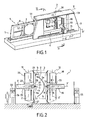
- a machining device as illustrated in FIG. Fig. 1 and designated as a whole by the reference 1, allows the machining of a panel 2 may have a general shape complex, non-developable, such as, for example, convex or concave or, again, locally convex and locally concave.
- the device 1 comprises a frame 3 which, according to the illustrated example, is made in the form of a kind of substantially vertical gantry, defining a window 4 inside which the panel to be machined to be placed, being maintained by support means 5.
- the support means 5 are made in the form of a removable frame capable of being immobilized, at the level of the window 4, on the frame 3 via locking means 6 can be made in any suitable manner.
- the machining device 1 further comprises means 10 for moving at least one tool and, according to the illustrated example, exactly one machining tool 11, as well as displacement means 12 of at least one and, according to the illustrated example, exactly one holding element 13.
- the displacement means 10 and 11 are, as shown more particularly by the Fig. 2 , adapted on both sides of the frame 3, so that the panel 2 is interposed between the machining tool 11 and the holding element 13.
- the displacement means 10 of the tool comprise a beam 20, mobile in translation along at least one and, according to the example, two guideways 21 of X axis supported by the frame 3.
- the X axis of the guide tracks 21 then has a substantially horizontal orientation.
- the beam 20 is associated with motor means, not shown, and controlled by a control unit 22, the different functionalities will be specified later, it being understood that the control unit 22 is adapted to allow automated operation of the machining device 1.
- the displacement means 10 of the tool 11 further comprise a carriage 23 which can be moved in translation along a Z- axis guideway 24 carried by the beam 20.
- Z axis has a substantially vertical orientation and is perpendicular to the X axis , so that the X and Z axes define a plane also vertical.
- the carriage 23 is also associated with motor means, not shown, ensuring its movement along the track 24 and being controlled by the control unit 22.
- the displacement means 10 also comprise an arm 25, telescopic in Y- axis translation which is carried by the carriage 23.
- the translation axis Y is substantially perpendicular to the plane defined by the X axes. and Z cross translations of the carriage 23.
- the telescopic arm is further associated with motor means, not shown, controlled by the control unit 22.
- the telescopic arm 25 is equipped, at its end facing the frame 3, a head support 26, rotatable relative to the arm 25 along an axis of rotation R 1 parallel to the Y axis and, in the example, coincides with this axis Y.
- the head support 26 is associated with motor means not shown and driven by the control unit 22.
- the displacement means 10 comprise a tool head 27, adapted to the head support 26, so as to be rotatable relative to the support 26 along an axis of rotation R 2 , substantially perpendicular to the axis R 1.
- the rotational movement of the head 27 around the axis R 2 is associated with motor means, not shown, controlled by the control unit 22.
- the configuration thus gives the tool 11, integral with the tool holder head 27, five degrees of freedom, namely three degrees of freedom in translation of X, Y, Z axes and two degrees of freedom. in rotation of axes R 1 and R 2 .
- the tool head 27 is equipped with motor means, not shown, for driving the tool 11 in machining rotation along an axis ⁇ which, according to the example illustrated in FIG. Fig. 2 , is substantially coincident with the Y axis , insofar as this figure corresponds to a rest or waiting position.
- the axis ⁇ can have different orientations while remaining substantially perpendicular to the axis R 2 .
- the drive means for rotating the tool 11, fitted to the head 27, are also controlled by the control unit 22.
- the machining tool 11 can be made in different ways and, according to the illustrated example, as is more particularly apparent from the Fig. 3 , the tool 11 is produced in the form of a milling cutter, driven in rotation of axis ⁇ , by the motor means, equipping the tool holder head 27.
- the holding element 13 can be made in any suitable manner and, according to the illustrated example, the holding element 13 has, at an end 40 opposite to the support head 37, a sphere 41 intended for define a substantially punctual support on the panel 2, as will appear later.
- the sphere 41 is made of an elastically deformable material, such as, for example, a polymeric synthetic material or a plastics material. The elastic deformation capacity of the sphere is then used to dampen the machining vibrations.
- the sphere could also be made of other materials, such as, for example, a metal such as steel or other suitable metal alloys.
- the sphere 41 is located substantially at the end of a frustoconical body 42 of axis ⁇ ', substantially perpendicular to the axis R' 2 of rotation of the support head 37. sphere 41 is then adapted in the body 42 so as to be able to roll on the panel 2, as will be apparent from the following.
- the holding member 13 is removably fitted on the support head 37, so that it can be changed quickly or replaced by a tool.
- the head 37 is, like the support head 27, equipped with means for rotating a tool about the axis ⁇ ', these drive means being driven by the means of order 22.
- the machining device thus constituted is then implemented as follows. Firstly, a panel 2 is placed at the level of the window 4.
- the frame 3 has a side window 50 through which the support means, constituted by the mobile frame 5 are engaged to come to place the plate 2 between the tool 11 and the holding member 13, as shown in Fig. 2 .
- the frame 5 is then locked on the frame 3, so that the panel 2 is perfectly immobile with respect to the frame 3.
- the control unit 22 controls the operation of the means 10 for moving the tool 11 and the displacement means 12 of the holding element 13, in order to place the tool 11 in operation in contact with a face 2 T , referred to as machining, of the panel 2 at a so-called working zone 50 , as illustrated in FIG. Fig. 3 .
- the control unit 22 controls the operation of the displacement means 12, so as to place the holding element 13 and, more particularly, the sphere 41, bearing on a face 2 M , so-called maintaining the panel 2, at a holding zone 52, located on the holding face 2 M opposite the machining face 2 T , the holding zone 52 being situated opposite, relative to the panel 2, of the working zone 50.
- the unit 22 controls a coordinated movement of the machining tool 11 in operation and the holding element 13 bears on the panel 2, so as to machine, in part at least, the machining face 2 T of panel 2.
- the control unit ensures the coordinated movement of the tool 11 and the holding element 13, so as to preserve, during this joint movement, the opposition of the zones support 52 and work 50.
- the sphere 41 then rolls on the holding face 2M of the panel 2. that is to say that the movement of the tool 11 and the element Maintaining 13, with respect to the panel, has a decomposition, according to the tangent plane and the plane normal to the surface of the panel at the machining area, whose at least tangential component is non-zero.
- the coordinated movement therefore has at least one component tangent to the surface of the panel and, in certain phases of the machining at least, also a component normal to the surface of the panel, as is the case for the tools when the adjustment of the pass depth in particular.
- the unit 22 controls these displacements so as to maintain, throughout the machining phase of the panel 2, on the one hand, the perpendicularity of the support axis ⁇ 'of the holding element 13 with the surface of the support zone 52 and, on the other hand, the conjugation of the axis ⁇ 'and of the axis A of rotation of the tool 11, so that during the entire phase of machining and coordinated displacement, the axes ⁇ and ⁇ 'are merged.
- the combination of the holding elements and the machining tool 11 it is possible, by the combination of the holding elements and the machining tool 11, to ensure a high precision machining of the panel 2, without deformation of this panel.
- telemetry means 55 for example laser telemetry means for performing a particularly accurate mapping of the 2 M holding face of the panel 2 before machining it.
- This telemetry thus makes it possible to obtain a perfect frame of reference which will make it possible to know very precisely the thickness of the panel 2 in all points of the latter after machining. Indeed, the residual thickness will then be determined by the distance between the end of the tool 11 and the holding member 13 and, more particularly, the sphere 41 during machining, this distance then corresponding to the residual thickness of the panel 2 after machining.
- telemetry means 56 for accurately measuring the coordinates of the working face 2 T of the panel.
- the combined implementation of the telemetry means 55 and 56 makes it possible to have a perfect knowledge of the geometry of the panel 2 before and after machining.
- the frame 5 is unlocked to be removed and allow the implementation of another frame.
- the invention thus constituted allows a work in masked time and it is possible, by the implementation of different frames, to provide a machining of different types of panels 2.
- the frame 5 is provided with a cross member 57, movable in translation and to adjust the useful dimensions of the frame 5, so as to allow support with a single type panel frame with different dimensions.
- the counter-support element 58 comprises three isostatic telescopic fingers 59 in permanent contact with the working face 2T of the panel 2.
- the fingers 59 are preferably arranged in a triangle, although any other configuration may to be considered.
- the fingers 59 constituting the counter-support element, make it possible to avoid any phenomenon of swallowing the panel by the tool 11 and can also provide damping of machining vibrations.
- displacement means in translation of the tool in the direction ⁇ perpendicular to the axis of rotation R 2 it is also implemented, at the level of the holder-holding head 37, means for translational movement of the holding element in the direction ⁇ 'perpendicular to the axis of rotation R' 2 .
- these translation displacement means are associated with motor means controlled by the control unit.
- Such a configuration is particularly suitable for machining the hull, so as to make it perfectly conform to the theoretical model sought.
- control unit will control the installation on the basis of the theoretical three-dimensional definition file of the shell to be produced and will then control the operation of the various components of the machining device for this purpose.
- the machining device according to the invention can also be controlled in the context of a machining mode, which could be qualified as a correction, insofar as, after a telemetry phase making it possible to detect the actual shape of the shell, the control unit will control the operation of the device to achieve the desired shape from the actual form.
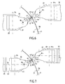
- Such three-dimensional machining of a shell is particularly favored by the kinematics of the ends of the arms 25 and 26 and the tool supports 26 and holding element, as illustrated in FIG. Fig. 3 .
- control unit has difficulty calculating the rotations along the axes R 1 , R 2 and R ' 1 , R' 2 to reach the machining and bearing areas.
- the invention proposes, in one embodiment, such as more particularly illustrated in FIG. Fig. 6 , to suppress the rotational movements about the axes R 1 and R ' 1 of the head supports 26 and 36.
- the rotational movements along R 1 and R' 1 are replaced by a rotation of the head supports 26, 36 around axes, respectively R 3 and R ' 3 , substantially vertical or contained in a vertical plane.
- the axes of rotation R 2 and R ' 2 are placed so as to be perpendicular, respectively, to the axes R 3 and R' 3 .
- the machining device comprises the motor means controlled by the control unit and associated in rotation about the axes R 3 and R ' 3 .
- the Fig. 7 illustrates an alternative embodiment of the machining device, as illustrated in FIG. Fig. 6 .
- the rotational movements along the axes R 1 and R ' 1 are combined with the rotational movements along the axes R 2 , R 3 and R' 2 , R ' 3 .
- the end of the arm 25 comprises a cradle 60, rotatable about the horizontal axis R 1 parallel to the axis Y.
- the head support 26 is then adapted to the cradle 60 while being movable relative to the latter rotating about the axis R 3 perpendicular to the axis R 1 , while the tool head 27 is rotatable relative to the support 26 along the axis R 2 perpendicular to both the axis R 1 and the axis R 3 .
- the assembly comprising the end of the arm 35 on which is adapted the cradle 60, the head support 26, and the tool head 27 forms what could be called a head crew.
- the end of the arm 35 comprises a cradle 61, rotatable about the horizontal axis R ' 1 .
- the head support 36 is fitted on the cradle 61 while being mobile with respect to said cradle in rotation about the axis R ' 3 perpendicular to the axis R' 1 .
- the holding element holding head 37 is rotatable relative to the support 37 along the axis R ' 2 perpendicular to the axes of rotation R' 1 and R ' 3 .
- the control unit 22 controls the machining device giving a priority to the movement combinations according to R 2 , R 3 and, respectively, R ' 2 , R' 3 with respect to the rotations according to R 1 , respectively R ' 1 .
Landscapes
- Engineering & Computer Science (AREA)
- Mechanical Engineering (AREA)
- Manufacturing & Machinery (AREA)
- Transportation (AREA)
- Aviation & Aerospace Engineering (AREA)
- Machine Tool Units (AREA)
- Electrical Discharge Machining, Electrochemical Machining, And Combined Machining (AREA)
- Jigs For Machine Tools (AREA)
- Auxiliary Devices For Machine Tools (AREA)
Claims (30)
- Verfahren zur Bearbeitung einer Platte (2), umfassend:- ein Anordnen wenigstens eines Bearbeitungswerkzeugs (11) im Bereich einer Arbeitszone (50) einer sogenannten Bearbeitungsfläche (2T) der Platte (2),- ein Anordnen wenigstens eines Halteelements (13) im Bereich einer Stützzone (52), die sich einerseits auf einer sogenannten Haltefläche (2M) der Platte (2) gegenüber der Bearbeitungsfläche (2T) und andererseits in Bezug zur Platte (2) gegenüber der Arbeitszone (50) befindet, wobei das Halteelement (13) dazu vorgesehen ist, auf die Stützzone (52) einzuwirken, und gekennzeichnet durch- ein koordiniertes Verschieben im Bereich der Platte und gemäß einer Bewegung, die wenigstens eine die Oberfläche der Platte tangierende Komponente aufweist, des Bearbeitungswerkzeugs (11) während des Betriebs und des Halteelements (13), das auf die Stützzone (52) einwirkt, um während der Verschiebung die Gegenüberstellung der Stütz- (52) und Arbeitszonen (50) beizubehalten, um wenigstens einen Teil der Bearbeitungsfläche zu bearbeiten.
- Bearbeitungsverfahren nach Anspruch 1, dadurch gekennzeichnet, daß das Halteelement (13) dazu vorgesehen ist, auf die Stützzone einzuwirken, wobei es während der koordinierten Verschiebung in Kontakt mit der Platte (2) angeordnet ist.
- Bearbeitungsverfahren nach Anspruch 1 oder 2, dadurch gekennzeichnet, daß das Halteelement (13) auf die Platte eine Stützkraft mit der Richtung Δ' senkrecht auf die Oberfläche der Stützzone (52) ausübt.
- Bearbeitungsverfahren nach einem der Ansprüche 1 bis 3, dadurch gekennzeichnet, daß es ein Anlegen von wenigstens einem Gegenstützelement (58) im Bereich der Arbeitszone (50) einsetzt.
- Bearbeitungsverfahren nach einem der Ansprüche 1 bis 4, dadurch gekennzeichnet, daß das Bearbeitungswerkzeug (11) dazu vorgesehen ist, eine Bearbeitung durch Materialabbruch oder -abhebung durchzuführen, und eine Drehbewegung um sich selbst um die Achse Δ ausführt.
- Bearbeitungsverfahren nach Anspruch 5, dadurch gekennzeichnet, daß das Halteelement (13) auf die Stützzone eine Kraft mit der Richtung Δ' ausübt, und daß während der Bearbeitung während der koordinierten Verschiebung des Bearbeitungswerkzeugs (11) und des Halteelements (13) die Achsen Δ und Δ' im wesentlichen zusammenfallen.
- Bearbeitungsverfahren nach einem der Ansprüche 1 bis 6, dadurch gekennzeichnet, daß es eine Dämpfung der Bearbeitungsschwingungen wenigstens im Bereich des Halteelements (13) einsetzt.
- Bearbeitungsverfahren nach einem der Ansprüche 1 bis7, dadurch gekennzeichnet, daß das Halteelement (13) und das Bearbeitungswerkzeug (11) jeweils mit wenigstens fünf Freiheitsgraden verschoben werden.
- Bearbeitungsverfahren nach Anspruch 8, dadurch gekennzeichnet, daß das Halteelement (13) und das Bearbeitungswerkzeug (11) jeweils mit drei Freiheitsgraden zur Translationsverschiebung mit den Achsen X, Y, Z bzw. X', Y', Z' und zwei Verschiebegraden in Drehung mit den Achsen R1, R2 bzw. R'1, R'2 verschoben werden, wobei R1' R'1 parallel zu den Achsen Y, Y' bzw. R2, R'2 parallel zu den Ebenen X, Z bzw. X', Z' sind.
- Bearbeitungsverfahren nach einem der Ansprüche 1 bis 9, dadurch gekennzeichnet, daß die zu bearbeitende Platte (2) mit einer im wesentlichen vertikalen Ausrichtung angeordnet ist.
- Bearbeitungsverfahren nach einem der Ansprüche 1 bis 9, dadurch gekennzeichnet, daß die Platte (2) im wesentlichen während ihrer Bearbeitung unbeweglich ist.
- Bearbeitungsverfahren nach einem der Ansprüche 1 bis 11, dadurch gekennzeichnet, daß es eine Bestimmung der tatsächlichen Geometrie der Haltefläche (2M) vor der Bearbeitung sowie eine Bearbeitung der Platte (2) mit einer vorbestimmten Bearbeitungsdicke einsetzt, wobei während der koordinierten Verschiebung zur Bearbeitung das Halteelement (13) und das Bearbeitungselement (11) in einem Abstand angeordnet werden, der der vorbestimmten Dicke entspricht.
- Bearbeitungsverfahren nach einem der Ansprüche 1 bis 12, dadurch gekennzeichnet, daß das Halteelement den Halt der Haltefläche (2M) der Platte ohne Bearbeitung dieser Haltefläche (2M) sichert.
- Vorrichtung zur Bearbeitung wenigstens einer Platte (2), umfassend:- Mittel (5) zum Stützen der Platte (2), die dazu ausgeführt sind, einen gleichzeitigen Zugriff auf zwei gegenüber liegende Seiten der Platte, Bearbeitungsfläche (2T) und Haltefläche (2M) genannt, zu gestatten,- Mittel (10) zum Verschieben wenigstens eines Bearbeitungswerkzeugs (11),- Mittel (12) zum Verschieben wenigstens eines Halteelements (13),- eine Einheit (22) zur Steuerung der Verschiebemittel (10, 12) des Bearbeitungswerkzeugs (11) und des Halteelements (13), wobei die Einheit (22) dazu vorgesehen ist, während eines Schrittes der Bearbeitung der Platte (2):dadurch gekennzeichnet, daß sie ferner ein Halteelement (13) umfaßt, das dazu ausgeführt ist, auf die Haltefläche während des Verschiebens einzuwirken, und daß die Einheit (22) dazu vorgesehen ist, eine koordinierte Verschiebung im Bereich der Platte und in einer Bewegung, die wenigstens eine die Oberfläche der Platte (2) tangierende Komponente aufweist, des Bearbeitungswerkzeugs (11) während der Funktion und des Halteelements (13), das auf die Stützzone einwirkt, zu gewährleisten, um während der Verschiebung die Gegenüberstellung der Stütz- (52) und Arbeitszone (50) beizubehalten, um wenigstens einen Teil der Bearbeitungsfläche (2T) der Platte (2) zu bearbeiten.-- das Bearbeitungswerkzeug (11) im Bereich einer Arbeitszone (50) der Bearbeitungsfläche (2T) der Platte (2) anzuordnen,-- das Halteelement (13) im Bereich einer Stützzone (52) anzuordnen, die sich auf der Haltefläche (2M) und gegenüber der Arbeitszone (50) befindet,
- Vorrichtung nach Anspruch 14, dadurch gekennzeichnet, daß das Halteelement (13) dazu vorgesehen ist, in Kontakt mit der Platte (2) während der koordinierten Verschiebung angeordnet zu werden.
- Vorrichtung nach Anspruch 14 oder 15, dadurch gekennzeichnet, daß die Verschiebemittel (10, 12) des Werkzeugs (11) und des Halteelements (13) jeweils wenigstens fünf Verschiebeachsen aufweisen, um dem Werkzeug (11) und dem Halteelement (13) wenigstens fünf Freiheitsgrade zu verleihen.
- Vorrichtung nach Anspruch 16, dadurch gekennzeichnet, daß die Verschiebemittel (10, 12) des Werkzeugs (11) und des Halteelements (13) jeweils drei Verschiebegrade in Translation mit der Achse X, Y, Z bzw. X', Y', Z' und zwei Verschiebegrade in Drehung mit den Achsen R1, R2 bzw. R'1, R'2, wobei R1 und R'2 zur Achse Y bzw. Y' parallel sind und R2, R'2 zu den Ebenen parallel sind, die von den Achsen X, Z bzw. X', Z' definiert sind.
- Vorrichtung nach Anspruch 16 oder 17, dadurch gekennzeichnet, daß:- die Mittel (10) zum Verschieben des Werkzeugs (11) umfassen:-- einen in Translation entlang wenigstens eines Führungsweges (21) beweglichen Träger (20) mit der Achse X, der von einem Gestell (3) getragen wird und mit von der Steuereinheit (22) gesteuerten Antriebsmitteln verbunden ist,-- einen in Translation entlang eines Führungsweges (24) beweglichen Wagen (23) mit der Achse Z, der vom Träger (20) getragen wird und mit von der Steuereinheit (22) gesteuerten Antriebsmitteln verbunden ist, wobei die Achse Z im wesentlichen senkrecht auf die Achse X ist,-- einen in Translation teleskopisch verschiebbaren Arm (25) mit der Achse Y, der vom Wagen (23) getragen wird und mit von der Steuereinheit (22) gesteuerten Antriebsmitteln verbunden ist, wobei die Achse Y im wesentlichen senkrecht auf die durch die Achsen X, Z definierte Ebene ist,-- einen Kopfträger (26), der an einem Ende des Teleskoparms (25) ausgebildet und in Drehung in Bezug zum Arm entlang einer Achse R1 parallel zur Achse Y beweglich ist und mit von der Steuereinheit (22) gesteuerten Antriebsmitteln verbunden ist,-- einen Werkzeugtragkopf (27), der am Kopfträger (26) vorgesehen und in Drehung in Bezug zum Träger (26) entlang einer Achse R2 senkrecht auf die Achse Y beweglich ist und mit von der Steuereinheit (22) gesteuerten Antriebsmitteln verbunden ist,- wobei die Verschiebemittel (12) des Halteelements (13) umfassen:-- einen in Translation entlang wenigstens eines Führungsweges beweglichen Träger (30) mit der Achse X', der von dem Gestell (3) getragen wird und mit von der Steuereinheit (22) gesteuerten Antriebsmitteln verbunden ist,-- einen in Translation entlang eines Führungsweges (31) beweglichen Wagen (33) mit der Achse Z', der vom Träger (30) getragen wird und mit von der Steuereinheit (22) gesteuerten Antriebsmitteln verbunden ist, wobei die Achse Z' im wesentlichen senkrecht auf die Achse X' ist,-- einen in Translation teleskopisch verschiebbaren Arm (35) mit der Achse Y', der vom Wagen (33) getragen wird und mit von der Steuereinheit (22) gesteuerten Antriebsmitteln verbunden ist, wobei die Achse Y' im wesentlichen senkrecht auf die durch die Achsen X', Z' definierte Ebene ist,-- einen Kopfträger (36), der an einem Ende des Teleskoparms (35) ausgebildet und in Drehung in Bezug zum Arm (35) entlang einer Achse R'1 parallel zur Achse Y' beweglich ist und mit von der Steuereinheit (22) gesteuerten Antriebsmitteln verbunden ist,-- einen Werkzeugtragkopf (37), der am Kopfträger (36) vorgesehen und in Drehung in Bezug zum Träger entlang einer Achse R'2 senkrecht auf die Achse Y' beweglich ist und mit von der Steuereinheit (22) gesteuerten Antriebsmitteln verbunden ist,- und daß die Stützmittel (5) am Gestell vorgesehen sind, um zwischen den Verschiebemitteln (10) des Werkzeugs (11) und den Mitteln (1) zum Verschieben (12) des Halteelements (13) angeordnet zu werden.
- Vorrichtung nach Anspruch 18, dadurch gekennzeichnet, daß:- die Stütze (26) des Werkzeugtragekopfes (27) einerseits an einen Schlitten (60) angepaßt ist, mit dem das Ende des Teleskoparms (25) ausgestattet ist, und der in Drehung um die Achse R1 beweglich ist, und andererseits in Bezug zum Schlitten (60) in Drehung um eine Achse R3 senkrecht auf die Achse R1 beweglich ist,- die Stütze (36) des Werkzeugtragekopfes (37) einerseits an einen Schlitten (61) angepaßt ist, mit dem das Ende des Teleskoparms (35) ausgestattet ist, und der in Drehung um die Achse R'1 beweglich ist, und andererseits in Bezug zum Schlitten (61) in Drehung um eine Achse R'3 senkrecht auf die Achse R'1 beweglich ist.
- Vorrichtung nach einem der Ansprüche 17 bis 19, dadurch gekennzeichnet, daß die Achsen X, Z und X', Z' im wesentlichen parallele Vertikalebenen definieren.
- Vorrichtung nach einem der Ansprüche 18 bis 20, dadurch gekennzeichnet, daß der Werkzeugtragekopf (27) Mittel zum Drehantrieb des Werkzeugs entlang einer im wesentlichen senkrecht auf die Achse R2 verlaufenden Achse Δ umfaßt.
- Vorrichtung nach einem der Ansprüche 17 bis 21, dadurch gekennzeichnet, daß sie umfaßt:- Mittel zur Translationsverschiebung des Werkzeugs (11) in eine Richtung Δ senkrecht auf die Drehachse (R2),- und Mittel zur Translationsverschiebung des Halteelements (13) entlang einer Richtung Δ' senkrecht auf die Drehachse (R'2).
- Vorrichtung nach einem der Ansprüche 14 bis 22, dadurch gekennzeichnet, daß die Verschiebemittel (10) des Werkzeugs (11) wenigstens ein Gegenstützelement (55) auf der Bearbeitungsfläche (2T) der Platte (2T) umfassen.
- Vorrichtung nach einem der Ansprüche 14 bis 23, dadurch gekennzeichnet, daß sie Mittel (41) zur Dämpfung der Bearbeitungsschwingungen umfaßt.
- Vorrichtung nach Anspruch 24, dadurch gekennzeichnet, daß die Dämpfungsmittel (41) an die Verschiebemittel (12) des Halteelements (13) angepaßt sind.
- Vorrichtung nach einem der Ansprüche 14 bis 25, dadurch gekennzeichnet, daß das Halteelement (13) wenigstens eine Stützkugel (41) umfaßt, die dazu bestimmt ist, auf der Haltefläche (2M) der Platte (2) während der Bearbeitung zu rollen.
- Vorrichtung nach Anspruch 25, dadurch gekennzeichnet, daß die Stützkugel (41) aus einem elastisch verformbaren Material hergestellt ist, um die Bearbeitungsschwingungen zu dämpfen.
- Vorrichtung nach einem der Ansprüche 14 bis 27, dadurch gekennzeichnet, daß die Stützmittel (5) der Platte (2) abnehmbar sind, und daß sie Mittel (6) zur Festlegung der Stützmittel (5) während der Bearbeitung der Platte umfaßt.
- Vorrichtung nach Anspruch 28, dadurch gekennzeichnet, daß die Stützmittel einen abnehmbaren Rahmen (5) umfassen, der mit Mitteln zur Befestigung einer zu bearbeitenden Platte versehen ist.
- Vorrichtung nach Anspruch 29, dadurch gekennzeichnet, daß der Rahmen wenigstens eine bewegliche Querstrebe umfaßt, die eine Anpassung der Abmessungen des Rahmens ermöglicht.
Priority Applications (2)
| Application Number | Priority Date | Filing Date | Title |
|---|---|---|---|
| PL04805273T PL1689558T3 (pl) | 2003-10-24 | 2004-10-22 | Sposób i urządzenie do obróbki płyt |
| SI200430909T SI1689558T1 (sl) | 2003-10-24 | 2004-10-22 | Postopek in priprava za obdelavo plošč |
Applications Claiming Priority (3)
| Application Number | Priority Date | Filing Date | Title |
|---|---|---|---|
| FR0312484A FR2861325B1 (fr) | 2003-10-24 | 2003-10-24 | Procede et dispositif d'usinage de panneaux |
| FR0314109A FR2861326B3 (fr) | 2003-10-24 | 2003-12-02 | Procede et dispositif d'usinage de panneaux |
| PCT/FR2004/002709 WO2005046931A1 (fr) | 2003-10-24 | 2004-10-22 | Procede et dispoitif d’usinage de panneaux |
Publications (2)
| Publication Number | Publication Date |
|---|---|
| EP1689558A1 EP1689558A1 (de) | 2006-08-16 |
| EP1689558B1 true EP1689558B1 (de) | 2008-08-06 |
Family
ID=34424862
Family Applications (1)
| Application Number | Title | Priority Date | Filing Date |
|---|---|---|---|
| EP04805273A Expired - Lifetime EP1689558B1 (de) | 2003-10-24 | 2004-10-22 | Verfahren und vorrichtung zur bearbeitung von platten |
Country Status (13)
| Country | Link |
|---|---|
| US (1) | US7682112B2 (de) |
| EP (1) | EP1689558B1 (de) |
| JP (1) | JP4742045B2 (de) |
| AT (1) | ATE403517T1 (de) |
| BR (1) | BRPI0415768B1 (de) |
| CA (1) | CA2543146C (de) |
| DE (1) | DE602004015636D1 (de) |
| ES (1) | ES2313115T3 (de) |
| FR (1) | FR2861326B3 (de) |
| PL (1) | PL1689558T3 (de) |
| RU (1) | RU2358850C2 (de) |
| SI (1) | SI1689558T1 (de) |
| WO (1) | WO2005046931A1 (de) |
Families Citing this family (52)
| Publication number | Priority date | Publication date | Assignee | Title |
|---|---|---|---|---|
| FR2865952B1 (fr) | 2004-02-10 | 2006-06-23 | Airbus France | Procede et dispositif d'usinage mecanique de panneaux flexibles en particulier de forme complexe |
| DE102004051915B4 (de) * | 2004-10-26 | 2012-11-22 | Airbus Operations Gmbh | Vorrichtung zur Bearbeitung von Bauteilen für Verkehrsmittel |
| US8549723B2 (en) * | 2007-05-11 | 2013-10-08 | The Boeing Company | Method and apparatus for squeezing parts such as fasteners |
| US8301302B2 (en) * | 2008-05-08 | 2012-10-30 | The Boeing Company | Synchronous robotic operation on a structure having a confined space |
| US20100217437A1 (en) * | 2009-02-24 | 2010-08-26 | Branko Sarh | Autonomous robotic assembly system |
| US8776357B2 (en) * | 2009-05-04 | 2014-07-15 | Mori Seiki Co. Ltd | System and method of synchronized machining |
| US8666546B2 (en) * | 2009-07-10 | 2014-03-04 | The Boeing Company | Autonomous robotic platform |
| DE102009050476B4 (de) * | 2009-10-23 | 2015-06-18 | Airbus S.A.S. | Bohrvorrichtung |
| DE102010002268B4 (de) * | 2010-02-24 | 2013-10-17 | Prof. Dr.-Ing., Siegfried Schmalzried | Bearbeitungsstation zur Bearbeitung von Rotorblättern für Windkraftanlagen |
| EP2548667B1 (de) | 2010-03-18 | 2019-01-16 | Mitsubishi Heavy Industries, Ltd. | Formverfahren für ein plattenförmiges werkstück und formartikel |
| DE102010022582A1 (de) * | 2010-06-03 | 2011-12-08 | Brötje-Automation GmbH | Verfahren zur Steuerung einer getakteten Fertigungsstraße |
| IT1402474B1 (it) | 2010-11-05 | 2013-09-13 | Cms Spa | Impianto per lavorazioni di alleggerimento di pannelli o lastre sottili mediante asportazione di materiale |
| EP2492046B1 (de) * | 2011-02-22 | 2013-06-26 | MTU Aero Engines GmbH | Verfahren zur Bearbeitung eines Bauteils |
| EP2689889B1 (de) * | 2011-03-24 | 2015-07-22 | Murata Machinery, Ltd. | Maschinenwerkzeugsystem |
| JP5916293B2 (ja) | 2011-03-31 | 2016-05-11 | 三菱重工業株式会社 | 板状ワークの成形方法 |
| ITTO20110420A1 (it) * | 2011-05-12 | 2012-11-13 | Fidia Spa | Testa porta-utensile per macchine utensili |
| KR101320027B1 (ko) * | 2011-10-06 | 2013-10-21 | 주식회사 포스코 | 연마 장치 및 연마 방법 |
| JP5854811B2 (ja) * | 2011-12-19 | 2016-02-09 | Dmg森精機株式会社 | 工作機械 |
| US9533371B2 (en) * | 2012-01-17 | 2017-01-03 | United Technologies Corporation | Apparatus and method for on line surface enhancement of a workpiece |
| RU2615754C2 (ru) * | 2012-03-29 | 2017-04-11 | Прокопенко Дмитрий Олегович | Способ обработки соединительных торцов отделочной панели |
| ES2388972B1 (es) * | 2012-04-24 | 2013-06-17 | Manuel Torres Martínez | Util de sujeción dinámica de piezas para mecanizado |
| DE102013006506A1 (de) * | 2013-04-16 | 2014-10-16 | Brötje-Automation GmbH | Bearbeitungsanlage für Flugzeugstrukturbauteile |
| CN104227473A (zh) * | 2013-06-17 | 2014-12-24 | 哈尔滨飞机工业集团有限责任公司 | 一种零部件机械加工过程中的支撑装置 |
| JP6572132B2 (ja) * | 2013-12-26 | 2019-09-04 | 川崎重工業株式会社 | 低剛性ワーク機械加工支援システム |
| US10189214B2 (en) | 2014-03-28 | 2019-01-29 | Composite Cluster Singapore Pte. Ltd. | Freespace composite manufacturing process and device |
| RU2589957C2 (ru) * | 2014-06-09 | 2016-07-10 | федеральное государственное бюджетное образовательное учреждение высшего образования "Ижевский государственный технический университет имени М.Т. Калашникова" | Способ изготовления нежесткой детали |
| DE102014108629A1 (de) | 2014-06-18 | 2015-12-24 | Brötje-Automation GmbH | Fertigungssystem |
| DE102014113663A1 (de) * | 2014-09-22 | 2016-03-24 | Broetje-Automation Gmbh | Bearbeitungsanlage für Flugzeugstrukturbauteile |
| US20160138299A1 (en) * | 2014-10-20 | 2016-05-19 | John Powers, III | Multiple driver head post driving system |
| DE202015104273U1 (de) | 2015-08-13 | 2016-11-15 | Brötje-Automation GmbH | Bearbeitungsstation |
| US9937625B2 (en) * | 2015-12-29 | 2018-04-10 | The Boeing Company | Self-locating robots |
| ES2632166B1 (es) | 2016-02-08 | 2018-05-08 | Manuel Torres Martinez | Dispositivo de mecanizado de superficies laminares curvas |
| DE102016210089B4 (de) * | 2016-06-08 | 2025-02-20 | Airbus Operations Gmbh | Verfahren zum Fügen von Hautabschnitten eines umfänglich geschlossenen Rumpfes |
| US10265760B2 (en) * | 2016-08-12 | 2019-04-23 | The Boeing Company | Sliding adjustable toggle clamp |
| CN106334960B (zh) * | 2016-10-14 | 2018-08-28 | 天津大学 | 用于镜像铣的气动式变刚度的柔性随动顶推头 |
| CN106392719B (zh) * | 2016-10-14 | 2018-08-28 | 天津大学 | 实时测厚的气动式变刚度的柔性镜像铣削支撑头 |
| US10596691B2 (en) * | 2017-01-30 | 2020-03-24 | Stuart Topp | Devices and methods of using them to assemble two or more workpieces to each other |
| DE102017116718A1 (de) | 2017-07-24 | 2019-01-24 | Broetje-Automation Gmbh | Bearbeitungsanlage für Flugzeugstrukturbauteile |
| JP7118745B2 (ja) | 2018-05-30 | 2022-08-16 | 三菱重工業株式会社 | 加工装置及び加工方法 |
| US11110606B2 (en) * | 2019-01-02 | 2021-09-07 | The Boeing Company | Coordinating work within a multi-robot cell |
| CN109848724B (zh) * | 2019-02-19 | 2020-11-03 | 大连理工大学 | 一种用于薄壁件加工的动压支撑装置及方法 |
| CN109848744B (zh) * | 2019-02-19 | 2020-09-11 | 大连理工大学 | 一种针对于薄壁件的磁力支撑装置及方法 |
| CN110039095A (zh) * | 2019-04-08 | 2019-07-23 | 科德数控股份有限公司 | 一种卧式五轴翻板加工中心 |
| CN110560758B (zh) * | 2019-08-26 | 2021-02-19 | 上海拓璞数控科技股份有限公司 | 双五轴镜像同步加工系统及镜像同步补偿铣削方法 |
| EP4177166B1 (de) | 2021-11-03 | 2025-04-02 | The Boeing Company | System und verfahren zur dämpfung von maschineninduzierten schwingungen in einem werkstück |
| NL2029836B1 (en) * | 2021-11-19 | 2023-06-13 | Boeing Co | System and method for damping machine-induced vibrations in a workpiece |
| JP2023070091A (ja) | 2021-11-03 | 2023-05-18 | ザ・ボーイング・カンパニー | ワークにおける機械励起振動を減衰させるためのシステム及び方法 |
| US11858661B2 (en) * | 2022-02-10 | 2024-01-02 | The Boeing Company | Method of manufacturing an assembly having a nominal thickness skin panel |
| CN115415801B (zh) * | 2022-10-17 | 2023-10-24 | 烟台大学 | 弱刚性环形轮转曲面薄壁工件的机器人支撑装置和加工方法 |
| DE102023130101B3 (de) | 2023-10-31 | 2025-03-20 | "Les Graveurs" Münz- und Medaillengestaltung und Gravuren GmbH | Kennzeichnungsverfahren und Kennzeichnungsanlage |
| CN117420761B (zh) * | 2023-12-19 | 2024-02-13 | 合肥工业大学 | 镜像铣削中随动支撑头的点位布局优化方法及随动支撑头 |
| CN118268634B (zh) * | 2024-06-03 | 2024-08-23 | 安徽明途交通科技有限公司 | 一种中间球面板成型装置及其成型方法 |
Family Cites Families (20)
| Publication number | Priority date | Publication date | Assignee | Title |
|---|---|---|---|---|
| SU950474A1 (ru) * | 1980-11-27 | 1982-08-15 | Предприятие П/Я М-5671 | Установка дл клепки |
| US5248074A (en) * | 1987-12-02 | 1993-09-28 | Gemcor Engineering Corp. | Five axis riveter and system |
| US4967947A (en) * | 1988-03-23 | 1990-11-06 | Branko Sarh | Multi-function riveting/fastening machine and method of operating |
| US4885836A (en) * | 1988-04-19 | 1989-12-12 | Imta | Riveting process and apparatus |
| JPH0758184B2 (ja) * | 1988-11-29 | 1995-06-21 | 日産自動車株式会社 | 三次元測定装置 |
| US4955119A (en) * | 1989-07-11 | 1990-09-11 | Imta | Multi-task end effector for robotic machining center |
| US4995148A (en) * | 1990-03-30 | 1991-02-26 | Imta | Robotically controlled multi-task end effector |
| US5259104A (en) * | 1990-12-21 | 1993-11-09 | The Boeing Company | Rivet recovery method |
| DE69107196T2 (de) * | 1991-04-05 | 1995-05-24 | Torres Martinez M | Werkzeugmaschineneinrichtung zum Einspannen und Bearbeiten. |
| US5341556A (en) * | 1991-06-28 | 1994-08-30 | The United States Of America As Represented By The Secretary Of The Air Force | Method and apparatus for manufacture of reinforced panels |
| US5611130A (en) * | 1993-06-28 | 1997-03-18 | Gemcor Engineering Corp. | Multi-position rotary head apparatus |
| US5404641A (en) * | 1993-08-16 | 1995-04-11 | Avco Corporation | Method of drilling through contiguous plate members using a robotic drill clamp |
| US5555616A (en) * | 1993-10-13 | 1996-09-17 | Gemcor Engineering Corporation | Method and apparatus for positioning of tooling efficiently |
| US5615474A (en) * | 1994-09-09 | 1997-04-01 | Gemcor Engineering Corp. | Automatic fastening machine with statistical process control |
| US5584621A (en) | 1995-06-13 | 1996-12-17 | Bertsche Engineering Corp. | Direct drive multiple axes rotary spindle head for milling machine |
| US6029352A (en) * | 1997-09-25 | 2000-02-29 | The Boeing Company | Wing panel assembly |
| US6088897A (en) * | 1998-11-24 | 2000-07-18 | The Boeing Company | Bucking bar end-effector for upsetting a rivet |
| US6430796B1 (en) * | 2000-05-03 | 2002-08-13 | The Boeing Company | Apparatus for performing automated manufacturing operations on panel-shaped workpieces |
| FR2865954B1 (fr) * | 2004-02-10 | 2006-06-23 | Airbus France | Procede et dispositif d'usinage par fenetrage de panneaux minces non-developpables |
| FR2865952B1 (fr) * | 2004-02-10 | 2006-06-23 | Airbus France | Procede et dispositif d'usinage mecanique de panneaux flexibles en particulier de forme complexe |
-
2003
- 2003-12-02 FR FR0314109A patent/FR2861326B3/fr not_active Expired - Lifetime
-
2004
- 2004-10-22 ES ES04805273T patent/ES2313115T3/es not_active Expired - Lifetime
- 2004-10-22 JP JP2006536127A patent/JP4742045B2/ja not_active Expired - Fee Related
- 2004-10-22 BR BRPI0415768-0A patent/BRPI0415768B1/pt not_active IP Right Cessation
- 2004-10-22 PL PL04805273T patent/PL1689558T3/pl unknown
- 2004-10-22 RU RU2006113372/02A patent/RU2358850C2/ru active
- 2004-10-22 US US10/576,608 patent/US7682112B2/en not_active Expired - Lifetime
- 2004-10-22 SI SI200430909T patent/SI1689558T1/sl unknown
- 2004-10-22 CA CA2543146A patent/CA2543146C/fr not_active Expired - Fee Related
- 2004-10-22 AT AT04805273T patent/ATE403517T1/de not_active IP Right Cessation
- 2004-10-22 DE DE602004015636T patent/DE602004015636D1/de not_active Expired - Lifetime
- 2004-10-22 EP EP04805273A patent/EP1689558B1/de not_active Expired - Lifetime
- 2004-10-22 WO PCT/FR2004/002709 patent/WO2005046931A1/fr not_active Ceased
Also Published As
| Publication number | Publication date |
|---|---|
| ATE403517T1 (de) | 2008-08-15 |
| PL1689558T3 (pl) | 2009-04-30 |
| ES2313115T3 (es) | 2009-03-01 |
| BRPI0415768A (pt) | 2006-12-26 |
| DE602004015636D1 (de) | 2008-09-18 |
| CA2543146C (fr) | 2012-08-28 |
| US20070274797A1 (en) | 2007-11-29 |
| CA2543146A1 (fr) | 2005-05-26 |
| RU2006113372A (ru) | 2007-11-27 |
| JP2007508952A (ja) | 2007-04-12 |
| EP1689558A1 (de) | 2006-08-16 |
| FR2861326B3 (fr) | 2006-02-03 |
| WO2005046931A1 (fr) | 2005-05-26 |
| JP4742045B2 (ja) | 2011-08-10 |
| RU2358850C2 (ru) | 2009-06-20 |
| BRPI0415768B1 (pt) | 2017-07-04 |
| SI1689558T1 (sl) | 2009-04-30 |
| US7682112B2 (en) | 2010-03-23 |
| FR2861326A1 (fr) | 2005-04-29 |
Similar Documents
| Publication | Publication Date | Title |
|---|---|---|
| EP1689558B1 (de) | Verfahren und vorrichtung zur bearbeitung von platten | |
| FR2861325A1 (fr) | Procede et dispositif d'usinage de panneaux | |
| CA2496770C (fr) | Procede et dispositif d'usinage mecanique de panneaux flexibles en particulier de forme complexe | |
| EP1998910B1 (de) | Vorrichtung und verfahren zur verbindung von blechplatten mittels nietung | |
| US6102777A (en) | Lapping apparatus and method for high speed lapping with a rotatable abrasive platen | |
| EP1175280B1 (de) | Verfahren zur herstellung einer oberfläche einer ophthalmischen linse und vorrichtung zur durchführung des verfahrens | |
| EP2364240A1 (de) | Ophthalmische maschine und verfahren zum maschinellen bearbeiten und/oder polieren einer linse | |
| EP0235602B1 (de) | Verfahren zum Messen und Schleifen eines Schienenkopfprofils | |
| FR2865954A1 (fr) | Procede et dispositif d'usinage par fenetrage de panneaux minces non-developpables | |
| FR2463230A1 (fr) | Machine de traitement de la surface des champignons des rails d'une voie ferree posee | |
| EP1689569B1 (de) | Verfahren zum durchstechen von optischen gläsern mit hilfe eines digital gesteuerten bohrers und vorrichtung zur durchführung des verfahrens | |
| WO1998031502A1 (fr) | Dispositif d'usinage par enlevement de copeaux, a bloc massif et colonne coulissante, et machine incorporant ce dispositif | |
| JP6519227B2 (ja) | 加工装置 | |
| EP1112796B1 (de) | Verfahren und Vorrichtung zur Bearbeitung von Honigwabenstrukturen | |
| EP0369849A1 (de) | Methoden und Präzisionspositioniervorrichtung für ein Rollensegment zur Feinbearbeitung von dessen Rolloberfläche und Bearbeitungsverfahren der Unterstützungsoberflächen dieser Vorrichtung | |
| JPH0623580A (ja) | レーザ加工機におけるノズル交換装置 | |
| JP5010120B2 (ja) | 軌道式研磨工具 | |
| JP6535243B2 (ja) | レール削溝機 | |
| FR2476059A1 (fr) | Machine et procede pour conformer le bord d'une plaque de verre | |
| FR2631099A1 (fr) | Dispositif de positionnement de pieces metalliques contre un element metallique porteur allonge | |
| JPH0890289A (ja) | 自動走行切断方法および切断装置 | |
| KR101425410B1 (ko) | 벨로우즈를 이용한 레이저 가공장치 | |
| GB1474181A (en) | Welding method including backgrinding | |
| EP0789108A1 (de) | Rollwagen mit Schleif- oder Bearbeitungswerkzeuge für die Lauffläche und das Pilzteil von Eisenbahnschienen | |
| FR2505706A1 (fr) | Perfectionnement aux dispositifs de guidage d'organes de machines-outils |
Legal Events
| Date | Code | Title | Description |
|---|---|---|---|
| PUAI | Public reference made under article 153(3) epc to a published international application that has entered the european phase |
Free format text: ORIGINAL CODE: 0009012 |
|
| 17P | Request for examination filed |
Effective date: 20060524 |
|
| AK | Designated contracting states |
Kind code of ref document: A1 Designated state(s): AT BE BG CH CY CZ DE DK EE ES FI FR GB GR HU IE IT LI LU MC NL PL PT RO SE SI SK TR |
|
| RIN1 | Information on inventor provided before grant (corrected) |
Inventor name: PANCZUK, RENE Inventor name: FOISSAC, PIERRE-YVES |
|
| DAX | Request for extension of the european patent (deleted) | ||
| 17Q | First examination report despatched |
Effective date: 20070205 |
|
| GRAP | Despatch of communication of intention to grant a patent |
Free format text: ORIGINAL CODE: EPIDOSNIGR1 |
|
| GRAS | Grant fee paid |
Free format text: ORIGINAL CODE: EPIDOSNIGR3 |
|
| GRAA | (expected) grant |
Free format text: ORIGINAL CODE: 0009210 |
|
| AK | Designated contracting states |
Kind code of ref document: B1 Designated state(s): AT BE BG CH CY CZ DE DK EE ES FI FR GB GR HU IE IT LI LU MC NL PL PT RO SE SI SK TR |
|
| REG | Reference to a national code |
Ref country code: GB Ref legal event code: FG4D Free format text: NOT ENGLISH |
|
| REG | Reference to a national code |
Ref country code: CH Ref legal event code: EP |
|
| REG | Reference to a national code |
Ref country code: IE Ref legal event code: FG4D Free format text: LANGUAGE OF EP DOCUMENT: FRENCH |
|
| REF | Corresponds to: |
Ref document number: 602004015636 Country of ref document: DE Date of ref document: 20080918 Kind code of ref document: P |
|
| REG | Reference to a national code |
Ref country code: RO Ref legal event code: EPE |
|
| REG | Reference to a national code |
Ref country code: SE Ref legal event code: TRGR |
|
| REG | Reference to a national code |
Ref country code: CH Ref legal event code: NV Representative=s name: BOVARD AG PATENTANWAELTE |
|
| PG25 | Lapsed in a contracting state [announced via postgrant information from national office to epo] |
Ref country code: AT Free format text: LAPSE BECAUSE OF FAILURE TO SUBMIT A TRANSLATION OF THE DESCRIPTION OR TO PAY THE FEE WITHIN THE PRESCRIBED TIME-LIMIT Effective date: 20080806 Ref country code: FI Free format text: LAPSE BECAUSE OF FAILURE TO SUBMIT A TRANSLATION OF THE DESCRIPTION OR TO PAY THE FEE WITHIN THE PRESCRIBED TIME-LIMIT Effective date: 20080806 |
|
| REG | Reference to a national code |
Ref country code: ES Ref legal event code: FG2A Ref document number: 2313115 Country of ref document: ES Kind code of ref document: T3 |
|
| PG25 | Lapsed in a contracting state [announced via postgrant information from national office to epo] |
Ref country code: DK Free format text: LAPSE BECAUSE OF FAILURE TO SUBMIT A TRANSLATION OF THE DESCRIPTION OR TO PAY THE FEE WITHIN THE PRESCRIBED TIME-LIMIT Effective date: 20080806 Ref country code: BG Free format text: LAPSE BECAUSE OF FAILURE TO SUBMIT A TRANSLATION OF THE DESCRIPTION OR TO PAY THE FEE WITHIN THE PRESCRIBED TIME-LIMIT Effective date: 20081106 |
|
| REG | Reference to a national code |
Ref country code: PL Ref legal event code: T3 |
|
| PG25 | Lapsed in a contracting state [announced via postgrant information from national office to epo] |
Ref country code: SK Free format text: LAPSE BECAUSE OF FAILURE TO SUBMIT A TRANSLATION OF THE DESCRIPTION OR TO PAY THE FEE WITHIN THE PRESCRIBED TIME-LIMIT Effective date: 20080806 Ref country code: PT Free format text: LAPSE BECAUSE OF FAILURE TO SUBMIT A TRANSLATION OF THE DESCRIPTION OR TO PAY THE FEE WITHIN THE PRESCRIBED TIME-LIMIT Effective date: 20090106 Ref country code: CZ Free format text: LAPSE BECAUSE OF FAILURE TO SUBMIT A TRANSLATION OF THE DESCRIPTION OR TO PAY THE FEE WITHIN THE PRESCRIBED TIME-LIMIT Effective date: 20080806 |
|
| PLBE | No opposition filed within time limit |
Free format text: ORIGINAL CODE: 0009261 |
|
| STAA | Information on the status of an ep patent application or granted ep patent |
Free format text: STATUS: NO OPPOSITION FILED WITHIN TIME LIMIT |
|
| 26N | No opposition filed |
Effective date: 20090507 |
|
| PG25 | Lapsed in a contracting state [announced via postgrant information from national office to epo] |
Ref country code: EE Free format text: LAPSE BECAUSE OF FAILURE TO SUBMIT A TRANSLATION OF THE DESCRIPTION OR TO PAY THE FEE WITHIN THE PRESCRIBED TIME-LIMIT Effective date: 20080806 |
|
| PG25 | Lapsed in a contracting state [announced via postgrant information from national office to epo] |
Ref country code: HU Free format text: LAPSE BECAUSE OF FAILURE TO SUBMIT A TRANSLATION OF THE DESCRIPTION OR TO PAY THE FEE WITHIN THE PRESCRIBED TIME-LIMIT Effective date: 20090207 Ref country code: CY Free format text: LAPSE BECAUSE OF FAILURE TO SUBMIT A TRANSLATION OF THE DESCRIPTION OR TO PAY THE FEE WITHIN THE PRESCRIBED TIME-LIMIT Effective date: 20080806 |
|
| PG25 | Lapsed in a contracting state [announced via postgrant information from national office to epo] |
Ref country code: GR Free format text: LAPSE BECAUSE OF FAILURE TO SUBMIT A TRANSLATION OF THE DESCRIPTION OR TO PAY THE FEE WITHIN THE PRESCRIBED TIME-LIMIT Effective date: 20081107 |
|
| REG | Reference to a national code |
Ref country code: CH Ref legal event code: PFA Owner name: DUFIEUX INDUSTRIE Free format text: DUFIEUX INDUSTRIE#4, RUE GASTON MONMOUSSEAU#38130 ECHIROLLES (FR) $ AIRBUS FRANCE#316, ROUTE DE BAYONNE#31060 TOULOUSE CEDEX (FR) -TRANSFER TO- DUFIEUX INDUSTRIE#4, RUE GASTON MONMOUSSEAU#38130 ECHIROLLES (FR) $ AIRBUS FRANCE#316, ROUTE DE BAYONNE#31060 TOULOUSE CEDEX (FR) |
|
| REG | Reference to a national code |
Ref country code: GB Ref legal event code: 732E Free format text: REGISTERED BETWEEN 20110721 AND 20110727 |
|
| REG | Reference to a national code |
Ref country code: ES Ref legal event code: PC2A Owner name: AIRBUS OPERATIONS SAS Effective date: 20120210 |
|
| REG | Reference to a national code |
Ref country code: DE Ref legal event code: R082 Ref document number: 602004015636 Country of ref document: DE Representative=s name: CBDL PATENTANWAELTE, DE |
|
| REG | Reference to a national code |
Ref country code: FR Ref legal event code: CJ Effective date: 20120313 Ref country code: FR Ref legal event code: CA Effective date: 20120313 Ref country code: FR Ref legal event code: CD Owner name: DUFIEUX INDUSTRIE Effective date: 20120313 Ref country code: FR Ref legal event code: CD Owner name: AIRBUS OPERATIONS, FR Effective date: 20120313 |
|
| REG | Reference to a national code |
Ref country code: DE Ref legal event code: R081 Ref document number: 602004015636 Country of ref document: DE Owner name: AIRBUS OPERATIONS SAS, FR Free format text: FORMER OWNER: DUFIEUX INDUSTRIE, AIRBUS FRANCE, , FR Effective date: 20120326 Ref country code: DE Ref legal event code: R081 Ref document number: 602004015636 Country of ref document: DE Owner name: DUFIEUX INDUSTRIE, FR Free format text: FORMER OWNER: DUFIEUX INDUSTRIE, AIRBUS FRANCE, , FR Effective date: 20120326 Ref country code: DE Ref legal event code: R082 Ref document number: 602004015636 Country of ref document: DE Representative=s name: CBDL PATENTANWAELTE, DE Effective date: 20120326 Ref country code: DE Ref legal event code: R081 Ref document number: 602004015636 Country of ref document: DE Owner name: DUFIEUX INDUSTRIE, FR Free format text: FORMER OWNERS: DUFIEUX INDUSTRIE, ECHIROLLES, FR; AIRBUS FRANCE, TOULOUSE, FR Effective date: 20120326 Ref country code: DE Ref legal event code: R081 Ref document number: 602004015636 Country of ref document: DE Owner name: AIRBUS OPERATIONS SAS, FR Free format text: FORMER OWNERS: DUFIEUX INDUSTRIE, ECHIROLLES, FR; AIRBUS FRANCE, TOULOUSE, FR Effective date: 20120326 |
|
| REG | Reference to a national code |
Ref country code: FR Ref legal event code: TP Owner name: AIRBUS HOLDING, FR Effective date: 20130322 |
|
| REG | Reference to a national code |
Ref country code: FR Ref legal event code: PLFP Year of fee payment: 12 |
|
| PGFP | Annual fee paid to national office [announced via postgrant information from national office to epo] |
Ref country code: MC Payment date: 20150918 Year of fee payment: 12 Ref country code: IE Payment date: 20150923 Year of fee payment: 12 Ref country code: LU Payment date: 20150923 Year of fee payment: 12 |
|
| PGFP | Annual fee paid to national office [announced via postgrant information from national office to epo] |
Ref country code: SI Payment date: 20150731 Year of fee payment: 12 |
|
| REG | Reference to a national code |
Ref country code: FR Ref legal event code: PLFP Year of fee payment: 13 |
|
| PGFP | Annual fee paid to national office [announced via postgrant information from national office to epo] |
Ref country code: CH Payment date: 20161014 Year of fee payment: 13 |
|
| PGFP | Annual fee paid to national office [announced via postgrant information from national office to epo] |
Ref country code: RO Payment date: 20161017 Year of fee payment: 13 Ref country code: PL Payment date: 20161005 Year of fee payment: 13 |
|
| PG25 | Lapsed in a contracting state [announced via postgrant information from national office to epo] |
Ref country code: MC Free format text: LAPSE BECAUSE OF NON-PAYMENT OF DUE FEES Effective date: 20161031 |
|
| REG | Reference to a national code |
Ref country code: IE Ref legal event code: MM4A |
|
| PG25 | Lapsed in a contracting state [announced via postgrant information from national office to epo] |
Ref country code: LU Free format text: LAPSE BECAUSE OF NON-PAYMENT OF DUE FEES Effective date: 20161022 Ref country code: SI Free format text: LAPSE BECAUSE OF NON-PAYMENT OF DUE FEES Effective date: 20161023 |
|
| REG | Reference to a national code |
Ref country code: SI Ref legal event code: KO00 Effective date: 20170727 |
|
| REG | Reference to a national code |
Ref country code: FR Ref legal event code: PLFP Year of fee payment: 14 |
|
| PG25 | Lapsed in a contracting state [announced via postgrant information from national office to epo] |
Ref country code: IE Free format text: LAPSE BECAUSE OF NON-PAYMENT OF DUE FEES Effective date: 20161022 |
|
| PGFP | Annual fee paid to national office [announced via postgrant information from national office to epo] |
Ref country code: SE Payment date: 20171016 Year of fee payment: 14 |
|
| REG | Reference to a national code |
Ref country code: CH Ref legal event code: PL |
|
| PG25 | Lapsed in a contracting state [announced via postgrant information from national office to epo] |
Ref country code: LI Free format text: LAPSE BECAUSE OF NON-PAYMENT OF DUE FEES Effective date: 20171031 Ref country code: CH Free format text: LAPSE BECAUSE OF NON-PAYMENT OF DUE FEES Effective date: 20171031 |
|
| REG | Reference to a national code |
Ref country code: FR Ref legal event code: PLFP Year of fee payment: 15 |
|
| PG25 | Lapsed in a contracting state [announced via postgrant information from national office to epo] |
Ref country code: RO Free format text: LAPSE BECAUSE OF NON-PAYMENT OF DUE FEES Effective date: 20171022 |
|
| PG25 | Lapsed in a contracting state [announced via postgrant information from national office to epo] |
Ref country code: PL Free format text: LAPSE BECAUSE OF NON-PAYMENT OF DUE FEES Effective date: 20171022 |
|
| REG | Reference to a national code |
Ref country code: SE Ref legal event code: EUG |
|
| PG25 | Lapsed in a contracting state [announced via postgrant information from national office to epo] |
Ref country code: SE Free format text: LAPSE BECAUSE OF NON-PAYMENT OF DUE FEES Effective date: 20181023 |
|
| REG | Reference to a national code |
Ref country code: NL Ref legal event code: MM Effective date: 20191101 |
|
| PG25 | Lapsed in a contracting state [announced via postgrant information from national office to epo] |
Ref country code: NL Free format text: LAPSE BECAUSE OF NON-PAYMENT OF DUE FEES Effective date: 20191101 |
|
| PGFP | Annual fee paid to national office [announced via postgrant information from national office to epo] |
Ref country code: TR Payment date: 20201001 Year of fee payment: 17 |
|
| PGFP | Annual fee paid to national office [announced via postgrant information from national office to epo] |
Ref country code: IT Payment date: 20201008 Year of fee payment: 17 Ref country code: DE Payment date: 20201009 Year of fee payment: 17 Ref country code: GB Payment date: 20201015 Year of fee payment: 17 Ref country code: ES Payment date: 20201103 Year of fee payment: 17 |
|
| PGFP | Annual fee paid to national office [announced via postgrant information from national office to epo] |
Ref country code: BE Payment date: 20201015 Year of fee payment: 17 |
|
| REG | Reference to a national code |
Ref country code: DE Ref legal event code: R119 Ref document number: 602004015636 Country of ref document: DE |
|
| REG | Reference to a national code |
Ref country code: BE Ref legal event code: MM Effective date: 20211031 |
|
| GBPC | Gb: european patent ceased through non-payment of renewal fee |
Effective date: 20211022 |
|
| PG25 | Lapsed in a contracting state [announced via postgrant information from national office to epo] |
Ref country code: GB Free format text: LAPSE BECAUSE OF NON-PAYMENT OF DUE FEES Effective date: 20211022 Ref country code: DE Free format text: LAPSE BECAUSE OF NON-PAYMENT OF DUE FEES Effective date: 20220503 Ref country code: BE Free format text: LAPSE BECAUSE OF NON-PAYMENT OF DUE FEES Effective date: 20211031 |
|
| PG25 | Lapsed in a contracting state [announced via postgrant information from national office to epo] |
Ref country code: IT Free format text: LAPSE BECAUSE OF NON-PAYMENT OF DUE FEES Effective date: 20211022 |
|
| REG | Reference to a national code |
Ref country code: ES Ref legal event code: FD2A Effective date: 20230203 |
|
| PG25 | Lapsed in a contracting state [announced via postgrant information from national office to epo] |
Ref country code: ES Free format text: LAPSE BECAUSE OF NON-PAYMENT OF DUE FEES Effective date: 20211023 |
|
| PGFP | Annual fee paid to national office [announced via postgrant information from national office to epo] |
Ref country code: FR Payment date: 20230920 Year of fee payment: 20 |
|
| PG25 | Lapsed in a contracting state [announced via postgrant information from national office to epo] |
Ref country code: TR Free format text: LAPSE BECAUSE OF NON-PAYMENT OF DUE FEES Effective date: 20211022 |