EP1689558B1 - Method and device for machining panels - Google Patents
Method and device for machining panels Download PDFInfo
- Publication number
- EP1689558B1 EP1689558B1 EP04805273A EP04805273A EP1689558B1 EP 1689558 B1 EP1689558 B1 EP 1689558B1 EP 04805273 A EP04805273 A EP 04805273A EP 04805273 A EP04805273 A EP 04805273A EP 1689558 B1 EP1689558 B1 EP 1689558B1
- Authority
- EP
- European Patent Office
- Prior art keywords
- machining
- axis
- panel
- support
- holding element
- Prior art date
- Legal status (The legal status is an assumption and is not a legal conclusion. Google has not performed a legal analysis and makes no representation as to the accuracy of the status listed.)
- Active
Links
- 238000003754 machining Methods 0.000 title claims abstract description 152
- 238000000034 method Methods 0.000 title claims abstract description 30
- 238000013519 translation Methods 0.000 claims description 42
- 239000000463 material Substances 0.000 claims description 12
- 238000013016 damping Methods 0.000 claims description 8
- 230000014759 maintenance of location Effects 0.000 claims description 2
- 230000014616 translation Effects 0.000 description 32
- 238000006073 displacement reaction Methods 0.000 description 24
- 239000002245 particle Substances 0.000 description 5
- 239000012530 fluid Substances 0.000 description 3
- 238000009434 installation Methods 0.000 description 3
- 239000000243 solution Substances 0.000 description 3
- 230000009747 swallowing Effects 0.000 description 3
- 238000004140 cleaning Methods 0.000 description 2
- 239000003344 environmental pollutant Substances 0.000 description 2
- 238000012423 maintenance Methods 0.000 description 2
- 238000004519 manufacturing process Methods 0.000 description 2
- 230000000873 masking effect Effects 0.000 description 2
- 238000012986 modification Methods 0.000 description 2
- 230000004048 modification Effects 0.000 description 2
- 231100000719 pollutant Toxicity 0.000 description 2
- 229910000831 Steel Inorganic materials 0.000 description 1
- 240000008042 Zea mays Species 0.000 description 1
- 238000010521 absorption reaction Methods 0.000 description 1
- 230000021615 conjugation Effects 0.000 description 1
- 238000001816 cooling Methods 0.000 description 1
- 238000012937 correction Methods 0.000 description 1
- 238000000354 decomposition reaction Methods 0.000 description 1
- 238000013461 design Methods 0.000 description 1
- 230000000694 effects Effects 0.000 description 1
- 230000005489 elastic deformation Effects 0.000 description 1
- 239000008151 electrolyte solution Substances 0.000 description 1
- 230000005484 gravity Effects 0.000 description 1
- 238000013507 mapping Methods 0.000 description 1
- 239000002184 metal Substances 0.000 description 1
- 229910052751 metal Inorganic materials 0.000 description 1
- 229910001092 metal group alloy Inorganic materials 0.000 description 1
- 238000003801 milling Methods 0.000 description 1
- 229920003023 plastic Polymers 0.000 description 1
- 239000004033 plastic Substances 0.000 description 1
- 238000011084 recovery Methods 0.000 description 1
- 238000004064 recycling Methods 0.000 description 1
- 238000005507 spraying Methods 0.000 description 1
- 239000010959 steel Substances 0.000 description 1
- 229920002994 synthetic fiber Polymers 0.000 description 1
- XLYOFNOQVPJJNP-UHFFFAOYSA-N water Substances O XLYOFNOQVPJJNP-UHFFFAOYSA-N 0.000 description 1
Images


Classifications
-
- B—PERFORMING OPERATIONS; TRANSPORTING
- B23—MACHINE TOOLS; METAL-WORKING NOT OTHERWISE PROVIDED FOR
- B23Q—DETAILS, COMPONENTS, OR ACCESSORIES FOR MACHINE TOOLS, e.g. ARRANGEMENTS FOR COPYING OR CONTROLLING; MACHINE TOOLS IN GENERAL CHARACTERISED BY THE CONSTRUCTION OF PARTICULAR DETAILS OR COMPONENTS; COMBINATIONS OR ASSOCIATIONS OF METAL-WORKING MACHINES, NOT DIRECTED TO A PARTICULAR RESULT
- B23Q1/00—Members which are comprised in the general build-up of a form of machine, particularly relatively large fixed members
- B23Q1/01—Frames, beds, pillars or like members; Arrangement of ways
-
- B—PERFORMING OPERATIONS; TRANSPORTING
- B23—MACHINE TOOLS; METAL-WORKING NOT OTHERWISE PROVIDED FOR
- B23Q—DETAILS, COMPONENTS, OR ACCESSORIES FOR MACHINE TOOLS, e.g. ARRANGEMENTS FOR COPYING OR CONTROLLING; MACHINE TOOLS IN GENERAL CHARACTERISED BY THE CONSTRUCTION OF PARTICULAR DETAILS OR COMPONENTS; COMBINATIONS OR ASSOCIATIONS OF METAL-WORKING MACHINES, NOT DIRECTED TO A PARTICULAR RESULT
- B23Q1/00—Members which are comprised in the general build-up of a form of machine, particularly relatively large fixed members
- B23Q1/25—Movable or adjustable work or tool supports
- B23Q1/44—Movable or adjustable work or tool supports using particular mechanisms
- B23Q1/48—Movable or adjustable work or tool supports using particular mechanisms with sliding pairs and rotating pairs
- B23Q1/4852—Movable or adjustable work or tool supports using particular mechanisms with sliding pairs and rotating pairs a single sliding pair followed perpendicularly by a single rotating pair
- B23Q1/4857—Movable or adjustable work or tool supports using particular mechanisms with sliding pairs and rotating pairs a single sliding pair followed perpendicularly by a single rotating pair followed perpendicularly by a single rotating pair
-
- B—PERFORMING OPERATIONS; TRANSPORTING
- B23—MACHINE TOOLS; METAL-WORKING NOT OTHERWISE PROVIDED FOR
- B23Q—DETAILS, COMPONENTS, OR ACCESSORIES FOR MACHINE TOOLS, e.g. ARRANGEMENTS FOR COPYING OR CONTROLLING; MACHINE TOOLS IN GENERAL CHARACTERISED BY THE CONSTRUCTION OF PARTICULAR DETAILS OR COMPONENTS; COMBINATIONS OR ASSOCIATIONS OF METAL-WORKING MACHINES, NOT DIRECTED TO A PARTICULAR RESULT
- B23Q1/00—Members which are comprised in the general build-up of a form of machine, particularly relatively large fixed members
- B23Q1/25—Movable or adjustable work or tool supports
- B23Q1/44—Movable or adjustable work or tool supports using particular mechanisms
- B23Q1/48—Movable or adjustable work or tool supports using particular mechanisms with sliding pairs and rotating pairs
- B23Q1/4876—Movable or adjustable work or tool supports using particular mechanisms with sliding pairs and rotating pairs a single sliding pair followed parallelly by a single rotating pair
- B23Q1/488—Movable or adjustable work or tool supports using particular mechanisms with sliding pairs and rotating pairs a single sliding pair followed parallelly by a single rotating pair followed perpendicularly by a single rotating pair
-
- B—PERFORMING OPERATIONS; TRANSPORTING
- B23—MACHINE TOOLS; METAL-WORKING NOT OTHERWISE PROVIDED FOR
- B23Q—DETAILS, COMPONENTS, OR ACCESSORIES FOR MACHINE TOOLS, e.g. ARRANGEMENTS FOR COPYING OR CONTROLLING; MACHINE TOOLS IN GENERAL CHARACTERISED BY THE CONSTRUCTION OF PARTICULAR DETAILS OR COMPONENTS; COMBINATIONS OR ASSOCIATIONS OF METAL-WORKING MACHINES, NOT DIRECTED TO A PARTICULAR RESULT
- B23Q1/00—Members which are comprised in the general build-up of a form of machine, particularly relatively large fixed members
- B23Q1/25—Movable or adjustable work or tool supports
- B23Q1/44—Movable or adjustable work or tool supports using particular mechanisms
- B23Q1/50—Movable or adjustable work or tool supports using particular mechanisms with rotating pairs only, the rotating pairs being the first two elements of the mechanism
- B23Q1/54—Movable or adjustable work or tool supports using particular mechanisms with rotating pairs only, the rotating pairs being the first two elements of the mechanism two rotating pairs only
- B23Q1/5406—Movable or adjustable work or tool supports using particular mechanisms with rotating pairs only, the rotating pairs being the first two elements of the mechanism two rotating pairs only a single rotating pair followed perpendicularly by a single rotating pair
- B23Q1/5412—Movable or adjustable work or tool supports using particular mechanisms with rotating pairs only, the rotating pairs being the first two elements of the mechanism two rotating pairs only a single rotating pair followed perpendicularly by a single rotating pair followed perpendicularly by a single rotating pair
-
- B—PERFORMING OPERATIONS; TRANSPORTING
- B23—MACHINE TOOLS; METAL-WORKING NOT OTHERWISE PROVIDED FOR
- B23Q—DETAILS, COMPONENTS, OR ACCESSORIES FOR MACHINE TOOLS, e.g. ARRANGEMENTS FOR COPYING OR CONTROLLING; MACHINE TOOLS IN GENERAL CHARACTERISED BY THE CONSTRUCTION OF PARTICULAR DETAILS OR COMPONENTS; COMBINATIONS OR ASSOCIATIONS OF METAL-WORKING MACHINES, NOT DIRECTED TO A PARTICULAR RESULT
- B23Q1/00—Members which are comprised in the general build-up of a form of machine, particularly relatively large fixed members
- B23Q1/25—Movable or adjustable work or tool supports
- B23Q1/44—Movable or adjustable work or tool supports using particular mechanisms
- B23Q1/56—Movable or adjustable work or tool supports using particular mechanisms with sliding pairs only, the sliding pairs being the first two elements of the mechanism
- B23Q1/60—Movable or adjustable work or tool supports using particular mechanisms with sliding pairs only, the sliding pairs being the first two elements of the mechanism two sliding pairs only, the sliding pairs being the first two elements of the mechanism
- B23Q1/62—Movable or adjustable work or tool supports using particular mechanisms with sliding pairs only, the sliding pairs being the first two elements of the mechanism two sliding pairs only, the sliding pairs being the first two elements of the mechanism with perpendicular axes, e.g. cross-slides
- B23Q1/621—Movable or adjustable work or tool supports using particular mechanisms with sliding pairs only, the sliding pairs being the first two elements of the mechanism two sliding pairs only, the sliding pairs being the first two elements of the mechanism with perpendicular axes, e.g. cross-slides a single sliding pair followed perpendicularly by a single sliding pair
- B23Q1/626—Movable or adjustable work or tool supports using particular mechanisms with sliding pairs only, the sliding pairs being the first two elements of the mechanism two sliding pairs only, the sliding pairs being the first two elements of the mechanism with perpendicular axes, e.g. cross-slides a single sliding pair followed perpendicularly by a single sliding pair followed perpendicularly by a single sliding pair
-
- B—PERFORMING OPERATIONS; TRANSPORTING
- B23—MACHINE TOOLS; METAL-WORKING NOT OTHERWISE PROVIDED FOR
- B23Q—DETAILS, COMPONENTS, OR ACCESSORIES FOR MACHINE TOOLS, e.g. ARRANGEMENTS FOR COPYING OR CONTROLLING; MACHINE TOOLS IN GENERAL CHARACTERISED BY THE CONSTRUCTION OF PARTICULAR DETAILS OR COMPONENTS; COMBINATIONS OR ASSOCIATIONS OF METAL-WORKING MACHINES, NOT DIRECTED TO A PARTICULAR RESULT
- B23Q1/00—Members which are comprised in the general build-up of a form of machine, particularly relatively large fixed members
- B23Q1/72—Auxiliary arrangements; Interconnections between auxiliary tables and movable machine elements
- B23Q1/76—Steadies; Rests
- B23Q1/766—Steadies or rests moving together with the tool support
-
- B—PERFORMING OPERATIONS; TRANSPORTING
- B64—AIRCRAFT; AVIATION; COSMONAUTICS
- B64F—GROUND OR AIRCRAFT-CARRIER-DECK INSTALLATIONS SPECIALLY ADAPTED FOR USE IN CONNECTION WITH AIRCRAFT; DESIGNING, MANUFACTURING, ASSEMBLING, CLEANING, MAINTAINING OR REPAIRING AIRCRAFT, NOT OTHERWISE PROVIDED FOR; HANDLING, TRANSPORTING, TESTING OR INSPECTING AIRCRAFT COMPONENTS, NOT OTHERWISE PROVIDED FOR
- B64F5/00—Designing, manufacturing, assembling, cleaning, maintaining or repairing aircraft, not otherwise provided for; Handling, transporting, testing or inspecting aircraft components, not otherwise provided for
- B64F5/10—Manufacturing or assembling aircraft, e.g. jigs therefor
-
- Y—GENERAL TAGGING OF NEW TECHNOLOGICAL DEVELOPMENTS; GENERAL TAGGING OF CROSS-SECTIONAL TECHNOLOGIES SPANNING OVER SEVERAL SECTIONS OF THE IPC; TECHNICAL SUBJECTS COVERED BY FORMER USPC CROSS-REFERENCE ART COLLECTIONS [XRACs] AND DIGESTS
- Y02—TECHNOLOGIES OR APPLICATIONS FOR MITIGATION OR ADAPTATION AGAINST CLIMATE CHANGE
- Y02P—CLIMATE CHANGE MITIGATION TECHNOLOGIES IN THE PRODUCTION OR PROCESSING OF GOODS
- Y02P70/00—Climate change mitigation technologies in the production process for final industrial or consumer products
- Y02P70/50—Manufacturing or production processes characterised by the final manufactured product
-
- Y—GENERAL TAGGING OF NEW TECHNOLOGICAL DEVELOPMENTS; GENERAL TAGGING OF CROSS-SECTIONAL TECHNOLOGIES SPANNING OVER SEVERAL SECTIONS OF THE IPC; TECHNICAL SUBJECTS COVERED BY FORMER USPC CROSS-REFERENCE ART COLLECTIONS [XRACs] AND DIGESTS
- Y10—TECHNICAL SUBJECTS COVERED BY FORMER USPC
- Y10T—TECHNICAL SUBJECTS COVERED BY FORMER US CLASSIFICATION
- Y10T409/00—Gear cutting, milling, or planing
- Y10T409/30—Milling
- Y10T409/303752—Process
- Y10T409/303808—Process including infeeding
-
- Y—GENERAL TAGGING OF NEW TECHNOLOGICAL DEVELOPMENTS; GENERAL TAGGING OF CROSS-SECTIONAL TECHNOLOGIES SPANNING OVER SEVERAL SECTIONS OF THE IPC; TECHNICAL SUBJECTS COVERED BY FORMER USPC CROSS-REFERENCE ART COLLECTIONS [XRACs] AND DIGESTS
- Y10—TECHNICAL SUBJECTS COVERED BY FORMER USPC
- Y10T—TECHNICAL SUBJECTS COVERED BY FORMER US CLASSIFICATION
- Y10T409/00—Gear cutting, milling, or planing
- Y10T409/30—Milling
- Y10T409/306664—Milling including means to infeed rotary cutter toward work
- Y10T409/30756—Machining arcuate surface
-
- Y—GENERAL TAGGING OF NEW TECHNOLOGICAL DEVELOPMENTS; GENERAL TAGGING OF CROSS-SECTIONAL TECHNOLOGIES SPANNING OVER SEVERAL SECTIONS OF THE IPC; TECHNICAL SUBJECTS COVERED BY FORMER USPC CROSS-REFERENCE ART COLLECTIONS [XRACs] AND DIGESTS
- Y10—TECHNICAL SUBJECTS COVERED BY FORMER USPC
- Y10T—TECHNICAL SUBJECTS COVERED BY FORMER US CLASSIFICATION
- Y10T409/00—Gear cutting, milling, or planing
- Y10T409/30—Milling
- Y10T409/30784—Milling including means to adustably position cutter
- Y10T409/307896—Milling including means to adustably position cutter with work holder or guide
-
- Y—GENERAL TAGGING OF NEW TECHNOLOGICAL DEVELOPMENTS; GENERAL TAGGING OF CROSS-SECTIONAL TECHNOLOGIES SPANNING OVER SEVERAL SECTIONS OF THE IPC; TECHNICAL SUBJECTS COVERED BY FORMER USPC CROSS-REFERENCE ART COLLECTIONS [XRACs] AND DIGESTS
- Y10—TECHNICAL SUBJECTS COVERED BY FORMER USPC
- Y10T—TECHNICAL SUBJECTS COVERED BY FORMER US CLASSIFICATION
- Y10T409/00—Gear cutting, milling, or planing
- Y10T409/30—Milling
- Y10T409/30784—Milling including means to adustably position cutter
- Y10T409/308512—Compound angular adjustment
-
- Y—GENERAL TAGGING OF NEW TECHNOLOGICAL DEVELOPMENTS; GENERAL TAGGING OF CROSS-SECTIONAL TECHNOLOGIES SPANNING OVER SEVERAL SECTIONS OF THE IPC; TECHNICAL SUBJECTS COVERED BY FORMER USPC CROSS-REFERENCE ART COLLECTIONS [XRACs] AND DIGESTS
- Y10—TECHNICAL SUBJECTS COVERED BY FORMER USPC
- Y10T—TECHNICAL SUBJECTS COVERED BY FORMER US CLASSIFICATION
- Y10T409/00—Gear cutting, milling, or planing
- Y10T409/30—Milling
- Y10T409/30868—Work support
-
- Y—GENERAL TAGGING OF NEW TECHNOLOGICAL DEVELOPMENTS; GENERAL TAGGING OF CROSS-SECTIONAL TECHNOLOGIES SPANNING OVER SEVERAL SECTIONS OF THE IPC; TECHNICAL SUBJECTS COVERED BY FORMER USPC CROSS-REFERENCE ART COLLECTIONS [XRACs] AND DIGESTS
- Y10—TECHNICAL SUBJECTS COVERED BY FORMER USPC
- Y10T—TECHNICAL SUBJECTS COVERED BY FORMER US CLASSIFICATION
- Y10T409/00—Gear cutting, milling, or planing
- Y10T409/30—Milling
- Y10T409/309576—Machine frame
- Y10T409/309744—Machine frame including means to compensate for deformation
Landscapes
- Engineering & Computer Science (AREA)
- Mechanical Engineering (AREA)
- Manufacturing & Machinery (AREA)
- Transportation (AREA)
- Aviation & Aerospace Engineering (AREA)
- Machine Tool Units (AREA)
- Electrical Discharge Machining, Electrochemical Machining, And Combined Machining (AREA)
- Auxiliary Devices For Machine Tools (AREA)
- Jigs For Machine Tools (AREA)
Abstract
Description
L'invention concerne le domaine technique des dispositifs et procédés utilisés pour l'usinage de flans pré-conformés ou de panneaux, tels que, par exemple, les panneaux utilisés pour réaliser les carlingues ou fuselages d'avions (voir, par exemple,
Dans le domaine ci-dessus, il est connu de réaliser un usinage, par électroérosion des panneaux pré-conformés selon des formes non développables, Un tel usinage fait intervenir un masquage des zones ne devant pas être usinées, puis un trempage dans des bains de solutions électrolytiques. Ainsi, ce procédé permet, effectivement, un usinage localisé de panneaux de formes générales non développables, mais présente, néanmoins, deux inconvénients majeurs.In the above field, it is known to perform a machining, by electroerosion of the pre-shaped panels in non-developable forms, such machining involves a masking of the areas not to be machined, then a soak in baths. electrolytic solutions. Thus, this method effectively allows localized machining of panels of generally non-developable shapes, but nevertheless has two major disadvantages.
Tout d'abord, l'usinage par électroérosion constitue une source importante de rejets à traiter, dans la mesure où il convient, tout d'abord, d'assurer, après usinage, un nettoyage des panneaux avec retrait des éléments de masquage et rinçage, puis un recyclage des solutions de nettoyage, ainsi que des différents bains électrolytiques utilisés.First of all, EDM machining is an important source of rejects to be treated, insofar as it is first necessary to ensure, after machining, cleaning of the panels with removal of the masking and rinsing elements. then a recycling of the cleaning solutions, as well as the different electrolytic baths used.
Un autre inconvénient de l'usinage par électroérosion réside dans l'impossibilité, avec ce procédé, de réaliser, en une seule opération, un usinage présentant des zones de profondeurs différentes.Another disadvantage of electro-erosion machining lies in the impossibility, with this method, of producing, in a single operation, a machining having areas of different depths.
Compte tenu des inconvénients ci-dessus et, notamment, des coûts de traitement des rejets polluants des installations d'usinage par électroérosion, il a été proposé de mettre en oeuvre un usinage par enlèvement de matière des panneaux de formes concaves ou convexes ou, encore, complexes.In view of the above-mentioned drawbacks, and in particular the costs of treating the pollutant discharges of EDM machining installations, it has been proposed to implement machining by removal of material from panels of concave or convex shapes or else , complex.
A cet effet, le brevet
Dans la mesure où chaque vérin est réglable en hauteur individuellement, il est ainsi possible d'assurer le maintien de panneaux présentant des formes gauches ou complexes.Insofar as each cylinder is height-adjustable individually, it is thus possible to ensure the maintenance of panels having left or complex shapes.
Cependant, il est apparu que, si un tel dispositif permettait effectivement d'assurer des usinages par enlèvement de matières de panneaux présentant des formes gauches ou complexes non développables, il n'était pas en mesure de permettre d'assurer une grande précision d'usinage, en raison notamment de son incapacité à assurer un maintien suffisamment rigide du panneau à usiner.However, it appeared that, if such a device actually made it possible to perform machining operations by removing panel materials having left forms or complex non-developable, it was not able to ensure high machining accuracy, in particular because of its inability to ensure a sufficiently rigid retention of the panel to be machined.
Ainsi, il est apparu le besoin d'un nouveau procédé d'usinage et d'un dispositif de mise en oeuvre de ce procédé d'usinage permettant d'assurer divers usinages et, notamment, des usinages par enlèvement de matière, tout en présentant une plus grande précision de travail que les procédés et dispositifs selon l'art antérieur et en permettant une réduction notable des polluants.Thus, it appeared the need for a new machining process and a device for implementing this machining method to ensure various machining and, in particular, machining by removal of material, while presenting greater accuracy of work than the methods and devices according to the prior art and allowing a significant reduction of pollutants.
Afin d'atteindre ces objectifs, l'invention concerne un procédé d'usinage d'un panneau selon la revendication 1.In order to achieve these objectives, the invention relates to a method of machining a panel according to
De manière avantageuse, le déplacement coordonné, de l'outil d'usinage en fonctionnement et de l'élément de maintien, permet de réaliser, avec une grande précision, un usinage continu du panneau, sur une surface étendue supérieure à la surface de travail de l'outil.Advantageously, the coordinated movement of the machining tool in operation and the holding element makes it possible to achieve, with great precision, continuous machining of the panel over an extended surface greater than the working surface. of the tool.
Selon l'invention, l'élément de maintien peut agir de différentes façons sur la zone d'appui au niveau de la face de maintien du panneau. Ainsi, selon l'invention, l'élément de maintien peut diriger un flux de fluide sous pression, tel que par exemple de l'eau ou, encore, de l'air comprimé, vers la zone d'appui, afin d'équilibrer l'effort de l'outil d'usinage au niveau de la zone de travail. La mise en oeuvre d'un tel fluide sous pression permet, en outre, d'assurer un refroidissement du panneau usiné.According to the invention, the holding element can act in different ways on the support zone at the holding face of the panel. Thus, according to the invention, the holding element can direct a flow of pressurized fluid, such as for example water or, still, compressed air, towards the support zone, in order to balance the effort of the machining tool at the work area. The implementation of such a fluid under pressure allows, in addition, to provide cooling of the machined panel.
Selon une caractéristique de l'invention, le ou les déplacements coordonnés de l'outil et de l'élément de maintien sont assurés de façon automatique dans le cadre d'un processus automatisé.According to one characteristic of the invention, the coordinated movement or movements of the tool and the holding element are automatically ensured in the context of an automated process.
Selon une forme préférée mais non exclusive de mise en oeuvre du procédé d'usinage selon l'invention, l'élément de maintien est placé au contact du panneau pendant le déplacement coordonné du guidage. De manière préférée, l'élément de maintien exerce alors, sur le panneau, une force d'appui de direction perpendiculaire à la surface de la zone d'appui. De plus, l'élément de maintien aura, de préférence, une action ponctuelle ou quasi ponctuelle sur la face de maintien. Ce caractère ponctuel, notamment mais non exclusivement dans le cas d'un appui direct, offre alors une très grande liberté de travail sur des surfaces complexes.According to a preferred but non-exclusive form of implementation of the machining method according to the invention, the holding element is placed in contact with the panel during the coordinated movement of the guide. Preferably, the holding member then exerts on the panel, a bearing force direction perpendicular to the surface of the bearing zone. In addition, the holding element will preferably have a point or quasi-point action on the holding face. This punctuality, especially but not exclusively in the case of a direct support, offers a great freedom of work on complex surfaces.
Selon une autre caractéristique de l'invention et afin d'éviter un effet d'avalement du panneau par l'outil d'usinage, il peut être prévu de mettre en oeuvre une application d'au moins un élément de contre appui au niveau de la zone de travail.According to another characteristic of the invention and in order to avoid an effect of swallowing the panel by the machining tool, it can be provided to implement an application of at least one counter-support element at the level of the work area.
Selon l'invention, l'outil d'usinage peut être adapté pour réaliser différents types d'usinage. Ainsi, l'outil d'usinage peut, par exemple, être adapté pour assurer un usinage par projection de matière ou de particules, permettant d'assurer une modification de l'état superficiel du panneau à usiner ou, encore, une modification des contraintes de ce dernier, telles que, par exemple, au moyen de la technique appelée «peen-forming» ou, encore, « formage » par projection de particules ou billes.According to the invention, the machining tool can be adapted to perform different types of machining. Thus, the machining tool can, for example, be adapted to provide machining by spraying matter or particles, to ensure a modification of the surface state of the panel to be machined or, again, a modification of the constraints of the latter, such as, for example, by means of the technique called "peen-forming" or, again, "forming" by projection of particles or balls.
Dans une forme préférée de mise en oeuvre du procédé d'usinage selon l'invention, l'outil d'usinage est adapté pour réaliser un usinage par arrachement ou enlèvement de matière et se trouve animé d'un mouvement de rotation sur lui-même, d'axe Δ. Un tel outil d'usinage peut, par exemple, être adapté pour réaliser ce qu'il est convenu d'appeler un usinage grande vitesse, encore appelé « UGV ».In a preferred embodiment of the machining method according to the invention, the machining tool is adapted to perform machining by tearing or removal of material and is rotated on itself , of axis Δ. Such a machining tool can, for example, be adapted to achieve what is known as a high speed machining, also called "UGV".
Selon une caractéristique de l'invention, l'élément de maintien exerce, sur la zone d'appui, une force de direction Δ' et, en cours d'usinage, pendant le déplacement coordonné de l'outil d'usinage et de l'élément d'appui, les axes Δ et Δ' sont sensiblement confondus.According to one characteristic of the invention, the holding element exerts a steering force Δ 'on the support zone and, during machining, during the coordinated movement of the machining tool and the machining tool. 'support element, the axes Δ and Δ' are substantially merged.
Selon encore une autre caractéristique de l'invention, il est prévu de mettre en oeuvre un amortissement des vibrations d'usinage au moins au niveau de l'élément de maintien.According to yet another characteristic of the invention, provision is made to implement a damping of the machining vibrations at least at the level of the holding element.
Conformément à l'invention, le déplacement relatif de l'outil d'usinage en fonctionnement et de l'élément de maintien peut être réalisé de différentes façons, telles que, par exemple, en mettant en oeuvre la combinaison d'un déplacement du panneau associé à des déplacements de l'outil d'usinage et de l'élément de maintien.According to the invention, the relative displacement of the machining tool in operation and the holding element can be achieved in different ways, such as, for example, by implementing the combination of a movement of the panel associated with movements of the machining tool and the holding member.
Selon une forme préférée de réalisation, l'élément de maintien et l'outil d'usinage sont chacun déplacés selon au moins cinq degrés de liberté. Il est alors possible, dans une telle configuration, d'assigner une position fixe au panneau pendant toute la durée de son usinage.According to a preferred embodiment, the holding element and the machining tool are each displaced in at least five degrees of freedom. It is then possible, in such a configuration, to assign a fixed position to the panel during the entire duration of its machining.
Selon une caractéristique, préférée mais non strictement nécessaire de l'invention, l'outil d'usinage et l'élément de maintien sont chacun déplacés selon trois degrés de liberté de déplacement en translation d'axes, respectivement X, Y, Z et X', Y', Z' et deux degrés de déplacement en rotation d'axe R1, R2, respectivement R'1, R'2, où R1, R'1 sont parallèles, respectivement, aux axes Y, Y' et R2, R'2 sont parallèles aux plans X, Z, respectivement X', Z', According to a characteristic, which is preferred but not strictly necessary of the invention, the machining tool and the holding element are each displaced according to three degrees of freedom of displacement in translation of axes, respectively X, Y, Z and X ', Y', Z ' and two degrees of rotational movement of axis R 1 , R 2 , respectively R' 1 , R ' 2 , where R 1 , R' 1 are parallel, respectively, to the axes Y, Y ' and R 2 , R ' 2 are parallel to the X, Z, respectively X', Z ' planes ,
Selon encore une autre caractéristique de l'invention, le panneau à usiner est placé selon une orientation sensiblement verticale. Cette disposition de l'invention permet alors d'assurer une évacuation par gravité des particules arrachées ou enlevées au panneau au cours de son usinage ou, encore, d'assurer une récupération aisée des particules éventuellement projetées sur ce même panneau lors de son usinage.According to yet another characteristic of the invention, the panel to be machined is placed in a substantially vertical orientation. This arrangement of the invention then makes it possible to ensure a gravity evacuation of the particles torn off or removed from the panel during its machining or even to ensure easy recovery of the particles possibly projected on the same panel during its machining.
Selon encore une autre caractéristique de l'invention, le procédé met en oeuvre une détermination de la géométrie réelle de la face de maintien avant usinage, ainsi qu'un usinage du panneau à une épaisseur d'usinage prédéterminée en plaçant, pendant le déplacement coordonné d'usinage, l'élément de maintien et l'outil d'usinage à une distance correspondant à l'épaisseur prédéterminée.According to yet another characteristic of the invention, the method implements a determination of the real geometry of the holding face before machining, as well as a machining of the panel to a predetermined machining thickness by placing, during the coordinated displacement machining, the holding member and the machining tool at a distance corresponding to the predetermined thickness.
Selon l'invention, il peut être envisagé d'assurer un maintien de différentes façons du panneau. Ainsi, il peut être envisagé que l'élément de maintien assure également un usinage du panneau et comprenne, à cet effet, également un outil d'usinage.According to the invention, it may be envisaged to maintain the panel in different ways. Thus, it can be envisaged that the holding element also ensures machining of the panel and includes, for this purpose, also a machining tool.
Toutefois, dans une forme préférée de mise en oeuvre du procédé d'usinage selon l'invention, l'élément de maintien assure un maintien de la face de maintien du panneau sans usinage de cette face de maintien.However, in a preferred embodiment of the machining method according to the invention, the holding member ensures a maintenance of the panel holding face without machining this holding face.
L'invention concerne, également, un dispositif permettant de mettre en oeuvre le procédé d'usinage selon l'invention tel que défini à la revendication 14.The invention also relates to a device for implementing the machining method according to the invention as defined in claim 14.
Selon une caractéristique de l'invention, les moyens de déplacement de l'outil et de l'élément de maintien présentent chacun au moins cinq axes de déplacement, de manière à conférer à l'outil et à l'élément de maintien au moins cinq degrés de liberté.According to one characteristic of the invention, the means for moving the tool and the holding element each have at least five axes of displacement, so as to give the tool and the holding element at least five degrees of freedom.
Au sens de l'invention, une telle capacité de déplacement de l'outil et de l'élément de maintien, par rapport au panneau à usiner, peut être assurée de différentes manières, telles que, par exemple, au moyen de deux bras robotisés à six degrés de liberté, trois degrés de liberté en rotation et trois degrés de liberté en translation, l'un des bras portant, au niveau de son extrémité, l'outil d'usinage, tandis que l'autre bras porte l'élément de maintien.Within the meaning of the invention, such a capacity for moving the tool and the holding element, relative to the panel to be machined, can be provided in different ways, such as, for example, by means of two robotic arms. six degrees of freedom, three degrees of freedom in rotation and three degrees of freedom in translation, one of the arms carrying at its end, the machining tool, while the other arm carries the holding member.
Il pourrait également être envisagé d'assurer le déplacement de l'outil et de l'élément de maintien au moyen de structures robotisées, dites parallèles.It could also be envisaged to ensure the movement of the tool and the holding member by means of robotic structures, said parallel.
Selon une forme préférée de réalisation, permettant une plus grande simplicité d'automatisation et de commande, les moyens de déplacement de l'outil et de l'élément de maintien comprennent chacun trois degrés de déplacement en translation d'axes X, Y, Z, respectivement X', Y', Z' et deux degrés de déplacement en rotation d'axes respectifs R1, R2 et R'1, R'2, où R1 et R'1 sont parallèles aux axes Y, Y' respectivement, et R2, R'2 sont parallèles aux plans définis par les axes X, Z et X', Z'. According to a preferred embodiment, allowing a greater simplicity of automation and control, the means for moving the tool and the holding element each comprise three degrees of displacement in translation of X, Y, Z axes. , respectively X ', Y', Z ' and two degrees of rotational movement of respective axes R 1 , R 2 and R' 1 , R ' 2 , where R 1 and R' 1 are parallel to the Y, Y ' axes respectively, and R 2 , R ' 2 are parallel to the planes defined by the axes X, Z and X', Z '.
Dans une forme préférée de réalisation du dispositif d'usinage selon l'invention les moyens de déplacement de l'outil comprennent alors :
- une poutre mobile en translation le long d'au moins une voie de guidage d'axe X supportée par un châssis et associée à des moyens moteurs pilotés par l'unité de commande,
- un chariot mobile en translation le long d'une voie de guidage d'axe Z, portée par la poutre et associée à des moyens moteurs pilotés par l'unité de commande, l'axe Z étant sensiblement perpendiculaire à l'axe X,
- un bras télescopique en translation, d'axe Y porté par le chariot et associé à des moyens moteurs pilotés par l'unité de commande, l'axe Y étant sensiblement perpendiculaire au plan défini par les axes X, Z,
- un support de tête adapté à une extrémité du bras télescopique et mobile en rotation par rapport au bras d'axe R1 parallèle à l'axe Y et associé à des moyens moteurs pilotés par l'unité de commande,
- une tête porte outil, adaptée sur le support de tête, mobile en rotation par rapport au support d'axe R2 perpendiculaire à l'axe Y et associée à des moyens moteurs pilotés par l'unité de commande.
- a beam movable in translation along at least one X- axis guideway supported by a frame and associated with motor means controlled by the control unit,
- a carriage movable in translation along a Z- axis guideway , carried by the beam and associated with motor means controlled by the control unit, the Z axis being substantially perpendicular to the axis X,
- a telescopic arm in translation, Y axis carried by the carriage and associated with motor means controlled by the control unit, the Y axis being substantially perpendicular to the plane defined by the X, Z axes ,
- a head support adapted to one end of the telescopic arm and mobile in rotation relative to the axis arm R 1 parallel to the axis Y and associated with motor means controlled by the control unit,
- a tool holder head, adapted to the head support, rotatable relative to the axis support R 2 perpendicular to the Y axis and associated with motor means controlled by the control unit.
Les moyens de déplacement de l'élément de maintien comprennent, pour leur part :
- une poutre mobile en translation le long d'au moins une voie de guidage d'axe X' supportée par un châssis et associée à des moyens moteurs pilotés par l'unité de commande,
- un chariot mobile en translation le long d'une voie de guidage d'axe Z', portée par la poutre et associée à des moyens moteurs pilotés par l'unité de commande, l'axe Z' étant sensiblement perpendiculaire à l'axe X',
- un bras télescopique en translation, d'axe Y' porté par le chariot et associé à des moyens moteurs pilotés par l'unité de commande, l'axe Y' étant sensiblement perpendiculaire au plan défini par les axes X', Z',
- un support de tête adapté à une extrémité du bras télescopique et mobile en rotation par rapport au bras d'axe R'1 parallèle à l'axe Y' et associé à des moyens moteurs pilotés par l'unité de commande,
- une tête porte élément de maintien, adaptée sur le support de tête, mobile en rotation par rapport au support d'axe R'2 perpendiculaire à l'axe Y' et associée à des moyens moteurs pilotés par l'unité de commande.
- a beam movable in translation along at least one guide channel X ' supported by a frame and associated with motor means controlled by the control unit,
- a carriage movable in translation along a guide path of Z ' axis , carried by the beam and associated with motor means controlled by the control unit, the Z' axis being substantially perpendicular to the X axis '
- a telescopic arm in translation, of axis Y ' carried by the carriage and associated with motor means controlled by the control unit, the axis Y' being substantially perpendicular to the plane defined by the axes X ', Z',
- a head support adapted to one end of the telescopic arm and mobile in rotation with respect to the axis arm R ' 1 parallel to the axis Y' and associated with motor means controlled by the control unit,
- a holding element holding head, adapted to the head support, rotatable relative to the axis support R ' 2 perpendicular to the axis Y' and associated with motor means controlled by the control unit.
Les moyens de support sont alors adaptés sur le châssis, de manière à être interposés, entre les moyens de déplacement de l'outil et les moyens de déplacement de l'élément de maintien.The support means are then adapted to the frame, so as to be interposed, between the tool moving means and the displacement means of the holding member.
Selon une autre caractéristique de l'invention, et afin d'apporter une solution aux éventuels problèmes d'asservissement :
- ■ le support de la tête porte outil est, d'une part, adapté sur un berceau équipant l'extrémité du bras télescopique et étant mobile en rotation autour de l'axe R1 et, d'autre part, mobile par rapport au berceau en rotation autour d'un axe R3 perpendiculaire à l'axe R1,
- ■ le support de la tête porte outil est, d'une part, adapté sur un berceau équipant l'extrémité du bras télescopique et étant mobile en rotation autour de l'axe R'1 et, d'autre part, mobile par rapport au berceau en rotation autour d'un axe R'3 perpendiculaire à l'axe R'1.
- ■ the support of the tool head is, firstly, adapted to a cradle equipping the end of the telescopic arm and being rotatable about the axis R 1 and, secondly, movable relative to the cradle in rotation about an axis R 3 perpendicular to the axis R 1 ,
- ■ the support of the tool head is, firstly, adapted to a cradle equipping the end of the telescopic arm and being movable in rotation about the axis R ' 1 and, secondly, movable relative to the cradle rotating about an axis R ' 3 perpendicular to the axis R' 1 .
De manière préférée, les axes X, Z et X', Z' définissent des plans verticaux sensiblement parallèles, de sorte que le panneau possède une orientation sensiblement verticale au cours de son usinage.Preferably, the X, Z and X ', Z' axes define substantially parallel vertical planes, so that the panel has a substantially vertical orientation during its machining.
Selon l'invention, la tête porte outil peut être adaptée afin de recevoir différents types d'outils, tels que, par exemple, des outils de projection de particules ou, encore, des outils d'enlèvement ou d'arrachement de matières. Ainsi, dans une forme préférée, la tête porte outil comprend des moyens d'entraînement en rotation de l'outil autour d'un axe Δ sensiblement perpendiculaire à l'axe R2. According to the invention, the tool head can be adapted to receive different types of tools, such as, for example, particle projection tools or even tools for removing or tearing materials. Thus, in a preferred form, the tool head comprises means for rotating the tool about an axis Δ substantially perpendicular to the axis R 2 .
Selon une autre caractéristique de l'invention, afin d'éviter un phénomène d'attraction, dit encore d'avalement, du panneau par l'outil d'usinage, les moyens de déplacement comprennent au moins un élément de contre appui sur la face de travail du panneau.According to another characteristic of the invention, in order to avoid a phenomenon of attraction, said still of swallowing, of the panel by the machining tool, the displacement means comprise at least one element of counter-support on the face panel work.
Selon encore une autre caractéristique de l'invention, afin d'assurer une grande précision d'usinage, le dispositif comprend, en outre, des moyens d'amortissement des vibrations d'usinage.According to yet another characteristic of the invention, in order to ensure high machining precision, the device further comprises damping means for machining vibrations.
De manière préférée, afin d'assurer une absorption au plus proche de leurs points de production des vibrations d'usinage, les moyens d'amortissement sont adaptés sur les moyens de déplacement de l'élément de maintien. De tels moyens d'amortissement peuvent alors, par exemple, être constitués par systèmes d'amortisseurs hydrauliques ou hydropneumatiques, supportant, par exemple, la tête des moyens de déplacement de l'élément de maintien.Preferably, in order to ensure absorption as close as possible to their production points of the machining vibrations, the damping means are adapted to the means for moving the holding element. Such damping means may then, for example, be constituted by hydraulic or hydropneumatic damping systems, supporting, for example, the head of the displacement means of the holding member.
Selon l'invention, l'élément de maintien peut être réalisé de différentes façons. Ainsi, l'élément de maintien peut, par exemple, être constitué par une buse de projection d'un fluide sous pression ou, encore, sous la forme d'un patin, en matériau présentant un faible coefficient de friction, destiné à venir en appui sur la face de maintien du panneau et à glisser sur cette dernière lors du déplacement coordonné. De manière préférée, l'élément de maintien agira de façon ponctuelle ou quasi ponctuelle sur la face de maintien, cette action étant alors, de préférence, sensiblement perpendiculaire à la face de maintien en son point d'application.According to the invention, the holding element can be made in different ways. Thus, the holding element may, for example, be constituted by a nozzle for projecting a pressurized fluid or, in the form of a pad, of material having a low coefficient of friction, intended to come into support on the face of the panel and slide on the latter during the coordinated movement. Preferably, the holding element will act in a point or quasi-point manner on the holding face, this action then being preferably substantially perpendicular to the holding face at its point of application.
Selon une caractéristique préférée de réalisation, l'élément de maintien comprend au moins une sphère d'appui destinée à rouler sur la face de maintien du panneau pendant l'usinage. Dans une forme particulièrement avantageuse de réalisation, la sphère d'appui est constituée en matériau élastiquement déformable, de manière à amortir les vibrations d'usinage.According to a preferred embodiment, the holding element comprises at least one bearing sphere intended to roll on the holding face of the panel during machining. In a particularly advantageous form of realization, the bearing sphere is made of elastically deformable material, so as to dampen the machining vibrations.
Selon l'invention, les moyens de support du panneau peuvent être réalisés de toute façon appropriée.According to the invention, the support means of the panel can be made in any appropriate manner.
Dans une forme préférée de réalisation, les moyens de support du panneau sont amovibles, de manière à permettre, par exemple, un fonctionnement en temps masqué du dispositif d'usinage. En effet, pendant la mise en place d'un panneau sur les moyens de support, le dispositif peut, par exemple, usiner un autre panneau supporté par d'autres moyens de support et ainsi de façon alternée.In a preferred embodiment, the support means of the panel are removable, so as to allow, for example, a masked time operation of the machining device. Indeed, during the establishment of a panel on the support means, the device may, for example, machine another panel supported by other support means and so alternately.
Selon une forme préférée de réalisation, les moyens de support comprennent un cadre amovible, équipé de moyens de fixation d'un panneau à usiner.According to a preferred embodiment, the support means comprise a removable frame, equipped with means for fixing a panel to be machined.
Ainsi, il est possible de prévoir un certain nombre de cadres amovibles permettant une utilisation optimale du dispositif. De la même manière, il est possible de prévoir différents types de cadres en fonction des différentes formes de panneaux susceptibles d'être usinés sur le dispositif selon l'invention.Thus, it is possible to provide a number of removable frames for optimal use of the device. In the same way, it is possible to provide different types of frames depending on the different forms of panels that can be machined on the device according to the invention.
Dans une forme préférée de réalisation, le cadre amovible comprend au moins une traverse mobile permettant un ajustement des dimensions du cadre aux dimensions du panneau à usiner.In a preferred embodiment, the removable frame comprises at least one movable cross member allowing adjustment of the dimensions of the frame to the dimensions of the panel to be machined.
Diverses autres caractéristiques de l'invention ressortent de la description ci-dessous effectuée en référence aux dessins qui illustrent des formes préférées, mais non limitatives, de réalisation d'un dispositif d'usinage pour la mise en oeuvre du procédé conforme à l'invention.
- La
fig. 1 est une perspective générale schématique d'une forme préférée de réalisation d'un dispositif d'usinage selon l'invention. - La
fig. 2 est une coupe schématique selon le plan II-II de lafig. 1 . - La
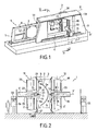
fig. 3 est une élévation montrant une configuration préférée de placement d'un outil d'usinage et d'un élément de maintien pendant l'usinage d'un panneau conformément au procédé selon l'invention. - La
fig. 4 est une perspective, à plus grande échelle, d'une forme préférée mais non exclusive, de réalisation de moyens de support d'un panneau à usiner selon l'invention. - La
fig. 5 est une vue, analogue à lafig. 3 , montrant une variante de réalisation du dispositif d'usinage selon l'invention. - La
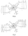
fig. 6 est une élévation, en vue de côté, d'une autre forme de réalisation du dispositif d'usinage selon l'invention. - La
fig. 7 est une vue, analogue à lafig. 5 , montrant une autre variante de réalisation du dispositif d'usinage.
- The
Fig. 1 is a schematic general perspective of a preferred embodiment of a machining device according to the invention. - The
Fig. 2 is a schematic section along plane II-II of theFig. 1 . - The
Fig. 3 is an elevation showing a preferred pattern of placement of a machining tool and a holding member during machining of a panel according to the method of the invention. - The
Fig. 4 is a perspective, on a larger scale, of a preferred but non-exclusive form of producing means for supporting a panel to be machined according to the invention. - The
Fig. 5 is a view, similar to theFig. 3 , showing an alternative embodiment of the machining device according to the invention. - The
Fig. 6 is an elevation, in side view, of another embodiment of the machining device according to the invention. - The
Fig. 7 is a view, similar to theFig. 5 , showing another alternative embodiment of the machining device.
Un dispositif d'usinage selon l'invention, tel qu'illustré à la
Afin de permettre cet usinage, le dispositif 1 comprend un châssis 3 qui, selon l'exemple illustré, est réalisé sous la forme d'une sorte de portique sensiblement vertical, définissant une fenêtre 4 à l'intérieur de laquelle le panneau à usiner vient se placer, en étant maintenu par des moyens de support 5. Selon l'exemple illustré, les moyens de support 5 sont réalisés sous la forme d'un cadre amovible susceptible d'être immobilisé, au niveau de la fenêtre 4, sur le châssis 3 par l'intermédiaire de moyens de verrouillage 6 pouvant être réalisés de toute façon appropriée.In order to allow this machining, the
Conformément à une caractéristique essentielle de l'invention, le dispositif d'usinage 1 comprend, en outre, des moyens de déplacement 10 d'au moins un outil et, selon l'exemple illustré, exactement un outil d'usinage 11, ainsi que des moyens de déplacement 12 d'au moins un et, selon l'exemple illustré, exactement un élément de maintien 13. Les moyens de déplacement 10 et 11 sont, comme le montre plus particulièrement la
Selon l'exemple illustré, les moyens de déplacement 10 de l'outil comprennent une poutre 20, mobile en translation le long d'au moins une et, selon l'exemple, deux voies de guidage 21 d'axe X supportées par le châssis 3. L'axe X des voies de guidage 21 présente alors une orientation sensiblement horizontale.According to the illustrated example, the displacement means 10 of the tool comprise a
De manière connue en soi de l'homme du métier, spécialiste dans la conception et la fabrication de machines-outils, la poutre 20 se trouve associée à des moyens moteurs, non représentés, et pilotés par une unité de commande 22, dont les différentes fonctionnalités seront précisées par la suite, étant entendu que l'unité de commande 22 est adaptée pour permettre un fonctionnement automatisé du dispositif d'usinage 1. In a manner known to those skilled in the art, specialist in the design and manufacture of machine tools, the
Les moyens de déplacement 10 de l'outil 11 comprennent, en outre, un chariot 23, mobile en translation le long d'une voie de guidage 24 d'axe Z, portée par la poutre 20. Selon l'exemple illustré, l'axe Z présente une orientation sensiblement verticale et se trouve perpendiculaire à l'axe X, de sorte que les axes X et Z définissent un plan également vertical. Le chariot 23 se trouve également associé à des moyens moteurs, non représentés, assurant son déplacement le long de la voie 24 et étant pilotés par l'unité de commande 22. The displacement means 10 of the
Les moyens de déplacement 10 comprennent, aussi, un bras 25, télescopique en translation d'axe Y qui est porté par le chariot 23. Selon l'exemple illustré, l'axe de translation Y est sensiblement perpendiculaire au plan défini par les axes X et Z de translations croisées du chariot 23. Le bras télescopique est, en outre, associé à des moyens moteurs, non représentés, pilotés par l'unité de commande 22. The displacement means 10 also comprise an
Selon l'exemple illustré, le bras télescopique 25 est équipé, au niveau de son extrémité orientée vers le châssis 3, d'un support de tête 26, mobile en rotation par rapport au bras 25 selon un axe de rotation R1 parallèle à l'axe Y et, selon l'exemple, confondu avec cet axe Y. Comme les autres organes mobiles 20, 23, 25 constitutifs des moyens de déplacement 10, le support de tête 26 est associé à des moyens moteurs non représentés et pilotés par l'unité de commande 22.According to the illustrated example, the
Enfin, les moyens de déplacement 10 comprennent une tête porte-outil 27, adaptée sur le support de tête 26, de manière à être mobile en rotation par rapport au support 26 selon un axe de rotation R2, sensiblement perpendiculaire à l'axe R1 .Bien entendu, le mouvement de rotation de la tête 27 autour de l'axe R2 se trouve associé à des moyens moteurs, non représentés, pilotés par l'unité de commande 22. Finally, the displacement means 10 comprise a
La configuration, telle que décrite précédemment, confère donc à l'outil 11, solidaire de la tête porte outil 27, cinq degrés de liberté, à savoir trois degrés de liberté en translation d'axes X, Y, Z et deux degrés de liberté en rotation d'axes R1 et R2. The configuration, as described above, thus gives the
Enfin, selon l'exemple illustré, la tête porte outils 27 est équipée de moyens moteurs, non représentés, permettant d'entraîner l'outil 11 en rotation d'usinage selon un axe Δ qui, selon l'exemple illustré à la
Selon l'invention, l'outil d'usinage 11 peut être réalisé de différentes façons et, selon l'exemple illustré, comme cela ressort plus particulièrement de la
Les moyens de déplacement 12 de l'élément de maintien 13 présentent une structure sensiblement analogue à celle des moyens de déplacement 10 de l'outil 11. Ainsi les moyens de déplacement 12 de l'outil de maintien 13 comprennent :
une poutre 30, qui est mobile en translation le long d'au moins une et, selon l'exemple, de deux voies de guidage 31 d'axe X supportées par le châssis 3 et qui est associée à des moyens moteurs pilotés, non représentés, par l'unité de commande, l'axe X' étant horizontal,un chariot 33 qui est mobile en translation le long d'une voie de guidage 34 d'axe Z' portée par la poutre 30 et qui est associé à des moyens moteurs, non représentés, pilotés par l'unité de commande 2, l'axe Z' étant sensiblement perpendiculaire à l'axe X',un bras 35 télescopique en translation, d'axe Y' porté par le chariot 33 et associé à des moyens moteurs, non représentés, pilotés par l'unité de commande 22, l'axe Y' étant sensiblement perpendiculaire au plan défini par les axes X', Z',- un support de tête 36 adapté à une extrémité du bras télescopique 35, mobile en rotation par
rapport au bras 35 selon un axe R1 parallèle à l'axe Y et associé à des moyens moteurs, non représentés, pilotés par l'unité de commande (22), - et une tête porte élément de maintien 37, adaptée sur le support de tête 36, mobile en rotation par
rapport au support 36 selon un axe R2 perpendiculaire à l'axe R'1 et associé à des moyens moteurs, non représentés, pilotés par l'unité de commande (22).
- a
beam 30, which is movable in translation along at least one and, according to the example, two X-axis guideways 31 supported by theframe 3 and which is associated with driven motor means, not shown , by the control unit, the axis X ' being horizontal, - a
carriage 33 which is movable in translation along a guideway 34 of axis Z ' carried by thebeam 30 and which is associated with motor means, not shown, controlled by thecontrol unit 2, the Z ' axis being substantially perpendicular to the axis X', - a
telescopic arm 35 in translation, of axis Y 'borne by thetrolley 33 and associated with driving means, not shown, controlled by the control unit 22, the axis Y' being substantially perpendicular to the plane defined by the axes X ', Z', - a
head support 36 adapted to an end of thetelescopic arm 35, rotatable relative to thearm 35 along an axis R 1 parallel to the axis Y and associated with motor means, not shown, controlled by the control unit (22) - and a
holder holding head 37, fitted on thehead support 36, rotatable relative to thesupport 36 along an axis R 2 perpendicular to the axis R ' 1 and associated with motor means, not shown, controlled by the control unit (22).
Conformément à l'invention, l'élément de maintien 13 peut être réalisé de toute façon appropriée et, selon l'exemple illustré, l'élément de maintien 13 présente, au niveau d'une extrémité 40 opposée à la tête de support 37, une sphère 41 destinée à définir un appui sensiblement ponctuel sur le panneau 2, comme cela apparaîtra par la suite. De manière préférée, la sphère 41 est réalisée dans un matériau élastiquement déformable, tel que, par exemple, une matière synthétique polymère ou une matière plastique. La capacité de déformation élastique de la sphère est alors mise à profit pour amortir les vibrations d'usinage. Bien entendu, la sphère pourrait également être réalisée en d'autres matériaux, tels que, par exemple, un métal comme de l'acier ou d'autres alliages métalliques adaptés. Selon l'exemple illustré, la sphère 41 se trouve sensiblement disposée à l'extrémité d'un corps 42 de forme tronconique d'axe Δ', sensiblement perpendiculaire à l'axe R'2 de rotation de la tête de support 37. La sphère 41 est alors adaptée dans le corps 42, de manière à pouvoir rouler sur le panneau 2, comme cela ressortira de la suite. Par ailleurs, de manière préférée, l'élément de maintien 13 est adapté de manière amovible sur la tête support 37, de façon à pouvoir être changé rapidement ou, encore, remplacé par un outil. A cet effet, de manière préférée, la tête 37 est, comme la tête support 27, équipée de moyens d'entraînement en rotation d'un outil autour de l'axe Δ', ces moyens d'entraînement étant pilotés par les moyens de commande 22. According to the invention, the holding
Le dispositif d'usinage ainsi constitué est alors mis en oeuvre de la façon suivante. Tout d'abord, un panneau 2 est mis en place au niveau de la fenêtre 4. A cet effet, selon l'exemple illustré, le châssis 3 présente une fenêtre latérale 50 par laquelle les moyens de support, constitués par le cadre mobile 5, sont engagés pour venir placer le plateau 2 entre l'outil 11 et l'élément de maintien 13, comme illustré à la
Une fois cet assujettissement réalisé et conformément à une caractéristique essentielle de l'invention, l'unité de commande 22 pilote le fonctionnement des moyens 10 de déplacement de l'outil 11 et des moyens de déplacement 12 de l'élément de maintien 13, de manière à venir placer l'outil 11 en fonctionnement au contact d'une face 2T, dite d'usinage, du panneau 2 au niveau d'une zone 50, dite de travail, comme cela est illustré à la
Une fois ces placements réalisés, l'unité 22 commande un déplacement coordonné de l'outil d'usinage 11 en fonctionnement et de l'élément de maintien 13 en appui sur le panneau 2, de manière à usiner, en partie au moins, la face d'usinage 2T du panneau 2. Once these placements are made, the unit 22 controls a coordinated movement of the
Conformément à une caractéristique essentielle de l'invention, l'unité de commande assure le déplacement coordonné de l'outil 11 et de l'élément de maintien 13, de manière à conserver, au cours de ce déplacement conjoint, l'opposition des zones d'appui 52 et de travail 50. Pendant ce déplacement, la sphère 41 roule alors sur la face de maintien 2M du panneau 2. C'est-à-dire que le déplacement de l'outil 11 et de l'élément de maintien 13, par rapport au panneau, possède une décomposition, selon le plan tangent et le plan normal à la surface du panneau au niveau de la zone d'usinage, dont la composante tangentielle au moins est non nulle. Le mouvement coordonné possède donc au moins une composante tangente à la surface du panneau et, dans certaines phases de l'usinage au moins, également une composante normale à la surface du panneau, comme cela est le cas pour l'outils lors de l'ajustement de la profondeur de passe notamment.According to an essential characteristic of the invention, the control unit ensures the coordinated movement of the
De manière préférée, l'unité 22 commande ces déplacements de manière à conserver, pendant toute la phase d'usinage du panneau 2, d'une part, la perpendicularité de l'axe Δ' d'appui de l'élément de maintien 13 avec la surface de la zone d'appui 52 et, d'autre part, la conjugaison de l'axe Δ' et de l'axe A de rotation de l'outil 11, de sorte que, au cours de toute la phase d'usinage et de déplacement coordonné, les axes Δ et Δ' sont confondus.Preferably, the unit 22 controls these displacements so as to maintain, throughout the machining phase of the
Ainsi, il est possible, par l'association des éléments de maintien et de l'outil d'usinage 11, d'assurer un usinage de grande précision du panneau 2, sans déformation de ce panneau. L'association de l'élément de maintien 13 et de l'outil d'usinage 11, avec les capacités de précision des moyens de commande numérique équipant l'unité de commande 22, permet alors de réaliser des usinages présentant des profondeurs de passe ou d'usinage différentes en différents points du panneau 2, en fonction des résistances recherchées pour ce dernier. Cette grande précision est rendue possible par, notamment, l'équilibre des forces d'usinage et de maintien exercées par l'outil 11 et l'élément de maintien 13 de part et d'autre du panneau 2. Thus, it is possible, by the combination of the holding elements and the
Dans une forme préférée mais non strictement nécessaire, il peut être, en vue d'obtenir une parfaite précision, envisagé de mettre en oeuvre des moyens 55 de télémétrie, par exemple des moyens de télémétrie laser permettant d'effectuer une cartographie particulièrement précise de la face de maintien 2M du panneau 2 avant usinage de ce dernier. Cette télémétrie permet ainsi d'obtenir un parfait référentiel qui permettra de connaître très précisément l'épaisseur du panneau 2 en tous points de ce dernier après usinage. En effet, l'épaisseur résiduelle sera alors déterminée par la distance entre l'extrémité de l'outil 11 et l'élément de maintien 13 et, plus particulièrement, la sphère 41 au cours de l'usinage, cette distance correspondant alors à l'épaisseur résiduelle du panneau 2 après usinage.In a preferred but not strictly necessary form, it may be, in order to obtain perfect accuracy, to consider using telemetry means 55 , for example laser telemetry means for performing a particularly accurate mapping of the 2 M holding face of the
Conformément à une autre caractéristique de l'invention, il peut également être envisagé de mettre en oeuvre des moyens de télémétrie 56 permettant de mesurer, avec précision, les coordonnées de la face de travail 2T du panneau. Ainsi, la mise en oeuvre combinée des moyens de télémétrie 55 et 56 permet d'avoir une parfaite connaissance de la géométrie du panneau 2 avant et après usinage.According to another characteristic of the invention, it may also be envisaged to implement telemetry means 56 for accurately measuring the coordinates of the working
Une fois l'usinage du panneau 2 réalisé, le cadre 5 est déverrouillé pour être retiré et permettre la mise en oeuvre d'un autre cadre.Once
L'invention ainsi constituée permet donc un travail en temps masqué et il est possible, par la mise en oeuvre de différents cadres, d'assurer un usinage de différents types de panneaux 2. The invention thus constituted allows a work in masked time and it is possible, by the implementation of different frames, to provide a machining of different types of
Il est à noter que, selon l'exemple illustré, le cadre 5 est pourvu d'une traverse 57, mobile en translation et permettant d'ajuster les dimensions utiles du cadre 5, de manière à permettre une prise en charge avec un seul type de cadre de panneau présentant différentes dimensions.It should be noted that, according to the illustrated example, the
Selon l'invention, il est également possible de mettre, au niveau de la zone de travail 50, au moins un élément de contre appui 58, tel qu'illustré à la
Les doigts 59, constitutifs de l'élément de contre appui, permettent d'éviter tout phénomène d'avalement du panneau par l'outil 11 et peuvent assurer également un amortissement de vibrations d'usinage.The
Par ailleurs, selon une autre variante de réalisation de l'invention, il est mis en oeuvre, au niveau de la tête porte-outil 27, des moyens de déplacement en translation de l'outil selon la direction Δ perpendiculaire à l'axe de rotation R2. De même, il est également mis en oeuvre, au niveau de la tête porte-élément, de maintien 37, des moyens de déplacement en translation de l'élément de maintien selon la direction Δ' perpendiculaire à l'axe de rotation R'2. Bien entendu, ces moyens de déplacement en translation sont associés à des moyens moteurs pilotés par l'unité de commande.Furthermore, according to another embodiment of the invention, it is implemented, at the level of the
Une telle configuration est particulièrement adaptée pour assurer un usinage de la coque, de manière à la rendre parfaitement conforme au modèle théorique recherché.Such a configuration is particularly suitable for machining the hull, so as to make it perfectly conform to the theoretical model sought.
Dans ce cas, l'unité de commande assurera le pilotage de l'installation sur la base du fichier de définition tridimensionnel théorique de la coque à réaliser et pilotera alors le fonctionnement des différents organes du dispositif d'usinage à cet effet.In this case, the control unit will control the installation on the basis of the theoretical three-dimensional definition file of the shell to be produced and will then control the operation of the various components of the machining device for this purpose.
Bien entendu, le dispositif d'usinage selon l'invention peut, également, être piloté dans le cadre d'un mode d'usinage, qui pourrait être qualifié de correctif, dans la mesure où, après une phase de télémétrie permettant de détecter la forme réelle de la coque, l'unité de commande pilotera le fonctionnement du dispositif pour atteindre la forme recherchée à partir de la forme réelle.Of course, the machining device according to the invention can also be controlled in the context of a machining mode, which could be qualified as a correction, insofar as, after a telemetry phase making it possible to detect the actual shape of the shell, the control unit will control the operation of the device to achieve the desired shape from the actual form.
De tels usinages en trois dimensions d'une coque sont particulièrement favorisés par la cinématique des extrémités des bras 25 et 26 et des supports d'outils 26 et d'élément de maintien, tel qu'illustré à la
Cependant, dans certaines combinaisons de mouvement, l'unité de commande éprouve des difficultés à calculer les rotations selon les axes R1, R2 et R'1, R'2 pour atteindre les zones d'usinage et d'appui.However, in certain combinations of movement, the control unit has difficulty calculating the rotations along the axes R 1 , R 2 and R ' 1 , R' 2 to reach the machining and bearing areas.
Afin d'apporter une solution à ces difficultés de calcul et de pilotage associé, l'invention propose, dans une forme de réalisation, telle que plus particulièrement illustrée à la
La
A cet effet, l'extrémité du bras 25 comprend un berceau 60, mobile en rotation autour de l'axe horizontal R1 parallèle à l'axe Y. Le support de tête 26 est alors adapté sur le berceau 60 en étant mobile par rapport à ce dernier en rotation autour de l'axe R3 perpendiculaire à l'axe R1, tandis que la tête porte-outil 27 est mobile en rotation par rapport au support 26 selon l'axe R2 perpendiculaire, à la fois, à l'axe R1 et à l'axe R3. L'ensemble comprenant l'extrémité du bras 35 sur laquelle est adapté le berceau 60, le support de tête 26, et la tête porte-outil 27 forme ce qui pourrait être appelé un équipage de tête.For this purpose, the end of the
De la même manière, l'extrémité du bras 35 comprend un berceau 61, mobile en rotation autour de l'axe horizontal R'1. In the same way, the end of the
Le support de tête 36 est adapté sur le berceau 61 en étant mobile par rapport audit berceau en rotation autour de l'axe R'3 perpendiculaire à l'axe R'1. Enfin, la tête porte-élément de maintien 37 est mobile en rotation par rapport au support 37 selon l'axe R'2 perpendiculaire aux axes de rotation R'1 et R'3. The
Dans cette configuration, il existe une redondance entre les axes R1, R2, R3, d'une part, et les axes R'1, R'2, R'3, d'autre part. L'unité de commande 22 assure alors le pilotage du dispositif d'usinage en donnant une priorité aux combinaisons de mouvement selon R2, R3 et, respectivement, R'2, R'3 par rapport aux rotations selon R1, respectivement R'1. In this configuration, there is a redundancy between the axes R 1 , R 2 , R 3 , on the one hand, and the axes R ' 1 , R' 2 , R ' 3 , on the other hand. The control unit 22 then controls the machining device giving a priority to the movement combinations according to R 2 , R 3 and, respectively, R ' 2 , R' 3 with respect to the rotations according to R 1 , respectively R ' 1 .
Bien entendu, il est également possible de prévoir, pour les formes de réalisation selon les
Claims (30)
- A method for machining a panel (2) utilising :a location of at least one machine tool (11) at the level of working area (50) of a face, so-called machining (2T), of the panel (2),a location of at least one holding element (13) at the level of a support area (52) located, on the one hand, on a face (2M), so-called holding, of the panel (2) opposite the machining face (2T) and, on the other hand, opposite relative to the panel (2) of the working area (50), the holding element (13) being adapted to act on the support area (52), and
characterised bya coordinated dislocation, at the level of the panel and according to movement having at least one component tangential to the surface of the panel, of the machine tool (11) in operation and of the holding element (13) acting on the support area (52), so as to conserve, during dislocation, the opposition of the support (52) and work (50) areas to machine part at least of the machining face. - The method for machining according to claim 1, characterised in that the holding element (13) is adapted to act on the support area by being placed in contact with the panel (2) during coordinated dislocation.
- The method for machining according to claim 1 or 2, characterised in that the holding element (13) exerts, on the panel, a support force of direction Δ' perpendicular to the surface of the support area (52).
- The method for machining according to any of claims 1 to 3, characterised in that it uses an application of at least one counter-support element (58) at the level of the working area (50).
- The method for machining according to any of claims 1 to 4, characterised in that the machine tool (11) is adapted to execute machining by snatching or removal of material and is animated by rotation movement on itself of axis Δ.
- The method for machining according to claim 5, characterised in that the holding element (13) exerts, on the support area, a directional force Δ' and in that, during machining, during coordinated dislocation of the machine tool (11) and of the holding element (13) the axes Δ and Δ' are substantially combined.
- The method for machining according to any of claims 1 to 6, characterised in that it uses dampening of the machining vibrations at least at the level of the holding element (13).
- The method for machining according to any of claims 1 to 7, characterised in that the holding element (13) and the machine tool (11) are each displaced according to at least five degrees of liberty.
- The method for machining according to claim 8, characterised in that the holding element (13) and the machine tool (11) are each displaced according to three degrees of liberty of dislocation in translation of axes X, Y, Z, respectively X', Y', Z' and two degrees of dislocation in rotation of axes R1, R2, respectively R'1, R'2, where R1, R'1 are parallel to the axes Y, Y' respectively and R2, R'2 are parallel to the planes X, Z, respectively X', Z'.
- The method for machining according to any of claims 1 to 9, characterised in that the panel to be machined (2) is placed according to a substantially vertical orientation.
- The method for machining according to any of claims 1 to 9, characterised in that the panel (2) is substantially immobile during its machining.
- The method for machining according to any of claims 1 to 11, characterised in that it uses determination of the real geometry of the holding face (2M) before machining, as well as machining of the panel (2) to a predetermined machining thickness by placing, during the coordinated machining dislocation, the holding element (13) and the machine tool (11) at a distance corresponding to the predetermined thickness.
- The method for machining according to any of claims 1 to 12, characterised in that the holding element ensures retention of the holding face (2M) of the panel without machining of this holding face (2M).
- The device for machining at least one panel (2) comprising :support means (5) of the panel (2), adapted to allow simultaneous access to two opposite faces of the panel, known as machining (2T) and holding (2M),dislocation means (10) of at least one machine tool (11),dislocation means (12) of at least one holding element (13),a control unit (22) of the dislocation means (10, 12) of the machine tool (11) and of the holding element (13), unit (22) which is adapted during a machining phase of the panel (2), to :characterised in that it further comprises a holding element (13) adapted to act on the holding face by displacing, and in that the unit (22) is adapted to- place the machine tool (11) at the level of a working area (50) of the machining face (2T) of the panel (2),- place the holding element (13) at the level of a support area (52) located on the holding surface (2M) and opposite the working area (50),
ensure coordinated dislocation, at the level of the panel and according to a movement having at least one component tangential to the surface of the panel (2) of the machine tool (11) in operation and of the holding element (13) acting on the support area, so as to conserve, during dislocation, the opposition of the support (52) and work (50) areas to machine part at least of the machining face (2T) of the panel (2). - The device according to claim 14, characterised in that the holding element (13) is adapted to be placed in contact with the panel (2) during coordinated dislocation.
- The device according to claim 14 or 15,
characterised in that the dislocation means (10, 12) of the tool (11) and of the holding element (13) each have at least five axes of dislocation, so as to impart to the tool (11) and to the holding element (13) at least five degrees of liberty. - The device according to claim 16, characterised in that the dislocation means (10, 12) of the tool (11) and of the holding element (13) each comprise three degrees of dislocation in translation of axis X, Y, Z, respectively X', Y', Z' and two degrees of dislocation in rotation of axes R1, R2 and, respectively R'1, R'2, where R1 and R'1, are parallel to the axis Y, respectively Y' and R2, R'2 are parallel to the planes defined by the axes X, Z, respectively X', Z'.
- The device according to claim 16 or 17,
characterised in that:the dislocation means (10) of the tool (11) comprise :- a beam (20) mobile in translation along at least one guide path (21) of axis x supported by a chassis (3) and associated with motor means controlled by the control unit (22),- a trolley (23) mobile in translation along a guide path (24) of axis Z, borne by the beam (20) and associated with motor means controlled by the control unit (22), the axis Z being substantially perpendicular to the axis X,- an arm (25) telescopic in translation, of axis Y borne by the trolley (23) and associated with motor means controlled by the control unit (22), the axis Y being substantially perpendicular to the plane defined by the axes X, Z,- a head support (26) adapted to an end of the telescopic arm (25) and mobile in rotation relative to the arm according to an axis R1 parallel to the axis Y and associated with motor means controlled by the control unit (22),- a head machine tool (27), adapted on the head support (26), mobile in rotation relative to the support (26) according to an axis R2 perpendicular to the axis Y and associated with motor means controlled by the control unit (22),the dislocation means (12) of the holding element (13) comprising :- a beam (30) mobile in translation along at least one guide path of axis X1 supported by the chassis (3) and associated with motor means controlled by the control unit (22),- a trolley (33) mobile in translation along a guide path (31) of axis Z', borne by the beam (30) and associated with motor means controlled by the control unit (22), the axis Z' being substantially perpendicular to the axis X',- an arm (35) telescopic in translation, of axis Y' borne by the trolley (33) and associated with motor means controlled by the control unit (22), the axis Y' being substantially perpendicular to the plane defined by the axes X', Z',- a head support (36) adapted to an end of the telescopic arm (35) and mobile in rotation relative to the arm (35) according to an axis R'1 parallel to the axis Y' and associated with motor means controlled by the control unit (22),- a head machine holding element (37), adapted on the head support (36), mobile relative to the support in rotation of axis R'2 perpendicular to the axis Y' and associated with motor means controlled by the control unit (22),and in that the support means (5) are adapted to the chassis, so as to be interposed between the dislocation means (10) of the tool (11) and the dislocation means (12) of the holding element (13). - The device according to claim 18, characterised in that:the support (26) of the head machine tool (27) is, on the one hand, adapted to a cradle (60) equipping the end of the telescopic arm (25) and being mobile in rotation about the axis R1 and, on the other hand, mobile relative to the cradle (60) in rotation about an axis R3 perpendicular to the axis R1,the support (36) of the head machine tool (37) is, on the one hand, adapted on a cradle (61) equipping the end of the telescopic arm (35) and being mobile in rotation about the axis R'1 and, on the other hand, mobile relative to the cradle (61) in rotation about an axis R'3 perpendicular to the axis R'1.
- The device according to any of claims 17 to 19, characterised in that the axes X, Z and X', Z' define substantially parallel vertical planes.
- The device according to any of claims 18 to 20, characterised in that the head machine tool (27) comprises means for driving the tool in rotation according to an axis Δ substantially perpendicular to the axis R2.
- The device according to any of claims 17 to 21, characterised in that it comprises :dislocation means in translation of the tool (11) according to a direction Δ perpendicular to the axis of rotation (R2),and dislocation means in translation of the holding element (13) according to a direction Δ' perpendicular to the axis of rotation (R'2).
- The device according to any of claims 14 to 22, characterised in that the dislocation means (10) of the tool (11) comprise at least one counter support element (55) on the machining face (2T) of the panel (2).
- The device according to any of claims 14 to 23, characterised in that it comprises damping means (41) of the machining vibrations.
- The device according to claim 24, characterised in that the damping means (41) are adapted on the dislocation means (12) of the holding element (13).
- The device according to any of claims 14 to 25, characterised in that the holding element (13) comprises at least one support sphere (41) intended to roll on the holding face (2M) of the panel (2) during machining.
- The device according to claim 25, characterised in that the support sphere (41) is made of an elastically deformable material, so as to dampen the machining vibrations.
- The device according to any of claims 14 to 27, characterised in that the support means (5) of the panel (2) are removable and in that it comprises immobilisation means (6) of the support means (5) during machining of the panel.
- The device according to claim 28, characterised in that the support means comprise a removable frame (5), equipped with fixing means for a panel to be machined.
- The device according to claim 29, characterised in that the frame comprises at least one mobile cross member, allowing adjustment of the dimensions of the frame.
Priority Applications (2)
| Application Number | Priority Date | Filing Date | Title |
|---|---|---|---|
| PL04805273T PL1689558T3 (en) | 2003-10-24 | 2004-10-22 | Method and device for machining panels |
| SI200430909T SI1689558T1 (en) | 2003-10-24 | 2004-10-22 | Method and device for machining panels |
Applications Claiming Priority (3)
| Application Number | Priority Date | Filing Date | Title |
|---|---|---|---|
| FR0312484A FR2861325B1 (en) | 2003-10-24 | 2003-10-24 | METHOD AND DEVICE FOR MACHINING PANELS |
| FR0314109A FR2861326B3 (en) | 2003-10-24 | 2003-12-02 | METHOD AND DEVICE FOR MACHINING PANELS |
| PCT/FR2004/002709 WO2005046931A1 (en) | 2003-10-24 | 2004-10-22 | Method and device for machining panels |
Publications (2)
| Publication Number | Publication Date |
|---|---|
| EP1689558A1 EP1689558A1 (en) | 2006-08-16 |
| EP1689558B1 true EP1689558B1 (en) | 2008-08-06 |
Family
ID=34424862
Family Applications (1)
| Application Number | Title | Priority Date | Filing Date |
|---|---|---|---|
| EP04805273A Active EP1689558B1 (en) | 2003-10-24 | 2004-10-22 | Method and device for machining panels |
Country Status (13)
| Country | Link |
|---|---|
| US (1) | US7682112B2 (en) |
| EP (1) | EP1689558B1 (en) |
| JP (1) | JP4742045B2 (en) |
| AT (1) | ATE403517T1 (en) |
| BR (1) | BRPI0415768B1 (en) |
| CA (1) | CA2543146C (en) |
| DE (1) | DE602004015636D1 (en) |
| ES (1) | ES2313115T3 (en) |
| FR (1) | FR2861326B3 (en) |
| PL (1) | PL1689558T3 (en) |
| RU (1) | RU2358850C2 (en) |
| SI (1) | SI1689558T1 (en) |
| WO (1) | WO2005046931A1 (en) |
Families Citing this family (50)
| Publication number | Priority date | Publication date | Assignee | Title |
|---|---|---|---|---|
| FR2865952B1 (en) * | 2004-02-10 | 2006-06-23 | Airbus France | METHOD AND DEVICE FOR THE MECHANICAL MACHINING OF FLEXIBLE PANELS, PARTICULARLY OF COMPLEX SHAPE |
| DE102004051915B4 (en) * | 2004-10-26 | 2012-11-22 | Airbus Operations Gmbh | Device for processing components for transport |
| US8549723B2 (en) * | 2007-05-11 | 2013-10-08 | The Boeing Company | Method and apparatus for squeezing parts such as fasteners |
| US8301302B2 (en) * | 2008-05-08 | 2012-10-30 | The Boeing Company | Synchronous robotic operation on a structure having a confined space |
| US20100217437A1 (en) * | 2009-02-24 | 2010-08-26 | Branko Sarh | Autonomous robotic assembly system |
| WO2010129383A2 (en) * | 2009-05-04 | 2010-11-11 | Mori Seiki Co., Ltd | System and method of synchronized machining |
| US8666546B2 (en) * | 2009-07-10 | 2014-03-04 | The Boeing Company | Autonomous robotic platform |
| DE102009050476B4 (en) * | 2009-10-23 | 2015-06-18 | Airbus S.A.S. | drilling |
| DE102010002268B4 (en) * | 2010-02-24 | 2013-10-17 | Prof. Dr.-Ing., Siegfried Schmalzried | Processing station for processing rotor blades for wind turbines |
| WO2011115244A1 (en) | 2010-03-18 | 2011-09-22 | 三菱重工業株式会社 | Molding method for plate-shaped workpiece, and molded article |
| DE102010022582A1 (en) * | 2010-06-03 | 2011-12-08 | Brötje-Automation GmbH | Method for controlling a cycled production line |
| IT1402474B1 (en) | 2010-11-05 | 2013-09-13 | Cms Spa | PLANT FOR WORKING OF SLIGHTENING OF PANELS OR THIN SHEETS BY MEANS OF MATERIAL REMOVAL |
| EP2492046B1 (en) * | 2011-02-22 | 2013-06-26 | MTU Aero Engines GmbH | Method for processing a component |
| JP5605502B2 (en) * | 2011-03-24 | 2014-10-15 | 村田機械株式会社 | Machine tool system |
| JP5916293B2 (en) | 2011-03-31 | 2016-05-11 | 三菱重工業株式会社 | Molding method of plate workpiece |
| ITTO20110420A1 (en) * | 2011-05-12 | 2012-11-13 | Fidia Spa | TOOL HOLDER HEAD FOR MACHINE TOOLS |
| KR101320027B1 (en) * | 2011-10-06 | 2013-10-21 | 주식회사 포스코 | Apparatus and method for polishing |
| JP5854811B2 (en) * | 2011-12-19 | 2016-02-09 | Dmg森精機株式会社 | Machine Tools |
| US9533371B2 (en) * | 2012-01-17 | 2017-01-03 | United Technologies Corporation | Apparatus and method for on line surface enhancement of a workpiece |
| RU2615754C2 (en) * | 2012-03-29 | 2017-04-11 | Прокопенко Дмитрий Олегович | Method for finishing panel connection butts treatment |
| ES2388972B1 (en) | 2012-04-24 | 2013-06-17 | Manuel Torres Martínez | Dynamic clamping tool for machining parts |
| DE102013006506A1 (en) * | 2013-04-16 | 2014-10-16 | Brötje-Automation GmbH | Processing plant for aircraft structural components |
| CN104227473A (en) * | 2013-06-17 | 2014-12-24 | 哈尔滨飞机工业集团有限责任公司 | Supporting device for use in machining process of parts |
| WO2015098126A1 (en) * | 2013-12-26 | 2015-07-02 | 川崎重工業株式会社 | Low-rigidity workpiece machining assistance system |
| SG11201607911SA (en) | 2014-03-28 | 2016-10-28 | Composite Cluster Singapore Pte Ltd | Freespace composite manufacturing process and device |
| RU2589957C2 (en) * | 2014-06-09 | 2016-07-10 | федеральное государственное бюджетное образовательное учреждение высшего образования "Ижевский государственный технический университет имени М.Т. Калашникова" | Method of producing flexible part |
| DE102014108629A1 (en) | 2014-06-18 | 2015-12-24 | Brötje-Automation GmbH | manufacturing system |
| DE102014113663A1 (en) | 2014-09-22 | 2016-03-24 | Broetje-Automation Gmbh | Processing plant for aircraft structural components |
| US20160138299A1 (en) * | 2014-10-20 | 2016-05-19 | John Powers, III | Multiple driver head post driving system |
| DE202015104273U1 (en) * | 2015-08-13 | 2016-11-15 | Brötje-Automation GmbH | processing station |
| US9937625B2 (en) * | 2015-12-29 | 2018-04-10 | The Boeing Company | Self-locating robots |
| ES2632166B1 (en) * | 2016-02-08 | 2018-05-08 | Manuel Torres Martinez | CURVED LAMINARY SURFACE MACHINING DEVICE |
| DE102016210089A1 (en) * | 2016-06-08 | 2017-12-14 | Airbus Operations Gmbh | Method for joining skin sections of a circumferentially closed trunk |
| US10265760B2 (en) * | 2016-08-12 | 2019-04-23 | The Boeing Company | Sliding adjustable toggle clamp |
| CN106392719B (en) * | 2016-10-14 | 2018-08-28 | 天津大学 | The flexible mirror image milling branch fastener of the pneumatic type variation rigidity of real-time thickness measuring |
| CN106334960B (en) * | 2016-10-14 | 2018-08-28 | 天津大学 | The flexibility of pneumatic type variation rigidity for mirror image milling is servo-actuated pushing tow head |
| CN106271716B (en) * | 2016-10-18 | 2018-07-24 | 中国航空工业集团公司北京航空制造工程研究所 | A kind of support device and thin-walled parts processing method for thin-walled parts processing |
| US10596691B2 (en) * | 2017-01-30 | 2020-03-24 | Stuart Topp | Devices and methods of using them to assemble two or more workpieces to each other |
| DE102017116718A1 (en) * | 2017-07-24 | 2019-01-24 | Broetje-Automation Gmbh | Processing plant for aircraft structural components |
| JP7118745B2 (en) | 2018-05-30 | 2022-08-16 | 三菱重工業株式会社 | Processing equipment and processing method |
| US11110606B2 (en) * | 2019-01-02 | 2021-09-07 | The Boeing Company | Coordinating work within a multi-robot cell |
| CN109848724B (en) * | 2019-02-19 | 2020-11-03 | 大连理工大学 | Dynamic pressure supporting device and method for machining thin-walled workpiece |
| CN109848744B (en) * | 2019-02-19 | 2020-09-11 | 大连理工大学 | Magnetic supporting device and method for thin-walled part |
| CN110039095A (en) * | 2019-04-08 | 2019-07-23 | 科德数控股份有限公司 | A kind of horizontal five axis turnover panel machining center |
| CN110560758B (en) * | 2019-08-26 | 2021-02-19 | 上海拓璞数控科技股份有限公司 | Double five-axis mirror image synchronous machining system and mirror image synchronous compensation milling method |
| EP4177166A1 (en) | 2021-11-03 | 2023-05-10 | The Boeing Company | System and method for damping machine-induced vibrations in a workpiece |
| NL2029836B1 (en) * | 2021-11-19 | 2023-06-13 | Boeing Co | System and method for damping machine-induced vibrations in a workpiece |
| US11858661B2 (en) * | 2022-02-10 | 2024-01-02 | The Boeing Company | Method of manufacturing an assembly having a nominal thickness skin panel |
| CN115415801B (en) * | 2022-10-17 | 2023-10-24 | 烟台大学 | Robot supporting device for weak-rigidity annular rotary curved surface thin-wall workpiece and machining method |
| CN117420761B (en) * | 2023-12-19 | 2024-02-13 | 合肥工业大学 | Point location layout optimization method of follow-up supporting head in mirror image milling and follow-up supporting head |
Family Cites Families (19)
| Publication number | Priority date | Publication date | Assignee | Title |
|---|---|---|---|---|
| US5248074A (en) * | 1987-12-02 | 1993-09-28 | Gemcor Engineering Corp. | Five axis riveter and system |
| US4967947A (en) * | 1988-03-23 | 1990-11-06 | Branko Sarh | Multi-function riveting/fastening machine and method of operating |
| US4885836A (en) * | 1988-04-19 | 1989-12-12 | Imta | Riveting process and apparatus |
| JPH0758184B2 (en) * | 1988-11-29 | 1995-06-21 | 日産自動車株式会社 | Three-dimensional measuring device |
| US4955119A (en) * | 1989-07-11 | 1990-09-11 | Imta | Multi-task end effector for robotic machining center |
| US4995148A (en) * | 1990-03-30 | 1991-02-26 | Imta | Robotically controlled multi-task end effector |
| US5259104A (en) * | 1990-12-21 | 1993-11-09 | The Boeing Company | Rivet recovery method |
| DE69107196T2 (en) * | 1991-04-05 | 1995-05-24 | Torres Martinez M | Machine tool device for clamping and machining. |
| US5341556A (en) * | 1991-06-28 | 1994-08-30 | The United States Of America As Represented By The Secretary Of The Air Force | Method and apparatus for manufacture of reinforced panels |
| US5611130A (en) * | 1993-06-28 | 1997-03-18 | Gemcor Engineering Corp. | Multi-position rotary head apparatus |
| US5404641A (en) * | 1993-08-16 | 1995-04-11 | Avco Corporation | Method of drilling through contiguous plate members using a robotic drill clamp |
| US5555616A (en) * | 1993-10-13 | 1996-09-17 | Gemcor Engineering Corporation | Method and apparatus for positioning of tooling efficiently |
| US5615474A (en) * | 1994-09-09 | 1997-04-01 | Gemcor Engineering Corp. | Automatic fastening machine with statistical process control |
| US5584621A (en) | 1995-06-13 | 1996-12-17 | Bertsche Engineering Corp. | Direct drive multiple axes rotary spindle head for milling machine |
| US6029352A (en) * | 1997-09-25 | 2000-02-29 | The Boeing Company | Wing panel assembly |
| US6088897A (en) * | 1998-11-24 | 2000-07-18 | The Boeing Company | Bucking bar end-effector for upsetting a rivet |
| US6430796B1 (en) * | 2000-05-03 | 2002-08-13 | The Boeing Company | Apparatus for performing automated manufacturing operations on panel-shaped workpieces |
| FR2865952B1 (en) * | 2004-02-10 | 2006-06-23 | Airbus France | METHOD AND DEVICE FOR THE MECHANICAL MACHINING OF FLEXIBLE PANELS, PARTICULARLY OF COMPLEX SHAPE |
| FR2865954B1 (en) * | 2004-02-10 | 2006-06-23 | Airbus France | METHOD AND DEVICE FOR WINDING MACHINING NON-DEVELOPABLE THIN PANELS |
-
2003
- 2003-12-02 FR FR0314109A patent/FR2861326B3/en not_active Expired - Lifetime
-
2004
- 2004-10-22 CA CA2543146A patent/CA2543146C/en not_active Expired - Fee Related
- 2004-10-22 SI SI200430909T patent/SI1689558T1/en unknown
- 2004-10-22 WO PCT/FR2004/002709 patent/WO2005046931A1/en active IP Right Grant
- 2004-10-22 JP JP2006536127A patent/JP4742045B2/en not_active Expired - Fee Related
- 2004-10-22 EP EP04805273A patent/EP1689558B1/en active Active
- 2004-10-22 RU RU2006113372/02A patent/RU2358850C2/en active
- 2004-10-22 BR BRPI0415768-0A patent/BRPI0415768B1/en not_active IP Right Cessation
- 2004-10-22 PL PL04805273T patent/PL1689558T3/en unknown
- 2004-10-22 ES ES04805273T patent/ES2313115T3/en active Active
- 2004-10-22 AT AT04805273T patent/ATE403517T1/en not_active IP Right Cessation
- 2004-10-22 US US10/576,608 patent/US7682112B2/en active Active
- 2004-10-22 DE DE602004015636T patent/DE602004015636D1/en active Active
Also Published As
| Publication number | Publication date |
|---|---|
| RU2358850C2 (en) | 2009-06-20 |
| BRPI0415768B1 (en) | 2017-07-04 |
| RU2006113372A (en) | 2007-11-27 |
| FR2861326B3 (en) | 2006-02-03 |
| ES2313115T3 (en) | 2009-03-01 |
| BRPI0415768A (en) | 2006-12-26 |
| CA2543146C (en) | 2012-08-28 |
| US7682112B2 (en) | 2010-03-23 |
| SI1689558T1 (en) | 2009-04-30 |
| EP1689558A1 (en) | 2006-08-16 |
| DE602004015636D1 (en) | 2008-09-18 |
| WO2005046931A1 (en) | 2005-05-26 |
| US20070274797A1 (en) | 2007-11-29 |
| CA2543146A1 (en) | 2005-05-26 |
| JP2007508952A (en) | 2007-04-12 |
| ATE403517T1 (en) | 2008-08-15 |
| JP4742045B2 (en) | 2011-08-10 |
| FR2861326A1 (en) | 2005-04-29 |
| PL1689558T3 (en) | 2009-04-30 |
Similar Documents
| Publication | Publication Date | Title |
|---|---|---|
| EP1689558B1 (en) | Method and device for machining panels | |
| FR2861325A1 (en) | Panel machining method for airplane, involves jointly moving drill in use and supporting unit, to maintain support and work zones in opposition for machining part of machining side | |
| CA2496770C (en) | Method and device for the mechanical machining of flexible panels, especially of complex shape | |
| EP1320438B1 (en) | Wire saw with means for producing a relative reciprocating motion between the workpiece to be sawn and the wire | |
| EP1998910B1 (en) | Device and method for joining metal sheets by means of riveting | |
| US6102777A (en) | Lapping apparatus and method for high speed lapping with a rotatable abrasive platen | |
| WO2010049645A1 (en) | Ophthalmic machine and method for machining and/or polishing a lens | |
| EP1175280B1 (en) | Method for making an ophthalmic lens surface and installation therefor | |
| EP0235602B1 (en) | Process for measuring and grinding a rail head profile | |
| FR2808464A1 (en) | GRINDING MACHINE AND METHOD FOR SHARPENING BLADES | |
| WO1998031502A1 (en) | Metal cutting machining device, with massive block and sliding column, and machine integrating this device | |
| EP0336838A1 (en) | Method and apparatus for polishing an optical component | |
| EP1689569B1 (en) | Method for piercing optical glasses with the aid of a digitally controlled drill and device for carrying out said method . | |
| CA2330338C (en) | Procedure and device used for the surface machining of a honeycomb-shaped structure | |
| JP5010120B2 (en) | Orbital polishing tool | |
| EP1522378B1 (en) | Five axis machine tool with continuous grinding wheel dressing device | |
| JP6519227B2 (en) | Processing device | |
| JPH0623580A (en) | Device for changing nozzle in laser beam machine | |
| EP0593361B1 (en) | Grinding process and -apparatus for the end-to-end welded junction of two rails | |
| JPH0890289A (en) | Method for self-travelling cutting and device therefor | |
| GB1474181A (en) | Welding method including backgrinding | |
| FR2766752A1 (en) | Machine for grinding cutting tools | |
| WO1997039844A1 (en) | Method and system for the maintenance of surfaces | |
| JPH0622795B2 (en) | Lens centering device for lens centering machine | |
| FR2642689A1 (en) | Method and device for automatically grinding the cutting edge of a tooling workpiece |
Legal Events
| Date | Code | Title | Description |
|---|---|---|---|
| PUAI | Public reference made under article 153(3) epc to a published international application that has entered the european phase |
Free format text: ORIGINAL CODE: 0009012 |
|
| 17P | Request for examination filed |
Effective date: 20060524 |
|
| AK | Designated contracting states |
Kind code of ref document: A1 Designated state(s): AT BE BG CH CY CZ DE DK EE ES FI FR GB GR HU IE IT LI LU MC NL PL PT RO SE SI SK TR |
|
| RIN1 | Information on inventor provided before grant (corrected) |
Inventor name: PANCZUK, RENE Inventor name: FOISSAC, PIERRE-YVES |
|
| DAX | Request for extension of the european patent (deleted) | ||
| 17Q | First examination report despatched |
Effective date: 20070205 |
|
| GRAP | Despatch of communication of intention to grant a patent |
Free format text: ORIGINAL CODE: EPIDOSNIGR1 |
|
| GRAS | Grant fee paid |
Free format text: ORIGINAL CODE: EPIDOSNIGR3 |
|
| GRAA | (expected) grant |
Free format text: ORIGINAL CODE: 0009210 |
|
| AK | Designated contracting states |
Kind code of ref document: B1 Designated state(s): AT BE BG CH CY CZ DE DK EE ES FI FR GB GR HU IE IT LI LU MC NL PL PT RO SE SI SK TR |
|
| REG | Reference to a national code |
Ref country code: GB Ref legal event code: FG4D Free format text: NOT ENGLISH |
|
| REG | Reference to a national code |
Ref country code: CH Ref legal event code: EP |
|
| REG | Reference to a national code |
Ref country code: IE Ref legal event code: FG4D Free format text: LANGUAGE OF EP DOCUMENT: FRENCH |
|
| REF | Corresponds to: |
Ref document number: 602004015636 Country of ref document: DE Date of ref document: 20080918 Kind code of ref document: P |
|
| REG | Reference to a national code |
Ref country code: RO Ref legal event code: EPE |
|
| REG | Reference to a national code |
Ref country code: SE Ref legal event code: TRGR |
|
| REG | Reference to a national code |
Ref country code: CH Ref legal event code: NV Representative=s name: BOVARD AG PATENTANWAELTE |
|
| PG25 | Lapsed in a contracting state [announced via postgrant information from national office to epo] |
Ref country code: AT Free format text: LAPSE BECAUSE OF FAILURE TO SUBMIT A TRANSLATION OF THE DESCRIPTION OR TO PAY THE FEE WITHIN THE PRESCRIBED TIME-LIMIT Effective date: 20080806 Ref country code: FI Free format text: LAPSE BECAUSE OF FAILURE TO SUBMIT A TRANSLATION OF THE DESCRIPTION OR TO PAY THE FEE WITHIN THE PRESCRIBED TIME-LIMIT Effective date: 20080806 |
|
| REG | Reference to a national code |
Ref country code: ES Ref legal event code: FG2A Ref document number: 2313115 Country of ref document: ES Kind code of ref document: T3 |
|
| PG25 | Lapsed in a contracting state [announced via postgrant information from national office to epo] |
Ref country code: DK Free format text: LAPSE BECAUSE OF FAILURE TO SUBMIT A TRANSLATION OF THE DESCRIPTION OR TO PAY THE FEE WITHIN THE PRESCRIBED TIME-LIMIT Effective date: 20080806 Ref country code: BG Free format text: LAPSE BECAUSE OF FAILURE TO SUBMIT A TRANSLATION OF THE DESCRIPTION OR TO PAY THE FEE WITHIN THE PRESCRIBED TIME-LIMIT Effective date: 20081106 |
|
| REG | Reference to a national code |
Ref country code: PL Ref legal event code: T3 |
|
| PG25 | Lapsed in a contracting state [announced via postgrant information from national office to epo] |
Ref country code: SK Free format text: LAPSE BECAUSE OF FAILURE TO SUBMIT A TRANSLATION OF THE DESCRIPTION OR TO PAY THE FEE WITHIN THE PRESCRIBED TIME-LIMIT Effective date: 20080806 Ref country code: PT Free format text: LAPSE BECAUSE OF FAILURE TO SUBMIT A TRANSLATION OF THE DESCRIPTION OR TO PAY THE FEE WITHIN THE PRESCRIBED TIME-LIMIT Effective date: 20090106 Ref country code: CZ Free format text: LAPSE BECAUSE OF FAILURE TO SUBMIT A TRANSLATION OF THE DESCRIPTION OR TO PAY THE FEE WITHIN THE PRESCRIBED TIME-LIMIT Effective date: 20080806 |
|
| PLBE | No opposition filed within time limit |
Free format text: ORIGINAL CODE: 0009261 |
|
| STAA | Information on the status of an ep patent application or granted ep patent |
Free format text: STATUS: NO OPPOSITION FILED WITHIN TIME LIMIT |
|
| 26N | No opposition filed |
Effective date: 20090507 |
|
| PG25 | Lapsed in a contracting state [announced via postgrant information from national office to epo] |
Ref country code: EE Free format text: LAPSE BECAUSE OF FAILURE TO SUBMIT A TRANSLATION OF THE DESCRIPTION OR TO PAY THE FEE WITHIN THE PRESCRIBED TIME-LIMIT Effective date: 20080806 |
|
| PG25 | Lapsed in a contracting state [announced via postgrant information from national office to epo] |
Ref country code: HU Free format text: LAPSE BECAUSE OF FAILURE TO SUBMIT A TRANSLATION OF THE DESCRIPTION OR TO PAY THE FEE WITHIN THE PRESCRIBED TIME-LIMIT Effective date: 20090207 Ref country code: CY Free format text: LAPSE BECAUSE OF FAILURE TO SUBMIT A TRANSLATION OF THE DESCRIPTION OR TO PAY THE FEE WITHIN THE PRESCRIBED TIME-LIMIT Effective date: 20080806 |
|
| PG25 | Lapsed in a contracting state [announced via postgrant information from national office to epo] |
Ref country code: GR Free format text: LAPSE BECAUSE OF FAILURE TO SUBMIT A TRANSLATION OF THE DESCRIPTION OR TO PAY THE FEE WITHIN THE PRESCRIBED TIME-LIMIT Effective date: 20081107 |
|
| REG | Reference to a national code |
Ref country code: CH Ref legal event code: PFA Owner name: DUFIEUX INDUSTRIE Free format text: DUFIEUX INDUSTRIE#4, RUE GASTON MONMOUSSEAU#38130 ECHIROLLES (FR) $ AIRBUS FRANCE#316, ROUTE DE BAYONNE#31060 TOULOUSE CEDEX (FR) -TRANSFER TO- DUFIEUX INDUSTRIE#4, RUE GASTON MONMOUSSEAU#38130 ECHIROLLES (FR) $ AIRBUS FRANCE#316, ROUTE DE BAYONNE#31060 TOULOUSE CEDEX (FR) |
|
| REG | Reference to a national code |
Ref country code: GB Ref legal event code: 732E Free format text: REGISTERED BETWEEN 20110721 AND 20110727 |
|
| REG | Reference to a national code |
Ref country code: ES Ref legal event code: PC2A Owner name: AIRBUS OPERATIONS SAS Effective date: 20120210 |
|
| REG | Reference to a national code |
Ref country code: DE Ref legal event code: R082 Ref document number: 602004015636 Country of ref document: DE Representative=s name: CBDL PATENTANWAELTE, DE |
|
| REG | Reference to a national code |
Ref country code: FR Ref legal event code: CJ Effective date: 20120313 Ref country code: FR Ref legal event code: CA Effective date: 20120313 Ref country code: FR Ref legal event code: CD Owner name: DUFIEUX INDUSTRIE Effective date: 20120313 Ref country code: FR Ref legal event code: CD Owner name: AIRBUS OPERATIONS, FR Effective date: 20120313 |
|
| REG | Reference to a national code |
Ref country code: DE Ref legal event code: R081 Ref document number: 602004015636 Country of ref document: DE Owner name: AIRBUS OPERATIONS SAS, FR Free format text: FORMER OWNER: DUFIEUX INDUSTRIE, AIRBUS FRANCE, , FR Effective date: 20120326 Ref country code: DE Ref legal event code: R081 Ref document number: 602004015636 Country of ref document: DE Owner name: DUFIEUX INDUSTRIE, FR Free format text: FORMER OWNER: DUFIEUX INDUSTRIE, AIRBUS FRANCE, , FR Effective date: 20120326 Ref country code: DE Ref legal event code: R082 Ref document number: 602004015636 Country of ref document: DE Representative=s name: CBDL PATENTANWAELTE, DE Effective date: 20120326 Ref country code: DE Ref legal event code: R081 Ref document number: 602004015636 Country of ref document: DE Owner name: DUFIEUX INDUSTRIE, FR Free format text: FORMER OWNERS: DUFIEUX INDUSTRIE, ECHIROLLES, FR; AIRBUS FRANCE, TOULOUSE, FR Effective date: 20120326 Ref country code: DE Ref legal event code: R081 Ref document number: 602004015636 Country of ref document: DE Owner name: AIRBUS OPERATIONS SAS, FR Free format text: FORMER OWNERS: DUFIEUX INDUSTRIE, ECHIROLLES, FR; AIRBUS FRANCE, TOULOUSE, FR Effective date: 20120326 |
|
| REG | Reference to a national code |
Ref country code: FR Ref legal event code: TP Owner name: AIRBUS HOLDING, FR Effective date: 20130322 |
|
| REG | Reference to a national code |
Ref country code: FR Ref legal event code: PLFP Year of fee payment: 12 |
|
| PGFP | Annual fee paid to national office [announced via postgrant information from national office to epo] |
Ref country code: MC Payment date: 20150918 Year of fee payment: 12 Ref country code: IE Payment date: 20150923 Year of fee payment: 12 Ref country code: LU Payment date: 20150923 Year of fee payment: 12 |
|
| PGFP | Annual fee paid to national office [announced via postgrant information from national office to epo] |
Ref country code: SI Payment date: 20150731 Year of fee payment: 12 |
|
| REG | Reference to a national code |
Ref country code: FR Ref legal event code: PLFP Year of fee payment: 13 |
|
| PGFP | Annual fee paid to national office [announced via postgrant information from national office to epo] |
Ref country code: CH Payment date: 20161014 Year of fee payment: 13 |
|
| PGFP | Annual fee paid to national office [announced via postgrant information from national office to epo] |
Ref country code: RO Payment date: 20161017 Year of fee payment: 13 Ref country code: PL Payment date: 20161005 Year of fee payment: 13 |
|
| PG25 | Lapsed in a contracting state [announced via postgrant information from national office to epo] |
Ref country code: MC Free format text: LAPSE BECAUSE OF NON-PAYMENT OF DUE FEES Effective date: 20161031 |
|
| REG | Reference to a national code |
Ref country code: IE Ref legal event code: MM4A |
|
| PG25 | Lapsed in a contracting state [announced via postgrant information from national office to epo] |
Ref country code: LU Free format text: LAPSE BECAUSE OF NON-PAYMENT OF DUE FEES Effective date: 20161022 Ref country code: SI Free format text: LAPSE BECAUSE OF NON-PAYMENT OF DUE FEES Effective date: 20161023 |
|
| REG | Reference to a national code |
Ref country code: SI Ref legal event code: KO00 Effective date: 20170727 |
|
| REG | Reference to a national code |
Ref country code: FR Ref legal event code: PLFP Year of fee payment: 14 |
|
| PG25 | Lapsed in a contracting state [announced via postgrant information from national office to epo] |
Ref country code: IE Free format text: LAPSE BECAUSE OF NON-PAYMENT OF DUE FEES Effective date: 20161022 |
|
| PGFP | Annual fee paid to national office [announced via postgrant information from national office to epo] |
Ref country code: SE Payment date: 20171016 Year of fee payment: 14 |
|
| REG | Reference to a national code |
Ref country code: CH Ref legal event code: PL |
|
| PG25 | Lapsed in a contracting state [announced via postgrant information from national office to epo] |
Ref country code: LI Free format text: LAPSE BECAUSE OF NON-PAYMENT OF DUE FEES Effective date: 20171031 Ref country code: CH Free format text: LAPSE BECAUSE OF NON-PAYMENT OF DUE FEES Effective date: 20171031 |
|
| REG | Reference to a national code |
Ref country code: FR Ref legal event code: PLFP Year of fee payment: 15 |
|
| PG25 | Lapsed in a contracting state [announced via postgrant information from national office to epo] |
Ref country code: RO Free format text: LAPSE BECAUSE OF NON-PAYMENT OF DUE FEES Effective date: 20171022 |
|
| PG25 | Lapsed in a contracting state [announced via postgrant information from national office to epo] |
Ref country code: PL Free format text: LAPSE BECAUSE OF NON-PAYMENT OF DUE FEES Effective date: 20171022 |
|
| REG | Reference to a national code |
Ref country code: SE Ref legal event code: EUG |
|
| PG25 | Lapsed in a contracting state [announced via postgrant information from national office to epo] |
Ref country code: SE Free format text: LAPSE BECAUSE OF NON-PAYMENT OF DUE FEES Effective date: 20181023 |
|
| REG | Reference to a national code |
Ref country code: NL Ref legal event code: MM Effective date: 20191101 |
|
| PG25 | Lapsed in a contracting state [announced via postgrant information from national office to epo] |
Ref country code: NL Free format text: LAPSE BECAUSE OF NON-PAYMENT OF DUE FEES Effective date: 20191101 |
|
| PGFP | Annual fee paid to national office [announced via postgrant information from national office to epo] |
Ref country code: TR Payment date: 20201001 Year of fee payment: 17 |
|
| PGFP | Annual fee paid to national office [announced via postgrant information from national office to epo] |
Ref country code: IT Payment date: 20201008 Year of fee payment: 17 Ref country code: DE Payment date: 20201009 Year of fee payment: 17 Ref country code: GB Payment date: 20201015 Year of fee payment: 17 Ref country code: ES Payment date: 20201103 Year of fee payment: 17 |
|
| PGFP | Annual fee paid to national office [announced via postgrant information from national office to epo] |
Ref country code: BE Payment date: 20201015 Year of fee payment: 17 |
|
| REG | Reference to a national code |
Ref country code: DE Ref legal event code: R119 Ref document number: 602004015636 Country of ref document: DE |
|
| REG | Reference to a national code |
Ref country code: BE Ref legal event code: MM Effective date: 20211031 |
|
| GBPC | Gb: european patent ceased through non-payment of renewal fee |
Effective date: 20211022 |
|
| PG25 | Lapsed in a contracting state [announced via postgrant information from national office to epo] |
Ref country code: GB Free format text: LAPSE BECAUSE OF NON-PAYMENT OF DUE FEES Effective date: 20211022 Ref country code: DE Free format text: LAPSE BECAUSE OF NON-PAYMENT OF DUE FEES Effective date: 20220503 Ref country code: BE Free format text: LAPSE BECAUSE OF NON-PAYMENT OF DUE FEES Effective date: 20211031 |
|
| PG25 | Lapsed in a contracting state [announced via postgrant information from national office to epo] |
Ref country code: IT Free format text: LAPSE BECAUSE OF NON-PAYMENT OF DUE FEES Effective date: 20211022 |
|
| REG | Reference to a national code |
Ref country code: ES Ref legal event code: FD2A Effective date: 20230203 |
|
| PG25 | Lapsed in a contracting state [announced via postgrant information from national office to epo] |
Ref country code: ES Free format text: LAPSE BECAUSE OF NON-PAYMENT OF DUE FEES Effective date: 20211023 |
|
| PGFP | Annual fee paid to national office [announced via postgrant information from national office to epo] |
Ref country code: FR Payment date: 20230920 Year of fee payment: 20 |