EP1688659B1 - Dispositif de joint universel entre un support d'appareil et un bras de support ou une console - Google Patents
Dispositif de joint universel entre un support d'appareil et un bras de support ou une console Download PDFInfo
- Publication number
- EP1688659B1 EP1688659B1 EP06001287A EP06001287A EP1688659B1 EP 1688659 B1 EP1688659 B1 EP 1688659B1 EP 06001287 A EP06001287 A EP 06001287A EP 06001287 A EP06001287 A EP 06001287A EP 1688659 B1 EP1688659 B1 EP 1688659B1
- Authority
- EP
- European Patent Office
- Prior art keywords
- shank
- tensioning
- ball joint
- ball
- screw
- Prior art date
- Legal status (The legal status is an assumption and is not a legal conclusion. Google has not performed a legal analysis and makes no representation as to the accuracy of the status listed.)
- Not-in-force
Links
- 230000007246 mechanism Effects 0.000 claims abstract description 15
- 230000013011 mating Effects 0.000 claims description 4
- 238000006073 displacement reaction Methods 0.000 description 2
- 239000000969 carrier Substances 0.000 description 1
- 210000000078 claw Anatomy 0.000 description 1
- 230000008878 coupling Effects 0.000 description 1
- 238000010168 coupling process Methods 0.000 description 1
- 238000005859 coupling reaction Methods 0.000 description 1
- 210000003811 finger Anatomy 0.000 description 1
- 238000010438 heat treatment Methods 0.000 description 1
- 230000004048 modification Effects 0.000 description 1
- 238000012986 modification Methods 0.000 description 1
- 210000003813 thumb Anatomy 0.000 description 1
- 230000000007 visual effect Effects 0.000 description 1
Images


Classifications
-
- F—MECHANICAL ENGINEERING; LIGHTING; HEATING; WEAPONS; BLASTING
- F16—ENGINEERING ELEMENTS AND UNITS; GENERAL MEASURES FOR PRODUCING AND MAINTAINING EFFECTIVE FUNCTIONING OF MACHINES OR INSTALLATIONS; THERMAL INSULATION IN GENERAL
- F16C—SHAFTS; FLEXIBLE SHAFTS; ELEMENTS OR CRANKSHAFT MECHANISMS; ROTARY BODIES OTHER THAN GEARING ELEMENTS; BEARINGS
- F16C11/00—Pivots; Pivotal connections
- F16C11/04—Pivotal connections
- F16C11/10—Arrangements for locking
- F16C11/103—Arrangements for locking frictionally clamped
- F16C11/106—Arrangements for locking frictionally clamped for ball joints
-
- F—MECHANICAL ENGINEERING; LIGHTING; HEATING; WEAPONS; BLASTING
- F16—ENGINEERING ELEMENTS AND UNITS; GENERAL MEASURES FOR PRODUCING AND MAINTAINING EFFECTIVE FUNCTIONING OF MACHINES OR INSTALLATIONS; THERMAL INSULATION IN GENERAL
- F16C—SHAFTS; FLEXIBLE SHAFTS; ELEMENTS OR CRANKSHAFT MECHANISMS; ROTARY BODIES OTHER THAN GEARING ELEMENTS; BEARINGS
- F16C11/00—Pivots; Pivotal connections
- F16C11/04—Pivotal connections
- F16C11/06—Ball-joints; Other joints having more than one degree of angular freedom, i.e. universal joints
- F16C11/0661—Ball-joints; Other joints having more than one degree of angular freedom, i.e. universal joints the two co-operative parts each having both convex and concave interfaces
-
- F—MECHANICAL ENGINEERING; LIGHTING; HEATING; WEAPONS; BLASTING
- F16—ENGINEERING ELEMENTS AND UNITS; GENERAL MEASURES FOR PRODUCING AND MAINTAINING EFFECTIVE FUNCTIONING OF MACHINES OR INSTALLATIONS; THERMAL INSULATION IN GENERAL
- F16M—FRAMES, CASINGS OR BEDS OF ENGINES, MACHINES OR APPARATUS, NOT SPECIFIC TO ENGINES, MACHINES OR APPARATUS PROVIDED FOR ELSEWHERE; STANDS; SUPPORTS
- F16M11/00—Stands or trestles as supports for apparatus or articles placed thereon Stands for scientific apparatus such as gravitational force meters
- F16M11/02—Heads
- F16M11/04—Means for attachment of apparatus; Means allowing adjustment of the apparatus relatively to the stand
- F16M11/06—Means for attachment of apparatus; Means allowing adjustment of the apparatus relatively to the stand allowing pivoting
- F16M11/12—Means for attachment of apparatus; Means allowing adjustment of the apparatus relatively to the stand allowing pivoting in more than one direction
- F16M11/14—Means for attachment of apparatus; Means allowing adjustment of the apparatus relatively to the stand allowing pivoting in more than one direction with ball-joint
-
- F—MECHANICAL ENGINEERING; LIGHTING; HEATING; WEAPONS; BLASTING
- F16—ENGINEERING ELEMENTS AND UNITS; GENERAL MEASURES FOR PRODUCING AND MAINTAINING EFFECTIVE FUNCTIONING OF MACHINES OR INSTALLATIONS; THERMAL INSULATION IN GENERAL
- F16M—FRAMES, CASINGS OR BEDS OF ENGINES, MACHINES OR APPARATUS, NOT SPECIFIC TO ENGINES, MACHINES OR APPARATUS PROVIDED FOR ELSEWHERE; STANDS; SUPPORTS
- F16M11/00—Stands or trestles as supports for apparatus or articles placed thereon Stands for scientific apparatus such as gravitational force meters
- F16M11/20—Undercarriages with or without wheels
- F16M11/2007—Undercarriages with or without wheels comprising means allowing pivoting adjustment
- F16M11/2035—Undercarriages with or without wheels comprising means allowing pivoting adjustment in more than one direction
- F16M11/2064—Undercarriages with or without wheels comprising means allowing pivoting adjustment in more than one direction for tilting and panning
-
- F—MECHANICAL ENGINEERING; LIGHTING; HEATING; WEAPONS; BLASTING
- F16—ENGINEERING ELEMENTS AND UNITS; GENERAL MEASURES FOR PRODUCING AND MAINTAINING EFFECTIVE FUNCTIONING OF MACHINES OR INSTALLATIONS; THERMAL INSULATION IN GENERAL
- F16M—FRAMES, CASINGS OR BEDS OF ENGINES, MACHINES OR APPARATUS, NOT SPECIFIC TO ENGINES, MACHINES OR APPARATUS PROVIDED FOR ELSEWHERE; STANDS; SUPPORTS
- F16M13/00—Other supports for positioning apparatus or articles; Means for steadying hand-held apparatus or articles
- F16M13/02—Other supports for positioning apparatus or articles; Means for steadying hand-held apparatus or articles for supporting on, or attaching to, an object, e.g. tree, gate, window-frame, cycle
- F16M13/022—Other supports for positioning apparatus or articles; Means for steadying hand-held apparatus or articles for supporting on, or attaching to, an object, e.g. tree, gate, window-frame, cycle repositionable
-
- F—MECHANICAL ENGINEERING; LIGHTING; HEATING; WEAPONS; BLASTING
- F16—ENGINEERING ELEMENTS AND UNITS; GENERAL MEASURES FOR PRODUCING AND MAINTAINING EFFECTIVE FUNCTIONING OF MACHINES OR INSTALLATIONS; THERMAL INSULATION IN GENERAL
- F16M—FRAMES, CASINGS OR BEDS OF ENGINES, MACHINES OR APPARATUS, NOT SPECIFIC TO ENGINES, MACHINES OR APPARATUS PROVIDED FOR ELSEWHERE; STANDS; SUPPORTS
- F16M2200/00—Details of stands or supports
- F16M2200/02—Locking means
- F16M2200/021—Locking means for rotational movement
- F16M2200/022—Locking means for rotational movement by friction
Definitions
- the invention relates to a universal joint assembly for connecting a device holder or a device holder mounting plate or the like. With a support arm or a console.
- Mobile devices such as personal digital assistants (PDAs), navigation devices, cell phones, and the like are used in automobiles, desks, or other locations using equipment carriers having a console or support arm connected thereto via a linkage mechanism a device holder or a mounting plate is connected to its receptacle, so that the device in question can be set in a convenient for viewing the visual display of the device and for operating the device position.
- PDAs personal digital assistants
- navigation devices such as cell phones, and the like
- cell phones such as cell phones, and the like
- equipment carriers having a console or support arm connected thereto via a linkage mechanism a device holder or a mounting plate is connected to its receptacle, so that the device in question can be set in a convenient for viewing the visual display of the device and for operating the device position.
- Universal joints for this purpose are known both in the form of two successive hinges arranged at right angles to each other and in the form of ball joints with a spherically curved cup and a spherical segment-shaped joint part.
- the linkage mechanism In known ball joint mechanisms, the necessary clamping voltage is generated by a screw is screwed from the mounting plate or device holder side forth in the pan area of the hinge mechanism and tightened to the extent necessary.
- the joint parts are substantially all made of plastic, which is known to have a large coefficient of thermal expansion, there are especially when used in vehicles because of the large temperature changes occurring there, for example during heating the internal temperature of a vehicle standing in the sun in the summer, considerable problems in that the clamping voltage loosens so that the device holder can not maintain its set position. This is not only annoying, because it significantly affects the use of the device, but also the fact that the necessary retightening only with the help of a suitable screwdriver and after removing at least the device holder, if not even the mounting plate, is possible.
- a universal joint assembly according to the preamble of claim 1 is known from GB 2 096 234 A known.
- a swivel mount for a screen monitor is known, with a stand base, which is formed with a ball socket, further with a holder for the screen monitor; which is designed as a spherical shell and is seated in the ball socket, and a spans from above against the ball socket and with a shaft disposed thereon passes through an opening of the spherical shell and cooperates with an arranged behind the ball socket actuator in the form of a pinch wheel.
- the opening in the ball shell is formed in the form of a diametrically extending slot, which only allows pivoting in a plane, but also allows rotation about the shaft axis.
- the invention aims at improving a deratigen universal joint assembly with respect to the needs of a PDA holder.
- the Figures 1 and 2 show a hinge assembly according to the invention in the embodiment of the connection of a device holder mounting plate 1 with a short pivot arm 2 as an end member of a device carrier, which is not shown otherwise.
- the device holder mounting plate 1 has an array of angular claws 11, which cooperates with corresponding locking slots of the device holder, not shown, and forms with this a quick coupling for releasably attaching the device holder.
- the swing arm 2, which is shown very briefly in the drawing, can of course have any length and has a rear fork-shaped hinge member 21 which cooperates with a corresponding counter-element of a hinge mechanism.
- the ball joint assembly between the Adjusthaltermontageplatte 1 and the pivot arm 2 consists of a rear side of the mounting plate 1 arranged ball cup-shaped ball joint element 12, arranged at the front end of the pivot arm 2 ball segment pan 22, and a joint clamping mechanism third
- the joint tensioning mechanism 3 has a projecting in the ball segment cup 22 hollow pin 31, a mounted on the free end spherical segment clamping body 32, a passing from the clamping body 32 through the hollow pin 31 screw 33 with a corresponding recess of the clamping body 32 rotatably seated screw head 34, a behind the ball segment socket 22 on the screw 33 seated nut 35 with a mother this rotatably receiving thumb wheel 36.
- the clamping body on its side facing the pan 22 has a cylindrical blind hole which receives the free end of the hollow pin 31 and allows a relative axial displacement between the clamping body 32 and the hollow pin 31 over a certain distance.
- the spherical shell-shaped ball joint part 12 is thus, as you can see, taken between the pan 22 and the clamping body 32 and clamped between them.
- the ball joint element 12 has, as shown FIG. 2 shows, a large central opening 13, through which the hollow pin 31 passes and which is dimensioned so that the necessary all-round pivoting range of the mounting plate 1 is achieved.
- the ball joint assembly can be clamped at any time locked on the mounting plate 1 device holder without any tools, re-tensioned or loosened for adjustment.
- the setting wheel 36 is disposed within a planar frame formed by the pivot arm 2 and there to take on two opposite sides easily with two fingers. It is understood that the pivot arm 2 may be formed as such in any manner or replaced by another member of a device carrier.
- FIG. 3 a complete equipment rack 4 with a column 41, a suction pad 42 arranged thereon with suction actuating mechanism arranged inside the column, and a telescopic arm 44 connected to the column 41 via a hinge joint arrangement 43 with two hinge axes offset by 90 °, to the free end of which is a holder mounting plate 1 one in their details described ball joint assembly with a joint clamping mechanism 3 is connected.
- the ball joint assembly with its clamping mechanism can also be designed such that the adjusting wheel 36 is connected to the head of a screw which cooperates with a nut inserted in the clamping body 32.
- the thumbwheel 36 may be replaced by a pivot lever which, like the thumbwheel 36 about the longitudinal axis of the screw 33 and the pivot arm 2 or the ball joint assembly is pivotally and cooperates with a screw 33 replacing coarse thread or the like, or the pivot lever and the ball socket 22 can cooperate with each other via a ramp located either on the pivoting lever or on the ball socket, which converts the pivoting rotary movement into an axial relative movement between pivot lever and ball socket or between pivoting lever and clamping body 32 for clamping the ball joint arrangement together.
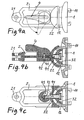
- FIGS. 4a to 4c show an embodiment with an eccentric pivot lever 4, which is pivotable about a transverse to the longitudinal axis of the ball joint assembly and the pivot arm 2 extending axis between a release position and a clamping position.
- a running from the clamping body 32 through the ball joint elements shaft 41 is connected at its pivot lever end via a transverse pin 42 with the pivot lever 4, as shown FIG. 4b is apparent.
- the end of the shaft 41 is received in a recess 43 of the pivot lever 4, which is the pivoting range of the pivot lever 4 (in FIG. 4a shown) has corresponding angular extent, as in Figure 4c is apparent.
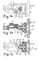
- a pivotable about the longitudinal axis of the ball joint assembly actuating lever 5 is provided, which cooperates with the end face of an outgoing from the clamping body 32 shaft 51.
- the actuating lever 5 is pivotable about a transverse axis 52 laterally offset from the longitudinal axis of the ball joint arrangement or the shaft 51.
- a cup spring assembly 53 Above the shaft 51 behind the ball socket 22 sits a cup spring assembly 53 which is held by a transverse pin 54 which extends through the free end of the shaft 51. This disc spring assembly biases the shaft 51 and thus the clamping body 32 in the clamping position.
- the shaft 51 is axially displaced against the bias by the cup spring assembly 53 in the sense of loosening the tension of the ball joint assembly.
- the plate spring package 53 Upon return movement of the actuating lever 5 in its release position, the plate spring package 53 again causes the automatic bracing and thus locking the ball joint assembly.
- a sliding wedge 6 which cooperates with a shaft which is formed in the illustrated embodiment by a screw 61 and a block 62.
- the screw 61 connects the clamping body 32 with the block 62.
- the sliding wedge passes through a corresponding transverse recess of the block 62, as in the Figures 6b and 6c is shown in two mutually offset by 90 ° views.
- the sliding wedge on its side facing away from the hinge assembly side has a slightly oblique edge surface 63, which cooperates with a correspondingly formed, slightly oblique mating surface of the recess of the block 62.
Claims (10)
- Dispositif de joint universel entre le composant terminal (2) d'un porte-appareil et une platine de montage de support d'appareil (1) ou un support d'appareil, dans lequel un élément de joint à rotule (22) disposé sur le composant terminal (2) coopère avec un élément de joint à rotule (12) disposé sur la platine de montage du support d'appareil ou sur le support d'appareil et les deux éléments de joint à rotule (12, 22) peuvent être serrés ensemble de manière solidaire par friction au moyen d'un mécanisme de serrage de joint (3),
le mécanisme de serrage de joint (3) présentant un corps de serrage (32) disposé côté platine de montage ou côté support d'appareil, destiné à serrer l'élément de joint à rotule (12) côté platine de montage ou côté support d'appareil, réalisé sous la forme de coussinet sphérique, contre l'élément de joint à rotule (22) côté composant terminal, réalisé sous la forme de cuvette sphérique, et une tige (33 ; 41 ; 51 ; 61) allant du corps de serrage (32) au composant terminal (2) à travers les deux éléments de joint à rotule (12, 22), ainsi qu'un organe d'actionnement (36 ; 4 ; 5 ; 6) disposé derrière l'élément de joint à rotule (22) côté composant terminal qui coopère avec la tige au sens de la production d'un mouvement relatif axial entre lui et le corps de serrage (32) dans le but de serrer ensemble ou de desserrer les éléments de joint à rotule (12, 22) par le corps de serrage (32),
et l'élément de joint à rotule (12) côté platine de montage ou côté support d'appareil, réalisé sous la forme de coussinet sphérique, présentant une grande ouverture centrale (13) par laquelle passe la tige (33 ; 41 ; 51 ; 61) et dont le jeu détermine la plage de pivotement de cet élément de joint à rotule (12),
caractérisé en ce que l'élément de joint à rotule (22) réalisé sous la forme de cuvette sphérique présente un tourillon creux (31) guidant la tige, faisant saillie axialement, à l'extrémité libre duquel le corps de serrage (32) est guidé de façon mobile axialement. - Dispositif de joint universel selon la revendication 1, dans lequel le mécanisme de serrage de joint (3) présente un accouplement vis-écrou dont l'un des éléments, vis ou écrou, est relié au corps de serrage (32) de manière résistant à la rotation et l'autre élément, écrou ou vis, est relié de manière résistant à la rotation à une roue de réglage (36) actionnable avec le doigt, formant l'organe d'actionnement, la vis (33) formant la tige mentionnée.
- Dispositif de joint universel selon la revendication 2, dans lequel la vis (33, 34) est reliée au corps de serrage (32) de manière résistant à la rotation et la roue de réglage (36) est reliée de manière résistant à la rotation à l'écrou (35) qui est situé sur le boulon fileté (33) derrière l'élément de joint à rotule (22) côté composant terminal.
- Dispositif de joint universel selon la revendication 3, dans lequel la vis (33, 34) présente une tête de vis (34) logée dans le corps de serrage (32) de manière résistant à la rotation et de manière solidaire avec correspondance de forme.
- Dispositif de joint universel selon la revendication 1, dans lequel la tige (41) est reliée par son extrémité éloignée du corps de serrage (32) à un levier à excentrique (4) qui peut pivoter entre une position de desserrage et une position de serrage autour d'un axe de pivotement situé transversalement à l'axe longitudinal de la tige.
- Dispositif de joint universel selon la revendication 5, dans lequel le levier à excentrique (4) est relié à la tige par l'intermédiaire d'une goupille transversale (42) définissant aussi son axe de pivotement, traversant l'extrémité de la tige (41), et s'appuie avec une came excentrique sur une surface opposée située sur la face arrière de la cuvette sphérique (22) ou d'une pièce reliée à celle-ci.
- Dispositif de joint universel selon la revendication 1, dans lequel le corps de serrage (32) est soumis à une tension initiale dans sa position de serrage au moyen d'une tension initiale par ressort agissant sur la tige (51) et l'organe d'actionnement a une position de repos correspondant à la position de serrage du corps de serrage (32) et, lors du déplacement à partir de celle-ci vers une position de travail qui correspond à la position de desserrage du corps de serrage (32), agit sur l'extrémité de la tige éloignée du corps de serrage (32) en sens inverse de la tension initiale par ressort.
- Dispositif de joint universel selon la revendication 7, dans lequel la tension initiale par ressort est produite par un ensemble de rondelles Belleville (53) disposé de manière concentrique sur la tige (51) et traversé par celle-ci, ledit ensemble s'appuyant d'une part sur la face arrière de la cuvette sphérique (22) et d'autre part sur un élément de butée (54) relié à l'extrémité libre de la tige.
- Dispositif de joint universel selon la revendication 7 ou 8, dans lequel l'organe d'actionnement est un levier pivotant (5) qui peut pivoter autour d'un axe de pivotement (52) s'étendant transversalement à l'axe longitudinal de la tige et décalé latéralement par rapport à celui-ci et coopère avec la surface d'extrémité de la tige (51) par l'intermédiaire d'un élément de levier de telle sorte que le levier pivotant prend, dans sa position de travail correspondant à la position de desserrage du corps de serrage (32), une position stable ou instable.
- Dispositif de joint universel selon la revendication 1, dans lequel l'organe d'actionnement est une clavette coulissante (6) mobile transversalement à la tige (61, 62) entre une position d'extrémité correspondant à la position de serrage du corps de serrage (32) et une position d'extrémité correspondant à la position de desserrage du corps de serrage, ladite clavette coopérant à la manière d'un mécanisme à clavette avec une surface opposée formée sur la tige ou sur la cuvette sphérique (22).
Priority Applications (1)
| Application Number | Priority Date | Filing Date | Title |
|---|---|---|---|
| US11/389,611 US7241069B2 (en) | 2005-02-07 | 2006-03-24 | Universal joint arrangement between an apparatus holder and a support arm or a console |
Applications Claiming Priority (1)
| Application Number | Priority Date | Filing Date | Title |
|---|---|---|---|
| DE200520001986 DE202005001986U1 (de) | 2005-02-07 | 2005-02-07 | Universalgelenkanordnung zwischen einem Gerätehalter und einem Tragarm oder einer Konsole |
Publications (3)
| Publication Number | Publication Date |
|---|---|
| EP1688659A2 EP1688659A2 (fr) | 2006-08-09 |
| EP1688659A3 EP1688659A3 (fr) | 2006-11-22 |
| EP1688659B1 true EP1688659B1 (fr) | 2009-12-16 |
Family
ID=34442769
Family Applications (1)
| Application Number | Title | Priority Date | Filing Date |
|---|---|---|---|
| EP06001287A Not-in-force EP1688659B1 (fr) | 2005-02-07 | 2006-01-21 | Dispositif de joint universel entre un support d'appareil et un bras de support ou une console |
Country Status (4)
| Country | Link |
|---|---|
| US (1) | US20060175501A1 (fr) |
| EP (1) | EP1688659B1 (fr) |
| AT (1) | ATE452313T1 (fr) |
| DE (2) | DE202005001986U1 (fr) |
Cited By (3)
| Publication number | Priority date | Publication date | Assignee | Title |
|---|---|---|---|---|
| CN102518918A (zh) * | 2011-12-27 | 2012-06-27 | 天津大学 | 一种用于工业摄像机的调节支架 |
| DE202013007384U1 (de) | 2012-08-29 | 2013-09-12 | Harald Richter | Geräteträgerkonsole für im Lenkerbereich von Fahrrädern montierbare Mobiltelefone und ähnliche Geräte |
| DE102013014921B4 (de) | 2013-09-11 | 2020-04-23 | Harald Richter | Geräteträger mit Saugfuß und Schwenkarm für Mobiltelefone |
Families Citing this family (17)
| Publication number | Priority date | Publication date | Assignee | Title |
|---|---|---|---|---|
| US7028961B1 (en) | 2003-05-30 | 2006-04-18 | Csav, Inc. | Self-balancing adjustable flat panel mounting system |
| US7380760B2 (en) * | 2003-05-30 | 2008-06-03 | Csav, Inc. | Self-balancing adjustable mounting system with friction adjustment |
| US20070049128A1 (en) * | 2005-08-30 | 2007-03-01 | Paul Brassard | Mounting structure |
| DE202005021680U1 (de) * | 2005-09-09 | 2009-03-19 | Bury Sp.Z.O.O | Navigationseinrichtung |
| US20080190978A1 (en) * | 2007-02-14 | 2008-08-14 | Paul Brassard | Mounting apparatus |
| CN101730815B (zh) * | 2007-06-29 | 2014-10-22 | 德雷格医疗系统股份有限公司 | 用于监视器和其他装置的倾斜和旋转安装装置 |
| DE102007060543B3 (de) * | 2007-12-13 | 2008-10-02 | Bühler, Martin | Tisch, insbesondere Steh- oder Bistrot-Tisch |
| US20090294608A1 (en) * | 2008-05-30 | 2009-12-03 | Paul Brassard | Mounting Structure |
| FR2941280B1 (fr) * | 2009-01-20 | 2013-07-19 | Airbus France | Dispositif d'attache pour des tuyaux hydrauliques flexibles |
| CN103062589A (zh) * | 2011-10-21 | 2013-04-24 | 鸿富锦精密工业(深圳)有限公司 | 支撑装置 |
| DE102013005766A1 (de) * | 2012-10-26 | 2014-05-15 | Tormaxx Gmbh | Halterung und Set mit einer Halterung |
| EP3098463B1 (fr) * | 2015-05-26 | 2018-03-14 | Airbus Operations GmbH | Joint rotatif, kit de construction d'ossature et procédé de fabrication d'un joint rotatif |
| EP3135833B1 (fr) * | 2015-08-27 | 2019-05-08 | Airbus Operations GmbH | Joint rotatif, kit de construction de structure en treillies avec des joints rotatifs de structure et procédé de fabrication d'un joint rotatif |
| KR20190041065A (ko) | 2017-10-12 | 2019-04-22 | 에이치피프린팅코리아 유한회사 | 힌지 장치 |
| CA3040853A1 (fr) * | 2018-04-21 | 2019-10-21 | David Robertson | Un appareil de protection contre les tonneaux |
| CN112682640B (zh) * | 2020-12-21 | 2022-08-19 | 内蒙古师范大学 | 一种用于数字媒体艺术设计拍摄装置的稳定滑动机构 |
| CN215003173U (zh) * | 2021-01-06 | 2021-12-03 | 叶小惠 | 万向支撑机构 |
Family Cites Families (11)
| Publication number | Priority date | Publication date | Assignee | Title |
|---|---|---|---|---|
| US86173A (en) * | 1869-01-26 | Improved baiiit-and-socket joint | ||
| GB155084A (en) * | 1919-10-27 | 1920-12-16 | Edward Moulds | An improved adjustable vice |
| US1446164A (en) * | 1920-04-01 | 1923-02-20 | D Eyraud Louis | Universal mounting device |
| US1909526A (en) * | 1932-03-23 | 1933-05-16 | Robert N Falge | Rear view mirror holder |
| US2126389A (en) * | 1936-10-19 | 1938-08-09 | Thompson Prod Inc | Ball joint |
| US3477678A (en) * | 1966-12-01 | 1969-11-11 | William M Icke | Universal vehicle sun visor mount |
| US4088129A (en) * | 1976-11-15 | 1978-05-09 | Digiulio Mario | Appliance for foot orthosis |
| SE420012B (sv) * | 1978-07-13 | 1981-09-07 | Gunnar M T Kjellstrand | Koppling av kulledstyp |
| GB2096234B (en) * | 1981-04-03 | 1985-02-20 | Mouldmaking Design Centre Ltd | Swivel mounting |
| US4957359A (en) * | 1989-04-19 | 1990-09-18 | Navistar International Transportation Corp. | Spring biased mirror assembly with electromagnetic release means |
| US6688798B2 (en) * | 2001-02-27 | 2004-02-10 | Incumed, Inc. | Adjustable locking mount and methods of use |
-
2005
- 2005-02-07 DE DE200520001986 patent/DE202005001986U1/de not_active Expired - Lifetime
- 2005-05-19 US US11/133,065 patent/US20060175501A1/en not_active Abandoned
-
2006
- 2006-01-21 DE DE502006005634T patent/DE502006005634D1/de active Active
- 2006-01-21 AT AT06001287T patent/ATE452313T1/de active
- 2006-01-21 EP EP06001287A patent/EP1688659B1/fr not_active Not-in-force
Cited By (5)
| Publication number | Priority date | Publication date | Assignee | Title |
|---|---|---|---|---|
| CN102518918A (zh) * | 2011-12-27 | 2012-06-27 | 天津大学 | 一种用于工业摄像机的调节支架 |
| DE202013007384U1 (de) | 2012-08-29 | 2013-09-12 | Harald Richter | Geräteträgerkonsole für im Lenkerbereich von Fahrrädern montierbare Mobiltelefone und ähnliche Geräte |
| DE102013013703A1 (de) | 2012-08-29 | 2014-03-06 | Harald Richter | Geräteträgerkonsole für im Lenkerbereich von Fahrrädern montierbare Mobiltelefone und ähnliche Geräte |
| DE102013013703B4 (de) * | 2012-08-29 | 2017-05-04 | Harald Richter | Geräteträgerkonsole für im Lenkerbereich von Fahrrädern montierbare Mobiltelefone und ähnliche Geräte |
| DE102013014921B4 (de) | 2013-09-11 | 2020-04-23 | Harald Richter | Geräteträger mit Saugfuß und Schwenkarm für Mobiltelefone |
Also Published As
| Publication number | Publication date |
|---|---|
| EP1688659A2 (fr) | 2006-08-09 |
| US20060175501A1 (en) | 2006-08-10 |
| ATE452313T1 (de) | 2010-01-15 |
| DE202005001986U1 (de) | 2005-04-14 |
| DE502006005634D1 (de) | 2010-01-28 |
| EP1688659A3 (fr) | 2006-11-22 |
Similar Documents
| Publication | Publication Date | Title |
|---|---|---|
| EP1688659B1 (fr) | Dispositif de joint universel entre un support d'appareil et un bras de support ou une console | |
| EP1772316B1 (fr) | Support d'appareil avec ventouse et colonne à demi-coques | |
| EP1429708B1 (fr) | Bloc de fixation pour fixer des objets a un rail profile | |
| DE69724888T2 (de) | Schuhbindungsvorrichtung für ein Gleitbrett | |
| WO1996022136A1 (fr) | Fixation pour article de sport | |
| EP0225609B1 (fr) | Charnière | |
| EP1617026A2 (fr) | Charnière pour véhicules automobiles | |
| WO1999020487A1 (fr) | Support pour telephone mobile (portable) | |
| WO2001002223A1 (fr) | Bras d'essuie-glace | |
| DE202009016669U1 (de) | Möbel, Möbelteil und Vorrichtung zur Verbindung eines Frontbauteils eines Möbelteils | |
| EP2197692B1 (fr) | Compas comprenant une articulation avec un dispositif de blocage | |
| EP1568540B1 (fr) | Dispositif d'amarrage de Bagages dans un véhicule | |
| DE202006000945U1 (de) | Universalgelenkanordnung zwischen einem Gerätehalter und einem Tragarm oder einer Konsole | |
| EP1932719B1 (fr) | Dispositif de retenue pour tronçons de bagages | |
| DE102004048879B4 (de) | Anlenkung | |
| WO2005049272A1 (fr) | Outil de ponçage a main | |
| DE19915054C2 (de) | Verstellvorrichtung | |
| DE4333695C1 (de) | Vorrichtung zum Einstellen eines ersten Bauteils relativ zu einem zweiten Bauteil | |
| DE102017213423B4 (de) | Kupplungsvorrichtung für einen Lastenträger und Lastenträger mit einer solchen Kupplungsvorrichtung | |
| EP2168809B1 (fr) | Dispositif de fixation destiné à la fixation de tronçons de bagages | |
| DE4324783C2 (de) | Wischarmbefestigung für Kraftfahrzeug-Scheibenwischer | |
| DE202007010567U1 (de) | Hochastschere | |
| AT407732B (de) | Verstellvorrichtung | |
| DE19704330C2 (de) | Möbelbeschlag | |
| EP0188613A1 (fr) | Systeme a bras oscillants |
Legal Events
| Date | Code | Title | Description |
|---|---|---|---|
| PUAI | Public reference made under article 153(3) epc to a published international application that has entered the european phase |
Free format text: ORIGINAL CODE: 0009012 |
|
| AK | Designated contracting states |
Kind code of ref document: A2 Designated state(s): AT BE BG CH CY CZ DE DK EE ES FI FR GB GR HU IE IS IT LI LT LU LV MC NL PL PT RO SE SI SK TR |
|
| AX | Request for extension of the european patent |
Extension state: AL BA HR MK YU |
|
| PUAL | Search report despatched |
Free format text: ORIGINAL CODE: 0009013 |
|
| AK | Designated contracting states |
Kind code of ref document: A3 Designated state(s): AT BE BG CH CY CZ DE DK EE ES FI FR GB GR HU IE IS IT LI LT LU LV MC NL PL PT RO SE SI SK TR |
|
| AX | Request for extension of the european patent |
Extension state: AL BA HR MK YU |
|
| 17P | Request for examination filed |
Effective date: 20070518 |
|
| AKX | Designation fees paid |
Designated state(s): AT BE BG CH CY CZ DE DK EE ES FI FR GB GR HU IE IS IT LI LT LU LV MC NL PL PT RO SE SI SK TR |
|
| 17Q | First examination report despatched |
Effective date: 20070711 |
|
| GRAP | Despatch of communication of intention to grant a patent |
Free format text: ORIGINAL CODE: EPIDOSNIGR1 |
|
| GRAS | Grant fee paid |
Free format text: ORIGINAL CODE: EPIDOSNIGR3 |
|
| GRAA | (expected) grant |
Free format text: ORIGINAL CODE: 0009210 |
|
| AK | Designated contracting states |
Kind code of ref document: B1 Designated state(s): AT BE BG CH CY CZ DE DK EE ES FI FR GB GR HU IE IS IT LI LT LU LV MC NL PL PT RO SE SI SK TR |
|
| REG | Reference to a national code |
Ref country code: GB Ref legal event code: FG4D Free format text: NOT ENGLISH |
|
| REG | Reference to a national code |
Ref country code: CH Ref legal event code: EP |
|
| REG | Reference to a national code |
Ref country code: IE Ref legal event code: FG4D |
|
| REF | Corresponds to: |
Ref document number: 502006005634 Country of ref document: DE Date of ref document: 20100128 Kind code of ref document: P |
|
| REG | Reference to a national code |
Ref country code: NL Ref legal event code: T3 |
|
| PG25 | Lapsed in a contracting state [announced via postgrant information from national office to epo] |
Ref country code: LT Free format text: LAPSE BECAUSE OF FAILURE TO SUBMIT A TRANSLATION OF THE DESCRIPTION OR TO PAY THE FEE WITHIN THE PRESCRIBED TIME-LIMIT Effective date: 20091216 Ref country code: SE Free format text: LAPSE BECAUSE OF FAILURE TO SUBMIT A TRANSLATION OF THE DESCRIPTION OR TO PAY THE FEE WITHIN THE PRESCRIBED TIME-LIMIT Effective date: 20091216 Ref country code: FI Free format text: LAPSE BECAUSE OF FAILURE TO SUBMIT A TRANSLATION OF THE DESCRIPTION OR TO PAY THE FEE WITHIN THE PRESCRIBED TIME-LIMIT Effective date: 20091216 |
|
| LTIE | Lt: invalidation of european patent or patent extension |
Effective date: 20091216 |
|
| PG25 | Lapsed in a contracting state [announced via postgrant information from national office to epo] |
Ref country code: SI Free format text: LAPSE BECAUSE OF FAILURE TO SUBMIT A TRANSLATION OF THE DESCRIPTION OR TO PAY THE FEE WITHIN THE PRESCRIBED TIME-LIMIT Effective date: 20091216 Ref country code: LV Free format text: LAPSE BECAUSE OF FAILURE TO SUBMIT A TRANSLATION OF THE DESCRIPTION OR TO PAY THE FEE WITHIN THE PRESCRIBED TIME-LIMIT Effective date: 20091216 Ref country code: PL Free format text: LAPSE BECAUSE OF FAILURE TO SUBMIT A TRANSLATION OF THE DESCRIPTION OR TO PAY THE FEE WITHIN THE PRESCRIBED TIME-LIMIT Effective date: 20091216 |
|
| REG | Reference to a national code |
Ref country code: IE Ref legal event code: FD4D Ref country code: GB Ref legal event code: 732E Free format text: REGISTERED BETWEEN 20100610 AND 20100616 |
|
| PG25 | Lapsed in a contracting state [announced via postgrant information from national office to epo] |
Ref country code: RO Free format text: LAPSE BECAUSE OF FAILURE TO SUBMIT A TRANSLATION OF THE DESCRIPTION OR TO PAY THE FEE WITHIN THE PRESCRIBED TIME-LIMIT Effective date: 20091216 Ref country code: ES Free format text: LAPSE BECAUSE OF FAILURE TO SUBMIT A TRANSLATION OF THE DESCRIPTION OR TO PAY THE FEE WITHIN THE PRESCRIBED TIME-LIMIT Effective date: 20100327 Ref country code: IE Free format text: LAPSE BECAUSE OF FAILURE TO SUBMIT A TRANSLATION OF THE DESCRIPTION OR TO PAY THE FEE WITHIN THE PRESCRIBED TIME-LIMIT Effective date: 20091216 Ref country code: PT Free format text: LAPSE BECAUSE OF FAILURE TO SUBMIT A TRANSLATION OF THE DESCRIPTION OR TO PAY THE FEE WITHIN THE PRESCRIBED TIME-LIMIT Effective date: 20100416 Ref country code: IS Free format text: LAPSE BECAUSE OF FAILURE TO SUBMIT A TRANSLATION OF THE DESCRIPTION OR TO PAY THE FEE WITHIN THE PRESCRIBED TIME-LIMIT Effective date: 20100416 Ref country code: EE Free format text: LAPSE BECAUSE OF FAILURE TO SUBMIT A TRANSLATION OF THE DESCRIPTION OR TO PAY THE FEE WITHIN THE PRESCRIBED TIME-LIMIT Effective date: 20091216 Ref country code: BG Free format text: LAPSE BECAUSE OF FAILURE TO SUBMIT A TRANSLATION OF THE DESCRIPTION OR TO PAY THE FEE WITHIN THE PRESCRIBED TIME-LIMIT Effective date: 20100316 |
|
| PG25 | Lapsed in a contracting state [announced via postgrant information from national office to epo] |
Ref country code: SK Free format text: LAPSE BECAUSE OF FAILURE TO SUBMIT A TRANSLATION OF THE DESCRIPTION OR TO PAY THE FEE WITHIN THE PRESCRIBED TIME-LIMIT Effective date: 20091216 Ref country code: CZ Free format text: LAPSE BECAUSE OF FAILURE TO SUBMIT A TRANSLATION OF THE DESCRIPTION OR TO PAY THE FEE WITHIN THE PRESCRIBED TIME-LIMIT Effective date: 20091216 Ref country code: MC Free format text: LAPSE BECAUSE OF NON-PAYMENT OF DUE FEES Effective date: 20100131 |
|
| PLBE | No opposition filed within time limit |
Free format text: ORIGINAL CODE: 0009261 |
|
| STAA | Information on the status of an ep patent application or granted ep patent |
Free format text: STATUS: NO OPPOSITION FILED WITHIN TIME LIMIT |
|
| PG25 | Lapsed in a contracting state [announced via postgrant information from national office to epo] |
Ref country code: GR Free format text: LAPSE BECAUSE OF FAILURE TO SUBMIT A TRANSLATION OF THE DESCRIPTION OR TO PAY THE FEE WITHIN THE PRESCRIBED TIME-LIMIT Effective date: 20100317 Ref country code: CY Free format text: LAPSE BECAUSE OF FAILURE TO SUBMIT A TRANSLATION OF THE DESCRIPTION OR TO PAY THE FEE WITHIN THE PRESCRIBED TIME-LIMIT Effective date: 20091216 |
|
| 26N | No opposition filed |
Effective date: 20100917 |
|
| PG25 | Lapsed in a contracting state [announced via postgrant information from national office to epo] |
Ref country code: DK Free format text: LAPSE BECAUSE OF FAILURE TO SUBMIT A TRANSLATION OF THE DESCRIPTION OR TO PAY THE FEE WITHIN THE PRESCRIBED TIME-LIMIT Effective date: 20091216 |
|
| PGFP | Annual fee paid to national office [announced via postgrant information from national office to epo] |
Ref country code: LU Payment date: 20110124 Year of fee payment: 6 |
|
| PG25 | Lapsed in a contracting state [announced via postgrant information from national office to epo] |
Ref country code: IT Free format text: LAPSE BECAUSE OF FAILURE TO SUBMIT A TRANSLATION OF THE DESCRIPTION OR TO PAY THE FEE WITHIN THE PRESCRIBED TIME-LIMIT Effective date: 20091216 |
|
| PGFP | Annual fee paid to national office [announced via postgrant information from national office to epo] |
Ref country code: NL Payment date: 20110119 Year of fee payment: 6 Ref country code: FR Payment date: 20110201 Year of fee payment: 6 Ref country code: CH Payment date: 20110125 Year of fee payment: 6 Ref country code: AT Payment date: 20110120 Year of fee payment: 6 |
|
| PGFP | Annual fee paid to national office [announced via postgrant information from national office to epo] |
Ref country code: BE Payment date: 20110124 Year of fee payment: 6 |
|
| PGFP | Annual fee paid to national office [announced via postgrant information from national office to epo] |
Ref country code: GB Payment date: 20110121 Year of fee payment: 6 |
|
| BERE | Be: lapsed |
Owner name: RICHTER, HARALD Effective date: 20120131 |
|
| REG | Reference to a national code |
Ref country code: NL Ref legal event code: V1 Effective date: 20120801 |
|
| REG | Reference to a national code |
Ref country code: CH Ref legal event code: PL |
|
| GBPC | Gb: european patent ceased through non-payment of renewal fee |
Effective date: 20120121 |
|
| PG25 | Lapsed in a contracting state [announced via postgrant information from national office to epo] |
Ref country code: HU Free format text: LAPSE BECAUSE OF FAILURE TO SUBMIT A TRANSLATION OF THE DESCRIPTION OR TO PAY THE FEE WITHIN THE PRESCRIBED TIME-LIMIT Effective date: 20100617 |
|
| REG | Reference to a national code |
Ref country code: FR Ref legal event code: ST Effective date: 20120928 |
|
| PG25 | Lapsed in a contracting state [announced via postgrant information from national office to epo] |
Ref country code: TR Free format text: LAPSE BECAUSE OF FAILURE TO SUBMIT A TRANSLATION OF THE DESCRIPTION OR TO PAY THE FEE WITHIN THE PRESCRIBED TIME-LIMIT Effective date: 20091216 Ref country code: GB Free format text: LAPSE BECAUSE OF NON-PAYMENT OF DUE FEES Effective date: 20120121 Ref country code: LI Free format text: LAPSE BECAUSE OF NON-PAYMENT OF DUE FEES Effective date: 20120131 Ref country code: CH Free format text: LAPSE BECAUSE OF NON-PAYMENT OF DUE FEES Effective date: 20120131 |
|
| REG | Reference to a national code |
Ref country code: AT Ref legal event code: MM01 Ref document number: 452313 Country of ref document: AT Kind code of ref document: T Effective date: 20120121 |
|
| PG25 | Lapsed in a contracting state [announced via postgrant information from national office to epo] |
Ref country code: FR Free format text: LAPSE BECAUSE OF NON-PAYMENT OF DUE FEES Effective date: 20120131 Ref country code: BE Free format text: LAPSE BECAUSE OF NON-PAYMENT OF DUE FEES Effective date: 20120131 |
|
| PG25 | Lapsed in a contracting state [announced via postgrant information from national office to epo] |
Ref country code: NL Free format text: LAPSE BECAUSE OF NON-PAYMENT OF DUE FEES Effective date: 20120801 Ref country code: AT Free format text: LAPSE BECAUSE OF NON-PAYMENT OF DUE FEES Effective date: 20120121 |
|
| PG25 | Lapsed in a contracting state [announced via postgrant information from national office to epo] |
Ref country code: LU Free format text: LAPSE BECAUSE OF NON-PAYMENT OF DUE FEES Effective date: 20120121 |
|
| REG | Reference to a national code |
Ref country code: DE Ref legal event code: R008 Ref document number: 502006005634 Country of ref document: DE Ref country code: DE Ref legal event code: R039 Ref document number: 502006005634 Country of ref document: DE |
|
| REG | Reference to a national code |
Ref country code: DE Ref legal event code: R040 Ref document number: 502006005634 Country of ref document: DE |
|
| PGFP | Annual fee paid to national office [announced via postgrant information from national office to epo] |
Ref country code: DE Payment date: 20220315 Year of fee payment: 17 |
|
| REG | Reference to a national code |
Ref country code: DE Ref legal event code: R082 Ref document number: 502006005634 Country of ref document: DE Representative=s name: FLEUCHAUS & GALLO PARTNERSCHAFT MBB PATENTANWA, DE Ref country code: DE Ref legal event code: R082 Ref document number: 502006005634 Country of ref document: DE Representative=s name: FLEUCHAUS & GALLO PARTNERSCHAFT MBB - PATENT- , DE |
|
| REG | Reference to a national code |
Ref country code: DE Ref legal event code: R119 Ref document number: 502006005634 Country of ref document: DE |
|
| PG25 | Lapsed in a contracting state [announced via postgrant information from national office to epo] |
Ref country code: DE Free format text: LAPSE BECAUSE OF NON-PAYMENT OF DUE FEES Effective date: 20230801 |