EP1568540B1 - Dispositif d'amarrage de Bagages dans un véhicule - Google Patents
Dispositif d'amarrage de Bagages dans un véhicule Download PDFInfo
- Publication number
- EP1568540B1 EP1568540B1 EP04028456A EP04028456A EP1568540B1 EP 1568540 B1 EP1568540 B1 EP 1568540B1 EP 04028456 A EP04028456 A EP 04028456A EP 04028456 A EP04028456 A EP 04028456A EP 1568540 B1 EP1568540 B1 EP 1568540B1
- Authority
- EP
- European Patent Office
- Prior art keywords
- eyelet
- connecting element
- swivel
- fact
- bolt
- Prior art date
- Legal status (The legal status is an assumption and is not a legal conclusion. Google has not performed a legal analysis and makes no representation as to the accuracy of the status listed.)
- Not-in-force
Links
Images
Classifications
-
- B—PERFORMING OPERATIONS; TRANSPORTING
- B60—VEHICLES IN GENERAL
- B60P—VEHICLES ADAPTED FOR LOAD TRANSPORTATION OR TO TRANSPORT, TO CARRY, OR TO COMPRISE SPECIAL LOADS OR OBJECTS
- B60P7/00—Securing or covering of load on vehicles
- B60P7/06—Securing of load
- B60P7/08—Securing to the vehicle floor or sides
- B60P7/0807—Attachment points
-
- B—PERFORMING OPERATIONS; TRANSPORTING
- B60—VEHICLES IN GENERAL
- B60R—VEHICLES, VEHICLE FITTINGS, OR VEHICLE PARTS, NOT OTHERWISE PROVIDED FOR
- B60R7/00—Stowing or holding appliances inside vehicle primarily intended for personal property smaller than suit-cases, e.g. travelling articles, or maps
- B60R7/02—Stowing or holding appliances inside vehicle primarily intended for personal property smaller than suit-cases, e.g. travelling articles, or maps in separate luggage compartment
Definitions
- the invention relates to a device for lashing luggage parts in the motor vehicle according to the preamble of patent claim 1.
- a device for lashing of luggage parts in the motor vehicle in which an eyelet is pivotally mounted about a connecting part about a pivot axis to a fixed base.
- the eyelet usually has an opening through which a belt or a belt of the luggage part can be pulled.
- the eyelet is spent from a flat rest position in an upright stop position.
- the known device has a catch, so that the eyelet can remain in the holding position. After unlocking the catch, the eyelet is automatically returned by means of a return spring in the lying rest position.
- a device for lashing of luggage parts in the motor vehicle which has an eyelet, which is mounted only about a horizontal pivot axis pivotally mounted on a pedestal.
- the eyelet is associated with a locking element with a projecting locking lug, which cooperates with a recess of the base such that the eyelet is fixable in an upright holding position.
- the eyelet By means of a spring, the eyelet, as soon as it is not in the only fixable holding position, automatically moved to the lying rest position.
- a disadvantage of the known device is that the eyelet can be fixed only in a single holding position and that a pivoting of the eyelet about a pivot axis perpendicular to the axis of rotation is not possible.
- a device for lashing of luggage parts in the motor vehicle which comprises a bow-shaped eyelet.
- the eyelet is mounted on a pedestal about a pivot axis and about an axis of rotation extending perpendicular to the pivot axis.
- two hinge pins are provided, which are mounted on the other hand in a bore at one end of the eyelet on the one hand and in a bore of a second connecting part.
- the hinge pins serve as the first connection part.
- the second connecting part has a central bore, in which a fastening screw is fastened to the base such that the second connecting part is rotatably mounted together with the eyelet about the axis of rotation.
- a disadvantage of the known device is that only hinge pins are provided as a first connection part, which do not allow fixation of the eyelet in an upright holding position.
- the eyelet which is in a starting position is in a lying rest position due to its own weight, is raised by an operator, while at the same time a belt or a belt of the luggage part is applied to the eyelet.
- Object of the present invention is to develop a device for lashing of luggage parts in the motor vehicle such that the handling easier and ease of use is improved.
- An advantage of the invention is that the additional orthogonal rotation of the eyelet adjusts a need-based automatic alignment of the eyelet.
- the eyelet automatically adjusts in the pulling direction of the belt or belt of the luggage part, so that no unwanted fold of the belt or the belt can form.
- the fact that the axis of rotation is orthogonal to the pivot axis the variability of the eyelet can be increased in use.
- the eyelet is associated with a locking element by means of which the eyelet can be fixed in different upright holding positions.
- the locking element is preferably mounted on the first connecting part formed as a bolt and connected by clamping with the eyelet, so that existing space can be used.
- the locking element can be dispensed with a return spring. hereby In addition, the space required for the first connection part can be reduced.
- a required for the rotation of the eyelet second connecting part is arranged flat in a bottom of the base, so that the rotation of the eyelet can be realized to save space.
- the second connecting part has a bore in which a head of a fastening screw is supported with play.
- the fastening screw serves for releasably securing the base to a body part.
- the fixing screw is used for fixing the second connecting part to the base.
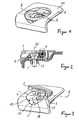
- the device according to the invention for lashing luggage parts in motor vehicles consists essentially of a base 1, a fastening screw 2, an eyelet 3, a first connecting part 4 and a second O-shaped connecting part 5.
- the bow-shaped eyelet 3, around which an unillustrated belt or belt of the luggage part is wrapped around, is mounted about a horizontally extending pivot axis 6 pivotally to the second connecting part 5 and the base 1.
- the first connecting part 4 is formed as a bolt which extends through mutually aligned hinge openings 7 and 8 of the eyelet 3 and the second connecting part 5.
- a hollow cylindrical locking element 9 is arranged, by means of which the eyelet 3 can be set in a rest position in which the eyelet 3 is recessed in recess 10 of the base 1, and other upright holding positions.
- the depth of the recess 10 is selected such that the eyelet 3 is flush in the rest position to a top surface 11 of the base 1.
- a nose-shaped bulge 12 of the recess 10 allows detecting the eyelet 3 in the rest position.
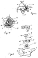
- the locking element 9 is formed as a plastic part and has a reinforcing nose 13, with which it bears by clamping on an inner side of the eyelet 3. Through this frictional connection, the adjusting element 9 rotates together with the eyelet 3 from the rest position to a predetermined holding position and vice versa.
- the locking element 9 allows the adjustment of the eyelet 3 in preferably three adjustment positions (holding / rest position).
- the locking element 9 has on its lateral surface 16 on a plurality of axial recesses 14, which cooperate detent in a corresponding holding position with a retaining lug 15 of the second connecting part 5.
- the eyelet 3 can be pivoted stepwise into predetermined holding positions.
- the outer diameter of the locking element 9 is preferably selected such that a pivoting of the eyelet 3 is given with little manual effort.
- the eyelet 3 can be spent in steps in a predetermined holding position, wherein an inclination angle ⁇ can be inclined or upright in an angular range of 0 to 90 °.
- the locking element 9 has a bore so that it is supported with clearance on the bolt 4.
- the second connecting part 5 is o-ring-shaped and has a receptacle 17, in which a head 18 of the fastening screw 2 with flush conclusion of an end face 19 of the same with an upper side 20 of the second connecting part 5 closes.
- the fastening screw 2 allows a fastening of the second connecting part 5 and the base 1 to a body part, not shown, of the motor vehicle.
- the fastening screw 2 after insertion into a bore 21 of the second connecting part 5 and in a bottom hole 22 socket 1 at the free end of the shaft thereof with a nut 23 is provided.
- a fixing plate 25 is preferably provided between the second connecting part 5 and a bottom 24 of the base 1.
- the curved mounting plate 25 ensures a uniform rotational movement of the eyelet 3 and the locking element 9 about the pivot axis 6 and prevents contamination of the rotational surfaces of the second connecting part fifth
- the bore 21 of the second connecting part 5 is selected such that the second connecting part 5 is rotatable about the longitudinal axis of the fastening screw 2.
- the longitudinal axis of the fastening screw 2 forms a vertical axis of rotation 26, which is perpendicular to the pivot axis 6.
- the eyelet 3 can thus be rotated in a horizontal plane, so that when erecting the eyelet 3 the same can be brought into an optimal attack position to the effective direction of the belt of the luggage part. After exercising an outgoing from the belt holding force, the position of the eyelet 3 can be further changed both about the axis of rotation 26 and about the pivot axis 6, so that a spatial tracking of the eyelet 3 is ensured.
- the eyelet 3 and the second connection part 5 are preferably made of a zinc material.
- the first connection part 4 is preferably made of a steel material.
- the locking element 9 is preferably formed as a plastic injection molded part (POM).
Landscapes
- Engineering & Computer Science (AREA)
- Mechanical Engineering (AREA)
- Transportation (AREA)
- Vehicle Step Arrangements And Article Storage (AREA)
- Basic Packing Technique (AREA)
- Winding Of Webs (AREA)
- Connection Of Motors, Electrical Generators, Mechanical Devices, And The Like (AREA)
Claims (5)
- Dispositif d'amarrage de bagages dans un véhicule automobile, avec un socle (1) qui est relié fixement à une pièce de la carrosserie du véhicule automobile, avec un oeillet (3), qui est monté au socle, en pivotement autour d'un axe de pivotement (6), au moyen d'un élément de liaison (4), que l'oeillet (3) est monté en rotation autour d'un axe de rotation (26) s'étendant perpendiculairement à l'axe de pivotement (6), au moyen d'un deuxième autre élément de liaison (5), que l'oeillet (3) est monté en pouvant pivoter, par rapport à l'élément de liaison (5), autour de l'axe de pivotement (6), que le deuxième élément de liaison (5) présente un alésage (21) dans lequel est agencé, avec jeu, une tête d'une vis de fixation (2) pour la fixation du socle (1) et du deuxième élément de liaison (5) à la pièce de la carrosserie, le deuxième élément de liaison (5) pouvant tourner autour de l'axe longitudinal de la vis de fixation (2) qui forme l'axe de rotation (26),
caractérisé en ce que
le premier élément de liaison (4) est formé par un boulon (4) qui passe à travers des ouvertures d'articulation (7, 8) de l'oeillet (3) et du deuxième élément de liaison (5), en alignement l'une par rapport à l'autre, et en ce qu'à l'oeillet (3) est associé un élément de blocage (9) en forme de cylindre creux qui est monté sur le boulon (4) et qui présente, sur la surface extérieur (16), plusieurs cavités axiales (14) qui coopèrent par enclenchement avec un mentonnet de retenue (15) du deuxième élément de liaison (5), de sorte que l'oeillet (3) peut être fixé pas-à-pas dans une position d'arrêt prédéterminée. - Dispositif selon la revendication 1, caractérisé en ce que le deuxième élément de liaison (5) s'étend en nappe dans un évidement (10) du socle (1).
- Dispositif selon revendication 1 ou 2, caractérisé en ce que le deuxième élément de liaison (5) est conçu en forme de joint torique.
- Dispositif selon l'une des revendications 1 à 3, caractérisé en ce que l'élément de blocage (9) est maintenu en coincement sur l'oeillet (3), avec un taquet de renforcement (13).
- Dispositif selon l'une des revendications 1 à 4, caractérisé en ce que l'élément de blocage (9) est réalisé en tant que pièce en matière synthétique.
Applications Claiming Priority (2)
| Application Number | Priority Date | Filing Date | Title |
|---|---|---|---|
| DE202004003237U | 2004-02-27 | ||
| DE202004003237U DE202004003237U1 (de) | 2004-02-27 | 2004-02-27 | Vorrichtung zum Verzurren von Gepäckteilen im Kraftfahrzeug |
Publications (2)
| Publication Number | Publication Date |
|---|---|
| EP1568540A1 EP1568540A1 (fr) | 2005-08-31 |
| EP1568540B1 true EP1568540B1 (fr) | 2007-08-15 |
Family
ID=32309217
Family Applications (1)
| Application Number | Title | Priority Date | Filing Date |
|---|---|---|---|
| EP04028456A Not-in-force EP1568540B1 (fr) | 2004-02-27 | 2004-12-01 | Dispositif d'amarrage de Bagages dans un véhicule |
Country Status (3)
| Country | Link |
|---|---|
| EP (1) | EP1568540B1 (fr) |
| AT (1) | ATE370028T1 (fr) |
| DE (2) | DE202004003237U1 (fr) |
Families Citing this family (7)
| Publication number | Priority date | Publication date | Assignee | Title |
|---|---|---|---|---|
| DE102005015348B4 (de) * | 2005-04-01 | 2007-09-27 | Dümer, Peter | Haltevorrichtung für Teile eines Kraftfahrzeugs |
| DE202005012945U1 (de) | 2005-08-15 | 2005-10-27 | Ymos-Hdo Gmbh | Vorrichtung zum Verankern von Ladegütern im Kraftfahrzeug |
| ATE551228T1 (de) | 2009-08-31 | 2012-04-15 | Ymos Gmbh | Verzurrvorrichtung |
| CN104290669B (zh) * | 2014-10-29 | 2016-08-24 | 安徽江淮汽车股份有限公司 | 一种行李箱物品固定吊钩总成 |
| CN105253065A (zh) * | 2015-11-12 | 2016-01-20 | 张家港孚冈汽车部件有限公司 | 汽车行李箱货物捆绑器 |
| DE102017117758B4 (de) * | 2017-08-04 | 2022-07-21 | TS Gesellschaft für Transport- und Sicherungssysteme mbH | Ösen-Einsatz, Wand mit eingebautem Ösen-Einsatz sowie Verfahren zum Montieren des Ösen-Einsatzes |
| DE102018213827A1 (de) * | 2018-08-16 | 2020-02-20 | Rud Ketten Rieger & Dietz Gmbh U. Co. Kg | Anschlagvorrichtung mit Schnappmechanismus |
Family Cites Families (3)
| Publication number | Priority date | Publication date | Assignee | Title |
|---|---|---|---|---|
| DE10005717A1 (de) * | 2000-02-09 | 2001-08-16 | Volkswagen Ag | Verzurreinrichtung, insbesondere für einen Kraftfahrzeug-Laderaum |
| DE10228046B4 (de) * | 2002-06-24 | 2010-08-26 | Volkswagen Ag | Halterungsöse für ein Verzurrmittel zum Sichern von Ladegut in einem Fahrzeug |
| EP1413503B1 (fr) * | 2002-10-21 | 2007-05-30 | Frank James Hardie | Ancrage de sécurité avec anneau pivotant |
-
2004
- 2004-02-27 DE DE202004003237U patent/DE202004003237U1/de not_active Expired - Lifetime
- 2004-12-01 EP EP04028456A patent/EP1568540B1/fr not_active Not-in-force
- 2004-12-01 DE DE502004004635T patent/DE502004004635D1/de active Active
- 2004-12-01 AT AT04028456T patent/ATE370028T1/de not_active IP Right Cessation
Also Published As
| Publication number | Publication date |
|---|---|
| ATE370028T1 (de) | 2007-09-15 |
| DE502004004635D1 (de) | 2007-09-27 |
| EP1568540A1 (fr) | 2005-08-31 |
| DE202004003237U1 (de) | 2004-05-06 |
Similar Documents
| Publication | Publication Date | Title |
|---|---|---|
| EP1688659B1 (fr) | Dispositif de joint universel entre un support d'appareil et un bras de support ou une console | |
| DE60307218T2 (de) | Neigungseinstell-Einheit für Lenksäulen | |
| DE3325295C2 (fr) | ||
| DE2630370C3 (de) | Einstellbares Lenkrad | |
| DE10008277B4 (de) | Schließvorrichtung | |
| DE10194785B3 (de) | Klappbare Armstütze für ein Kraftfahrzeug | |
| DE2945950A1 (de) | Spannkrallenbefestigung zum anbringen eines dachgepaecktraegers an einem kraftwagen | |
| EP1568540B1 (fr) | Dispositif d'amarrage de Bagages dans un véhicule | |
| DE60304438T2 (de) | Halterahmen für elektromotorisch angetriebene Radfahrzeuge | |
| DE2847990B2 (de) | Einstelleinrichtung für Scheinwerfer von Kraftfahrzeugen | |
| DE3621042A1 (de) | Kippbare lenksaeule fuer ein kraftfahrzeug | |
| DE19812490A1 (de) | Einrichtung zur lösbaren Befestigung eines Sitzes, insbesondere Fahrzeugsitzes, an einer längsverlaufenden Schiene | |
| DE19854985A1 (de) | Armlehne mit verstellbarer Tischplatte | |
| DE19603817A1 (de) | Vorrichtung zur Verriegelung eines Containers an einem Fahrzeugchassis | |
| DE4119802C1 (fr) | ||
| DE8533057U1 (de) | Fahrzeugaußenspiegel | |
| DE10053501A1 (de) | Tretroller, Skateboard oder ähnliches Fahrzeug | |
| DE3808083C1 (fr) | ||
| DE19915315C2 (de) | Neigungsverstellvorrichtung für eine Fondsitzlehne | |
| EP0928250B1 (fr) | Dispositif de rotation | |
| EP0825057B1 (fr) | Dispositif pour le support rotatif d'objets autour d'un axe de rotation | |
| DE19716670A1 (de) | Kupplungsvorrichtung für einen vorzugsweise rückseitigen Anschluß eines Lastenträgers an ein Fahrzeug, insbesondere an einen PKW | |
| DE3829929A1 (de) | Hoehenverstellvorrichtung fuer einen beschlag eines sicherheitsgurt-rueckhaltesystems in kraftfahrzeugen | |
| EP0221255A2 (fr) | Rétroviseur pour véhicule | |
| DE4333695C1 (de) | Vorrichtung zum Einstellen eines ersten Bauteils relativ zu einem zweiten Bauteil |
Legal Events
| Date | Code | Title | Description |
|---|---|---|---|
| PUAI | Public reference made under article 153(3) epc to a published international application that has entered the european phase |
Free format text: ORIGINAL CODE: 0009012 |
|
| AK | Designated contracting states |
Kind code of ref document: A1 Designated state(s): AT BE BG CH CY CZ DE DK EE ES FI FR GB GR HU IE IS IT LI LT LU MC NL PL PT RO SE SI SK TR |
|
| AX | Request for extension of the european patent |
Extension state: AL BA HR LV MK YU |
|
| 17P | Request for examination filed |
Effective date: 20060210 |
|
| AKX | Designation fees paid |
Designated state(s): AT BE BG CH CY CZ DE DK EE ES FI FR GB GR HU IE IS IT LI LT LU MC NL PL PT RO SE SI SK TR |
|
| RAP1 | Party data changed (applicant data changed or rights of an application transferred) |
Owner name: YMOS GMBH |
|
| GRAP | Despatch of communication of intention to grant a patent |
Free format text: ORIGINAL CODE: EPIDOSNIGR1 |
|
| GRAS | Grant fee paid |
Free format text: ORIGINAL CODE: EPIDOSNIGR3 |
|
| GRAA | (expected) grant |
Free format text: ORIGINAL CODE: 0009210 |
|
| AK | Designated contracting states |
Kind code of ref document: B1 Designated state(s): AT BE BG CH CY CZ DE DK EE ES FI FR GB GR HU IE IS IT LI LT LU MC NL PL PT RO SE SI SK TR |
|
| REG | Reference to a national code |
Ref country code: GB Ref legal event code: FG4D Free format text: NOT ENGLISH |
|
| REG | Reference to a national code |
Ref country code: CH Ref legal event code: EP |
|
| REG | Reference to a national code |
Ref country code: IE Ref legal event code: FG4D Free format text: LANGUAGE OF EP DOCUMENT: GERMAN |
|
| REF | Corresponds to: |
Ref document number: 502004004635 Country of ref document: DE Date of ref document: 20070927 Kind code of ref document: P |
|
| PG25 | Lapsed in a contracting state [announced via postgrant information from national office to epo] |
Ref country code: LT Free format text: LAPSE BECAUSE OF FAILURE TO SUBMIT A TRANSLATION OF THE DESCRIPTION OR TO PAY THE FEE WITHIN THE PRESCRIBED TIME-LIMIT Effective date: 20070815 Ref country code: FI Free format text: LAPSE BECAUSE OF FAILURE TO SUBMIT A TRANSLATION OF THE DESCRIPTION OR TO PAY THE FEE WITHIN THE PRESCRIBED TIME-LIMIT Effective date: 20070815 Ref country code: IS Free format text: LAPSE BECAUSE OF FAILURE TO SUBMIT A TRANSLATION OF THE DESCRIPTION OR TO PAY THE FEE WITHIN THE PRESCRIBED TIME-LIMIT Effective date: 20071215 Ref country code: ES Free format text: LAPSE BECAUSE OF FAILURE TO SUBMIT A TRANSLATION OF THE DESCRIPTION OR TO PAY THE FEE WITHIN THE PRESCRIBED TIME-LIMIT Effective date: 20071126 Ref country code: BG Free format text: LAPSE BECAUSE OF FAILURE TO SUBMIT A TRANSLATION OF THE DESCRIPTION OR TO PAY THE FEE WITHIN THE PRESCRIBED TIME-LIMIT Effective date: 20071115 Ref country code: NL Free format text: LAPSE BECAUSE OF FAILURE TO SUBMIT A TRANSLATION OF THE DESCRIPTION OR TO PAY THE FEE WITHIN THE PRESCRIBED TIME-LIMIT Effective date: 20070815 |
|
| NLV1 | Nl: lapsed or annulled due to failure to fulfill the requirements of art. 29p and 29m of the patents act | ||
| PG25 | Lapsed in a contracting state [announced via postgrant information from national office to epo] |
Ref country code: PL Free format text: LAPSE BECAUSE OF FAILURE TO SUBMIT A TRANSLATION OF THE DESCRIPTION OR TO PAY THE FEE WITHIN THE PRESCRIBED TIME-LIMIT Effective date: 20070815 |
|
| GBV | Gb: ep patent (uk) treated as always having been void in accordance with gb section 77(7)/1977 [no translation filed] |
Effective date: 20070815 |
|
| REG | Reference to a national code |
Ref country code: IE Ref legal event code: FD4D |
|
| EN | Fr: translation not filed | ||
| PG25 | Lapsed in a contracting state [announced via postgrant information from national office to epo] |
Ref country code: GR Free format text: LAPSE BECAUSE OF FAILURE TO SUBMIT A TRANSLATION OF THE DESCRIPTION OR TO PAY THE FEE WITHIN THE PRESCRIBED TIME-LIMIT Effective date: 20071116 Ref country code: DK Free format text: LAPSE BECAUSE OF FAILURE TO SUBMIT A TRANSLATION OF THE DESCRIPTION OR TO PAY THE FEE WITHIN THE PRESCRIBED TIME-LIMIT Effective date: 20070815 |
|
| PG25 | Lapsed in a contracting state [announced via postgrant information from national office to epo] |
Ref country code: GB Free format text: LAPSE BECAUSE OF FAILURE TO SUBMIT A TRANSLATION OF THE DESCRIPTION OR TO PAY THE FEE WITHIN THE PRESCRIBED TIME-LIMIT Effective date: 20070815 Ref country code: CZ Free format text: LAPSE BECAUSE OF FAILURE TO SUBMIT A TRANSLATION OF THE DESCRIPTION OR TO PAY THE FEE WITHIN THE PRESCRIBED TIME-LIMIT Effective date: 20070815 Ref country code: IE Free format text: LAPSE BECAUSE OF FAILURE TO SUBMIT A TRANSLATION OF THE DESCRIPTION OR TO PAY THE FEE WITHIN THE PRESCRIBED TIME-LIMIT Effective date: 20070815 Ref country code: SK Free format text: LAPSE BECAUSE OF FAILURE TO SUBMIT A TRANSLATION OF THE DESCRIPTION OR TO PAY THE FEE WITHIN THE PRESCRIBED TIME-LIMIT Effective date: 20070815 Ref country code: PT Free format text: LAPSE BECAUSE OF FAILURE TO SUBMIT A TRANSLATION OF THE DESCRIPTION OR TO PAY THE FEE WITHIN THE PRESCRIBED TIME-LIMIT Effective date: 20080115 |
|
| PLBE | No opposition filed within time limit |
Free format text: ORIGINAL CODE: 0009261 |
|
| STAA | Information on the status of an ep patent application or granted ep patent |
Free format text: STATUS: NO OPPOSITION FILED WITHIN TIME LIMIT |
|
| BERE | Be: lapsed |
Owner name: YMOS G.M.B.H. Effective date: 20071231 |
|
| PG25 | Lapsed in a contracting state [announced via postgrant information from national office to epo] |
Ref country code: RO Free format text: LAPSE BECAUSE OF FAILURE TO SUBMIT A TRANSLATION OF THE DESCRIPTION OR TO PAY THE FEE WITHIN THE PRESCRIBED TIME-LIMIT Effective date: 20070815 Ref country code: SE Free format text: LAPSE BECAUSE OF FAILURE TO SUBMIT A TRANSLATION OF THE DESCRIPTION OR TO PAY THE FEE WITHIN THE PRESCRIBED TIME-LIMIT Effective date: 20071115 |
|
| 26N | No opposition filed |
Effective date: 20080516 |
|
| PG25 | Lapsed in a contracting state [announced via postgrant information from national office to epo] |
Ref country code: MC Free format text: LAPSE BECAUSE OF NON-PAYMENT OF DUE FEES Effective date: 20071231 |
|
| PG25 | Lapsed in a contracting state [announced via postgrant information from national office to epo] |
Ref country code: BE Free format text: LAPSE BECAUSE OF NON-PAYMENT OF DUE FEES Effective date: 20071231 |
|
| PG25 | Lapsed in a contracting state [announced via postgrant information from national office to epo] |
Ref country code: EE Free format text: LAPSE BECAUSE OF FAILURE TO SUBMIT A TRANSLATION OF THE DESCRIPTION OR TO PAY THE FEE WITHIN THE PRESCRIBED TIME-LIMIT Effective date: 20070815 |
|
| PG25 | Lapsed in a contracting state [announced via postgrant information from national office to epo] |
Ref country code: AT Free format text: LAPSE BECAUSE OF NON-PAYMENT OF DUE FEES Effective date: 20071201 |
|
| PG25 | Lapsed in a contracting state [announced via postgrant information from national office to epo] |
Ref country code: FR Free format text: LAPSE BECAUSE OF NON-PAYMENT OF DUE FEES Effective date: 20071231 |
|
| PG25 | Lapsed in a contracting state [announced via postgrant information from national office to epo] |
Ref country code: SI Free format text: LAPSE BECAUSE OF FAILURE TO SUBMIT A TRANSLATION OF THE DESCRIPTION OR TO PAY THE FEE WITHIN THE PRESCRIBED TIME-LIMIT Effective date: 20070815 |
|
| PG25 | Lapsed in a contracting state [announced via postgrant information from national office to epo] |
Ref country code: CY Free format text: LAPSE BECAUSE OF FAILURE TO SUBMIT A TRANSLATION OF THE DESCRIPTION OR TO PAY THE FEE WITHIN THE PRESCRIBED TIME-LIMIT Effective date: 20070815 |
|
| REG | Reference to a national code |
Ref country code: CH Ref legal event code: PL |
|
| PG25 | Lapsed in a contracting state [announced via postgrant information from national office to epo] |
Ref country code: LU Free format text: LAPSE BECAUSE OF NON-PAYMENT OF DUE FEES Effective date: 20071201 |
|
| PG25 | Lapsed in a contracting state [announced via postgrant information from national office to epo] |
Ref country code: HU Free format text: LAPSE BECAUSE OF FAILURE TO SUBMIT A TRANSLATION OF THE DESCRIPTION OR TO PAY THE FEE WITHIN THE PRESCRIBED TIME-LIMIT Effective date: 20080216 Ref country code: TR Free format text: LAPSE BECAUSE OF FAILURE TO SUBMIT A TRANSLATION OF THE DESCRIPTION OR TO PAY THE FEE WITHIN THE PRESCRIBED TIME-LIMIT Effective date: 20070815 |
|
| PG25 | Lapsed in a contracting state [announced via postgrant information from national office to epo] |
Ref country code: LI Free format text: LAPSE BECAUSE OF NON-PAYMENT OF DUE FEES Effective date: 20081231 Ref country code: CH Free format text: LAPSE BECAUSE OF NON-PAYMENT OF DUE FEES Effective date: 20081231 |
|
| PG25 | Lapsed in a contracting state [announced via postgrant information from national office to epo] |
Ref country code: IT Free format text: LAPSE BECAUSE OF NON-PAYMENT OF DUE FEES Effective date: 20071231 |
|
| REG | Reference to a national code |
Ref country code: DE Ref legal event code: R082 Ref document number: 502004004635 Country of ref document: DE Representative=s name: PATENTANWAELTE FIEDLER, OSTERMANN & SCHNEIDER, DE Effective date: 20140220 Ref country code: DE Ref legal event code: R081 Ref document number: 502004004635 Country of ref document: DE Owner name: BRS YMOS GMBH, DE Free format text: FORMER OWNER: YMOS GMBH, 55743 IDAR-OBERSTEIN, DE Effective date: 20140220 |
|
| PGFP | Annual fee paid to national office [announced via postgrant information from national office to epo] |
Ref country code: DE Payment date: 20170224 Year of fee payment: 13 |
|
| REG | Reference to a national code |
Ref country code: DE Ref legal event code: R119 Ref document number: 502004004635 Country of ref document: DE |
|
| PG25 | Lapsed in a contracting state [announced via postgrant information from national office to epo] |
Ref country code: DE Free format text: LAPSE BECAUSE OF NON-PAYMENT OF DUE FEES Effective date: 20180703 |