EP1688659B1 - Universal joint device between an apparatus holder and a supporting arm or a console - Google Patents
Universal joint device between an apparatus holder and a supporting arm or a console Download PDFInfo
- Publication number
- EP1688659B1 EP1688659B1 EP06001287A EP06001287A EP1688659B1 EP 1688659 B1 EP1688659 B1 EP 1688659B1 EP 06001287 A EP06001287 A EP 06001287A EP 06001287 A EP06001287 A EP 06001287A EP 1688659 B1 EP1688659 B1 EP 1688659B1
- Authority
- EP
- European Patent Office
- Prior art keywords
- shank
- tensioning
- ball joint
- ball
- screw
- Prior art date
- Legal status (The legal status is an assumption and is not a legal conclusion. Google has not performed a legal analysis and makes no representation as to the accuracy of the status listed.)
- Not-in-force
Links
- 230000007246 mechanism Effects 0.000 claims abstract description 15
- 230000013011 mating Effects 0.000 claims description 4
- 238000006073 displacement reaction Methods 0.000 description 2
- 239000000969 carrier Substances 0.000 description 1
- 210000000078 claw Anatomy 0.000 description 1
- 230000008878 coupling Effects 0.000 description 1
- 238000010168 coupling process Methods 0.000 description 1
- 238000005859 coupling reaction Methods 0.000 description 1
- 210000003811 finger Anatomy 0.000 description 1
- 238000010438 heat treatment Methods 0.000 description 1
- 230000004048 modification Effects 0.000 description 1
- 238000012986 modification Methods 0.000 description 1
- 210000003813 thumb Anatomy 0.000 description 1
- 230000000007 visual effect Effects 0.000 description 1
Images


Classifications
-
- F—MECHANICAL ENGINEERING; LIGHTING; HEATING; WEAPONS; BLASTING
- F16—ENGINEERING ELEMENTS AND UNITS; GENERAL MEASURES FOR PRODUCING AND MAINTAINING EFFECTIVE FUNCTIONING OF MACHINES OR INSTALLATIONS; THERMAL INSULATION IN GENERAL
- F16C—SHAFTS; FLEXIBLE SHAFTS; ELEMENTS OR CRANKSHAFT MECHANISMS; ROTARY BODIES OTHER THAN GEARING ELEMENTS; BEARINGS
- F16C11/00—Pivots; Pivotal connections
- F16C11/04—Pivotal connections
- F16C11/10—Arrangements for locking
- F16C11/103—Arrangements for locking frictionally clamped
- F16C11/106—Arrangements for locking frictionally clamped for ball joints
-
- F—MECHANICAL ENGINEERING; LIGHTING; HEATING; WEAPONS; BLASTING
- F16—ENGINEERING ELEMENTS AND UNITS; GENERAL MEASURES FOR PRODUCING AND MAINTAINING EFFECTIVE FUNCTIONING OF MACHINES OR INSTALLATIONS; THERMAL INSULATION IN GENERAL
- F16C—SHAFTS; FLEXIBLE SHAFTS; ELEMENTS OR CRANKSHAFT MECHANISMS; ROTARY BODIES OTHER THAN GEARING ELEMENTS; BEARINGS
- F16C11/00—Pivots; Pivotal connections
- F16C11/04—Pivotal connections
- F16C11/06—Ball-joints; Other joints having more than one degree of angular freedom, i.e. universal joints
- F16C11/0661—Ball-joints; Other joints having more than one degree of angular freedom, i.e. universal joints the two co-operative parts each having both convex and concave interfaces
-
- F—MECHANICAL ENGINEERING; LIGHTING; HEATING; WEAPONS; BLASTING
- F16—ENGINEERING ELEMENTS AND UNITS; GENERAL MEASURES FOR PRODUCING AND MAINTAINING EFFECTIVE FUNCTIONING OF MACHINES OR INSTALLATIONS; THERMAL INSULATION IN GENERAL
- F16M—FRAMES, CASINGS OR BEDS OF ENGINES, MACHINES OR APPARATUS, NOT SPECIFIC TO ENGINES, MACHINES OR APPARATUS PROVIDED FOR ELSEWHERE; STANDS; SUPPORTS
- F16M11/00—Stands or trestles as supports for apparatus or articles placed thereon Stands for scientific apparatus such as gravitational force meters
- F16M11/02—Heads
- F16M11/04—Means for attachment of apparatus; Means allowing adjustment of the apparatus relatively to the stand
- F16M11/06—Means for attachment of apparatus; Means allowing adjustment of the apparatus relatively to the stand allowing pivoting
- F16M11/12—Means for attachment of apparatus; Means allowing adjustment of the apparatus relatively to the stand allowing pivoting in more than one direction
- F16M11/14—Means for attachment of apparatus; Means allowing adjustment of the apparatus relatively to the stand allowing pivoting in more than one direction with ball-joint
-
- F—MECHANICAL ENGINEERING; LIGHTING; HEATING; WEAPONS; BLASTING
- F16—ENGINEERING ELEMENTS AND UNITS; GENERAL MEASURES FOR PRODUCING AND MAINTAINING EFFECTIVE FUNCTIONING OF MACHINES OR INSTALLATIONS; THERMAL INSULATION IN GENERAL
- F16M—FRAMES, CASINGS OR BEDS OF ENGINES, MACHINES OR APPARATUS, NOT SPECIFIC TO ENGINES, MACHINES OR APPARATUS PROVIDED FOR ELSEWHERE; STANDS; SUPPORTS
- F16M11/00—Stands or trestles as supports for apparatus or articles placed thereon Stands for scientific apparatus such as gravitational force meters
- F16M11/20—Undercarriages with or without wheels
- F16M11/2007—Undercarriages with or without wheels comprising means allowing pivoting adjustment
- F16M11/2035—Undercarriages with or without wheels comprising means allowing pivoting adjustment in more than one direction
- F16M11/2064—Undercarriages with or without wheels comprising means allowing pivoting adjustment in more than one direction for tilting and panning
-
- F—MECHANICAL ENGINEERING; LIGHTING; HEATING; WEAPONS; BLASTING
- F16—ENGINEERING ELEMENTS AND UNITS; GENERAL MEASURES FOR PRODUCING AND MAINTAINING EFFECTIVE FUNCTIONING OF MACHINES OR INSTALLATIONS; THERMAL INSULATION IN GENERAL
- F16M—FRAMES, CASINGS OR BEDS OF ENGINES, MACHINES OR APPARATUS, NOT SPECIFIC TO ENGINES, MACHINES OR APPARATUS PROVIDED FOR ELSEWHERE; STANDS; SUPPORTS
- F16M13/00—Other supports for positioning apparatus or articles; Means for steadying hand-held apparatus or articles
- F16M13/02—Other supports for positioning apparatus or articles; Means for steadying hand-held apparatus or articles for supporting on, or attaching to, an object, e.g. tree, gate, window-frame, cycle
- F16M13/022—Other supports for positioning apparatus or articles; Means for steadying hand-held apparatus or articles for supporting on, or attaching to, an object, e.g. tree, gate, window-frame, cycle repositionable
-
- F—MECHANICAL ENGINEERING; LIGHTING; HEATING; WEAPONS; BLASTING
- F16—ENGINEERING ELEMENTS AND UNITS; GENERAL MEASURES FOR PRODUCING AND MAINTAINING EFFECTIVE FUNCTIONING OF MACHINES OR INSTALLATIONS; THERMAL INSULATION IN GENERAL
- F16M—FRAMES, CASINGS OR BEDS OF ENGINES, MACHINES OR APPARATUS, NOT SPECIFIC TO ENGINES, MACHINES OR APPARATUS PROVIDED FOR ELSEWHERE; STANDS; SUPPORTS
- F16M2200/00—Details of stands or supports
- F16M2200/02—Locking means
- F16M2200/021—Locking means for rotational movement
- F16M2200/022—Locking means for rotational movement by friction
Landscapes
- Engineering & Computer Science (AREA)
- General Engineering & Computer Science (AREA)
- Mechanical Engineering (AREA)
- Pivots And Pivotal Connections (AREA)
- Vehicle Step Arrangements And Article Storage (AREA)
Abstract
Description
Die Erfindung betrifft eine Universalgelenkanordnung zur Verbindung eines Gerätehalters oder einer Gerätehalter-Montageplatte oder dergl. mit einem Tragarm oder einer Konsole.The invention relates to a universal joint assembly for connecting a device holder or a device holder mounting plate or the like. With a support arm or a console.
Mobile Geräte wie Kleincomputer, sogenannte PDAs (Personal Digital Assistant), Navigationsgeräte, Mobiltelefone und dergleichen werden in Kraftfahrzeugen, auf Schreibtischen oder an anderen Orten unter Verwendung von Geräteträgern benutzt, die eine Konsole oder einen Tragarm aufweisen, an der bzw. dem über einen Gelenkmechanismus ein Gerätehalter oder eine Montageplatte zu dessen Aufnahme verbunden ist, so daß das betreffende Gerät in eine für das Betrachten der visuellen Anzeige des Geräts und zum Bedienen des Geräts bequeme Position einstellen zu können.Mobile devices such as personal digital assistants (PDAs), navigation devices, cell phones, and the like are used in automobiles, desks, or other locations using equipment carriers having a console or support arm connected thereto via a linkage mechanism a device holder or a mounting plate is connected to its receptacle, so that the device in question can be set in a convenient for viewing the visual display of the device and for operating the device position.
Universalgelenke zu diesem Zweck sind sowohl in Gestalt zweier aufeinanderfolgender und rechtwinklig zueinander angeordneter Scharniergelenke als auch in Gestalt von Kugelgelenken mit einer kugelig gewölbten Pfanne und einem kugelsegmentförmigen Gelenkteil bekannt. Damit das betreffende Gerät in der gewählten Position stabil verbleibt, ist es natürlich erforderlich, den Gelenkmechanismus feststellbar zu machen oder vorzuspannen, um einen ausreichenden Reibschluß zwischen den Gelenkteilen herzustellen. Bei bekannten Kugelgelenkmechanismen wird die notwendige Klemmspannung dadurch erzeugt, daß eine Schraube von der Montageplatten- bzw. Gerätehalterseite her in den Pfannenbereich des Gelenkmechanismus eingeschraubt und im notwendigen Maße festgezogen wird. Da die Gelenkteile im wesentlichen alle aus Kunststoff bestehen, der bekanntlich einen großen Wärmedehnungskoeffizienten hat, gibt es insbesondere beim Einsatz in Fahrzeugen wegen der dort auftretenden großen Temperaturänderungen, beispielsweise beim Aufheizen der Innentemperatur eines in der Sonne stehenden Fahrzeugs im Sommer, erhebliche Probleme dahingehend, daß die Klemmspannung sich so lockert, daß der Gerätehalter seine eingestellte Position nicht mehr beibehalten kann. Das ist nicht nur ärgerlich, weil dadurch die Benutzung des Geräts erheblich beeinträchtigt wird, sondern auch dadurch, daß das erforderliche Nachspannen nur mit Hilfe eines passenden Schraubendrehers und erst nach Abnehmen mindestens des Gerätehalters, wenn nicht gar auch noch der Montageplatte, möglich ist.Universal joints for this purpose are known both in the form of two successive hinges arranged at right angles to each other and in the form of ball joints with a spherically curved cup and a spherical segment-shaped joint part. Of course, in order for the device in question to remain stable in the selected position, it is necessary to lock or pre-tension the linkage mechanism to provide sufficient frictional engagement between the linkages. In known ball joint mechanisms, the necessary clamping voltage is generated by a screw is screwed from the mounting plate or device holder side forth in the pan area of the hinge mechanism and tightened to the extent necessary. Since the joint parts are substantially all made of plastic, which is known to have a large coefficient of thermal expansion, there are especially when used in vehicles because of the large temperature changes occurring there, for example during heating the internal temperature of a vehicle standing in the sun in the summer, considerable problems in that the clamping voltage loosens so that the device holder can not maintain its set position. This is not only annoying, because it significantly affects the use of the device, but also the fact that the necessary retightening only with the help of a suitable screwdriver and after removing at least the device holder, if not even the mounting plate, is possible.
Es besteht daher das Bedürfnis, eine Anordnung zu schaffen, mit welcher das aufgezeigte Problem leicht und ohne besonderen konstruktiven Aufwand in den Griff zu bekommen ist. Das kann mit einer Universalgelenkanordnung erreicht werden.There is therefore a need to provide an arrangement with which the problem indicated can be easily and without special design effort to get a grip. This can be achieved with a universal joint arrangement.
Eine Universalgelenkanordnung nach dem Oberbegriff des Anspruchs 1 ist aus der
Die Erfindung bezweckt eine Verbesserung einer deratigen Universalgelenkanordnung im Hinblick auf die Bedürfnisse eines PDA-Halters.The invention aims at improving a deratigen universal joint assembly with respect to the needs of a PDA holder.
Diese Aufgabe wird nach der Erfindung durch die Anordnung nach Patentanspruch 1 gelöst.This object is achieved according to the invention by the arrangement according to
Einige Ausfiihrungsbeispiele der Erfindung sind in den Zeichnungen dargestellt und werden nachstehend beispielshalber beschrieben. In den Zeichnungen zeigt:
- Fig. 1
- eine Seitenansicht der Kugelgelenkanordnung,
- Fig. 2
- einen Axialschnitt durch die Kugelgelenkanordnung nach
Fig. 1 in einer zur Zeichenebene derFig. 1 um 90° gedrehten Schnittebene, - Fig. 3
- als Anwendungsbeispiel einen Geräteträger mit einer Gelenkanordnung nach der Erfindung,
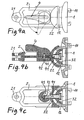
- die Fig. 4a, 4b und 4c
- eine weitere Ausführungsform einer Gelenkanornung nach der Erfindung mit einem Betätigungshebel in Ansicht und zwei um 90° zueinander gedrehten Schnittansichten,
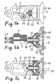
- die Fig. 5a, 5b und 5c
- eine noch weitere Ausführungsform einer Gelenkanordnung nach der Erfindung mit Federvorspannung und einem Betätigungshebel in Ansicht und zwei um 90° zueinander gedrehten Schnittansichten, und
- die Fig. 6a, 6b und 6c
- eine noch weitere Ausführungsform einer Gelenkanordnung nach der Erfindung mit einem Schiebekeil als Betätigungselement in Ansicht und zwei um 90° zueinander gedrehten Schnittansichten.
- Fig. 1
- a side view of the ball joint assembly,
- Fig. 2
- an axial section through the ball joint assembly according to
Fig. 1 in a to the plane of theFig. 1 cutting plane rotated by 90 °, - Fig. 3
- as an application example a device carrier with a joint arrangement according to the invention,
- Figs. 4a, 4b and 4c
- a further embodiment of a Gelenkanornung according to the invention with an actuating lever in view and two rotated by 90 ° to each other sectional views,
- Figs. 5a, 5b and 5c
- a still further embodiment of a hinge assembly according to the invention with spring bias and an actuating lever in view and two rotated by 90 ° to each other in cross-sectional views, and
- FIGS. 6a, 6b and 6c
- a still further embodiment of a hinge assembly according to the invention with a sliding wedge as an actuating element in view and two rotated by 90 ° to each other in cross-sectional views.
Die
Wie
Der Gelenkspannmechanismus 3 weist einen in der Kugelsegmentpfanne 22 vorspringend angeordneten Hohlzapfen 31, einen auf dessen freies Ende aufgesetzten kugelsegmentförmigen Spannkörper 32, eine vom Spannkörper 32 durch den Hohlzapfen 31 hindurchverlaufende Schraube 33 mit in einer entsprechenden Aussparung des Spannkörpers 32 drehfest sitzendem Schraubenkopf 34, eine hinterhalb der Kugelsegmentpfanne 22 auf der Schraube 33 sitzende Mutter 35 mit einem diese Mutter drehfest aufnehmenden Stellrad 36 auf. Wie
Das kugelschalenförmige Kugelgelenkteil 12 ist also, wie man sieht, zwischen der Pfanne 22 und dem Spannkörper 32 aufgenommen und zwischen diesen einspannbar. Das Kugelgelenkelement 12 hat, wie aus
Durch Drehen des am Umfang vorzugsweise gerändelten bzw. profilierten Stellrads 36 kann die Kugelgelenkanordnung jederzeit bei auf der Montageplatte 1 verrasteten Gerätehalter ohne jegliches Werkzeug gespannt, nachgespannt oder zum Verstellen gelockert werden.By turning the preferably knurled on the circumference or profiled
Wie man insbesondere aus
Als konkretes Anwendungsbeispiel ist in
Abweichend vom dargestellten Ausführungsbeispiel nach den
Weiter kann abweichend vom dargestellten Ausführungsbeispiel nach den
Nach einer weiteren, nicht dargestellten Abwandlung des in den
Nunmehr wird auf die in den weiteren Zeichnungsfiguren dargestellten Ausführungsbeispiele Bezug genommen.Reference will now be made to the embodiments illustrated in the further drawing figures.
Die
Bei dieser Ausführungsform bewirkt das Schwenken des Schwenkhebels zwischen seiner in den
Bei dem Ausführungsbeispiel nach den
Bei der in den
In den Zeichnungen ist die Anordnung in der Spannstellung dargestellt, in welcher ein etwas verdickter Kopf 64 des Schiebekeils 6 am Schwenkarm 2 anschlägt. Wird aus dieser Spannstellung der Schiebekeil 6, bezogen auf die Darstellung in
Claims (10)
- Universal joint arrangement between the end member (2) of an apparatus carrier and an apparatus holder mounting plate (1) or an apparatus holder, wherein a ball joint element (22), which is arranged on the end member (2), interacts with a ball joint element (12), which is arranged on the apparatus holder mounting plate or on the apparatus holder, and the two ball joint elements (12, 22) can be tensioned together with a frictional fit by means of a joint tensioning mechanism (3),
the joint tensioning mechanism (3) having a tensioning body (32), which is arranged on the mounting plate side or apparatus holder side, for tensioning the mounting plate-side or apparatus holder-side ball joint element (12), which is embodied as a ball shell, against the end member-side ball joint element (22), which is embodied as a ball socket, and a shank (33; 41; 51; 61), which passes from the tensioning body (32) through both ball joint elements (12, 22) to the end member (2), and also an actuator (36; 4; 5; 6) which is arranged behind the end member-side ball joint element (22) and interacts with the shank in order to generate an axial relative movement between itself and the tensioning body (32) for the purpose of the tensioning-together or detensioning of the ball joint elements (12, 22) by the tensioning body (32),
and the mounting plate-side or apparatus holder-side ball joint element (12), which is embodied as a ball shell, having a large central opening (13) through which the shank (33; 41; 51; 61) passes and the play of which determines the pivoting range of this ball joint element (12),
characterized in that the ball joint element (22), which is embodied as a ball socket, has an axially protruding hollow journal (31) which guides the shank and on the free end of which the tensioning body (32) is guided in an axially movable manner. - Universal joint arrangement according to claim 1, wherein the joint tensioning mechanism (3) has a screw-nut pairing of which one element, the screw or the nut, is connected in a rotationally fixed manner to the tensioning body (32) and the respective other element, the nut or the screw, is connected in a rotationally fixed manner to a finger-actuatable adjusting wheel (36) forming the actuator, the screw (33) forming in each case the aforementioned shank.
- Universal joint arrangement according to claim 2, wherein the screw (33, 34) is connected in a rotationally fixed manner to the tensioning body (32) and the adjusting wheel (36) is connected in a rotationally fixed manner to the nut (35) which sits, behind the end member-side ball joint element (22), on the screw bolt (33).
- Universal joint arrangement according to claim 3, wherein the screw (33, 34) has a screw head (34) which is received in the tensioning body (32) in a form-fitting, rotationally fixed manner.
- Universal joint arrangement according to claim 1, wherein the shank (41) is connected, by its end remote from the tensioning body (32), to an eccentric lever (4) which can be pivoted, about a pivot axis extending transversely to the longitudinal axis of the shank, between a release position and a tensioning position.
- Universal joint arrangement according to claim 5, wherein the eccentric lever (4) is connected to the shank via a transverse pin (42), which also defines the pivot axis of the eccentric lever and penetrates the end of the shank (41), and is supported with an eccentric cam on a mating surface at the back of the ball socket (22) or a component connected thereto.
- Universal joint arrangement according to claim 1, wherein the tensioning body (32) is pretensioned into its tensioning position by means of spring pretensioning acting on the shank (51) and the actuator has a rest position corresponding to the tensioning position of the tensioning body (32) and, when moving out of the rest position into a working position corresponding to the release position of the tensioning body (32), acts, counter to the spring pretensioning, on the end of the shank that is remote from the tensioning body (32).
- Universal joint arrangement according to claim 7, wherein the spring pretensioning is generated by a plate spring set (53) which is arranged concentrically on the shank (51) and penetrated by the shank and is supported, on the one hand, on the back of the ball socket (22) and, on the other hand, on a stop element (54) connected to the free shank end.
- Universal joint arrangement according to claim 7 or 8, wherein the actuator is a pivot lever (5) which can be pivoted about a pivot axis (52), which extends transversely to the shank longitudinal axis and is laterally offset therefrom, and interacts with the end face of the shank (51) via a lever element in such a way that the pivot lever assumes an unstable or a stable position in its working position corresponding to the release position of the tensioning body (32).
- Universal joint arrangement according to claim 1, wherein the actuator is a sliding wedge (6) which can be displaced transversely to the shank (61, 62) between an end position corresponding to the tensioning position of the tensioning body (32) and an end position corresponding to the release position of the tensioning body and interacts with a mating surface formed on the shank or a mating surface formed on the ball socket (22) in the manner of a wedge gear.
Priority Applications (1)
| Application Number | Priority Date | Filing Date | Title |
|---|---|---|---|
| US11/389,611 US7241069B2 (en) | 2005-02-07 | 2006-03-24 | Universal joint arrangement between an apparatus holder and a support arm or a console |
Applications Claiming Priority (1)
| Application Number | Priority Date | Filing Date | Title |
|---|---|---|---|
| DE200520001986 DE202005001986U1 (en) | 2005-02-07 | 2005-02-07 | Universal joint arrangement between a device holder and a support arm or a console |
Publications (3)
| Publication Number | Publication Date |
|---|---|
| EP1688659A2 EP1688659A2 (en) | 2006-08-09 |
| EP1688659A3 EP1688659A3 (en) | 2006-11-22 |
| EP1688659B1 true EP1688659B1 (en) | 2009-12-16 |
Family
ID=34442769
Family Applications (1)
| Application Number | Title | Priority Date | Filing Date |
|---|---|---|---|
| EP06001287A Not-in-force EP1688659B1 (en) | 2005-02-07 | 2006-01-21 | Universal joint device between an apparatus holder and a supporting arm or a console |
Country Status (4)
| Country | Link |
|---|---|
| US (1) | US20060175501A1 (en) |
| EP (1) | EP1688659B1 (en) |
| AT (1) | ATE452313T1 (en) |
| DE (2) | DE202005001986U1 (en) |
Cited By (3)
| Publication number | Priority date | Publication date | Assignee | Title |
|---|---|---|---|---|
| CN102518918A (en) * | 2011-12-27 | 2012-06-27 | 天津大学 | Adjustment support for industrial video camera |
| DE202013007384U1 (en) | 2012-08-29 | 2013-09-12 | Harald Richter | Equipment carrier console for hand-held bicycle-mounted cell phones and similar devices |
| DE102013014921B4 (en) | 2013-09-11 | 2020-04-23 | Harald Richter | Device holder with suction foot and swivel arm for mobile phones |
Families Citing this family (17)
| Publication number | Priority date | Publication date | Assignee | Title |
|---|---|---|---|---|
| US7028961B1 (en) | 2003-05-30 | 2006-04-18 | Csav, Inc. | Self-balancing adjustable flat panel mounting system |
| US7380760B2 (en) * | 2003-05-30 | 2008-06-03 | Csav, Inc. | Self-balancing adjustable mounting system with friction adjustment |
| US20070049128A1 (en) * | 2005-08-30 | 2007-03-01 | Paul Brassard | Mounting structure |
| DE202005021680U1 (en) * | 2005-09-09 | 2009-03-19 | Bury Sp.Z.O.O | navigation device |
| US20080190978A1 (en) * | 2007-02-14 | 2008-08-14 | Paul Brassard | Mounting apparatus |
| US8632042B2 (en) * | 2007-06-29 | 2014-01-21 | Draeger Medical Systems, Inc. | Tilt and swivel mounting for monitors and other devices |
| DE102007060543B3 (en) * | 2007-12-13 | 2008-10-02 | Bühler, Martin | Table, for standing customers e.g. in a bistro, has a rotating table top and a swivel joint to give an upright support and a horizontal table top when on sloping ground |
| US20090294608A1 (en) * | 2008-05-30 | 2009-12-03 | Paul Brassard | Mounting Structure |
| FR2941280B1 (en) * | 2009-01-20 | 2013-07-19 | Airbus France | ATTACHMENT DEVICE FOR FLEXIBLE HYDRAULIC PIPES |
| CN103062589A (en) * | 2011-10-21 | 2013-04-24 | 鸿富锦精密工业(深圳)有限公司 | Supporting device |
| DE102013005766A1 (en) * | 2012-10-26 | 2014-05-15 | Tormaxx Gmbh | Support structure of support assembly for e.g. camera, has flexible hinge system including connecting link which is interchangeably connected with upper and lower bracket elements, and camera holder arranged in upper bracket element |
| EP3098463B1 (en) * | 2015-05-26 | 2018-03-14 | Airbus Operations GmbH | Rotary joint, framework construction kit and method for manufacturing a rotary joint |
| EP3135833B1 (en) * | 2015-08-27 | 2019-05-08 | Airbus Operations GmbH | Rotary joint, framework construction kit, framework with rotary joints and method for manufacturing a rotary joint |
| KR20190041065A (en) | 2017-10-12 | 2019-04-22 | 에이치피프린팅코리아 유한회사 | Hinge apparatus |
| AU2019202833B2 (en) * | 2018-04-24 | 2024-04-11 | David Robertson | A roll-over protection apparatus |
| CN112682640B (en) * | 2020-12-21 | 2022-08-19 | 内蒙古师范大学 | Stable sliding mechanism for digital media art design shooting device |
| CN215003173U (en) * | 2021-01-06 | 2021-12-03 | 叶小惠 | Universal supporting mechanism |
Family Cites Families (11)
| Publication number | Priority date | Publication date | Assignee | Title |
|---|---|---|---|---|
| US86173A (en) * | 1869-01-26 | Improved baiiit-and-socket joint | ||
| GB155084A (en) * | 1919-10-27 | 1920-12-16 | Edward Moulds | An improved adjustable vice |
| US1446164A (en) * | 1920-04-01 | 1923-02-20 | D Eyraud Louis | Universal mounting device |
| US1909526A (en) * | 1932-03-23 | 1933-05-16 | Robert N Falge | Rear view mirror holder |
| US2126389A (en) * | 1936-10-19 | 1938-08-09 | Thompson Prod Inc | Ball joint |
| US3477678A (en) * | 1966-12-01 | 1969-11-11 | William M Icke | Universal vehicle sun visor mount |
| US4088129A (en) * | 1976-11-15 | 1978-05-09 | Digiulio Mario | Appliance for foot orthosis |
| SE420012B (en) * | 1978-07-13 | 1981-09-07 | Gunnar M T Kjellstrand | COUPLING TYPE CONNECTION |
| GB2096234B (en) | 1981-04-03 | 1985-02-20 | Mouldmaking Design Centre Ltd | Swivel mounting |
| US4957359A (en) * | 1989-04-19 | 1990-09-18 | Navistar International Transportation Corp. | Spring biased mirror assembly with electromagnetic release means |
| US6688798B2 (en) * | 2001-02-27 | 2004-02-10 | Incumed, Inc. | Adjustable locking mount and methods of use |
-
2005
- 2005-02-07 DE DE200520001986 patent/DE202005001986U1/en not_active Expired - Lifetime
- 2005-05-19 US US11/133,065 patent/US20060175501A1/en not_active Abandoned
-
2006
- 2006-01-21 EP EP06001287A patent/EP1688659B1/en not_active Not-in-force
- 2006-01-21 DE DE502006005634T patent/DE502006005634D1/en active Active
- 2006-01-21 AT AT06001287T patent/ATE452313T1/en active
Cited By (5)
| Publication number | Priority date | Publication date | Assignee | Title |
|---|---|---|---|---|
| CN102518918A (en) * | 2011-12-27 | 2012-06-27 | 天津大学 | Adjustment support for industrial video camera |
| DE202013007384U1 (en) | 2012-08-29 | 2013-09-12 | Harald Richter | Equipment carrier console for hand-held bicycle-mounted cell phones and similar devices |
| DE102013013703A1 (en) | 2012-08-29 | 2014-03-06 | Harald Richter | Equipment carrier console for hand-held bicycle-mounted cell phones and similar devices |
| DE102013013703B4 (en) * | 2012-08-29 | 2017-05-04 | Harald Richter | Equipment carrier console for hand-held bicycle-mounted cell phones and similar devices |
| DE102013014921B4 (en) | 2013-09-11 | 2020-04-23 | Harald Richter | Device holder with suction foot and swivel arm for mobile phones |
Also Published As
| Publication number | Publication date |
|---|---|
| US20060175501A1 (en) | 2006-08-10 |
| EP1688659A2 (en) | 2006-08-09 |
| DE202005001986U1 (en) | 2005-04-14 |
| DE502006005634D1 (en) | 2010-01-28 |
| ATE452313T1 (en) | 2010-01-15 |
| EP1688659A3 (en) | 2006-11-22 |
Similar Documents
| Publication | Publication Date | Title |
|---|---|---|
| EP1688659B1 (en) | Universal joint device between an apparatus holder and a supporting arm or a console | |
| EP1772316B1 (en) | Apparatus holder with suction cup and split column | |
| EP1429708B1 (en) | Fastening block for mounting objects on a profiled rail | |
| DE69724888T2 (en) | Shoe binding device for a gliding board | |
| WO1996022136A1 (en) | Binding for a sporting good | |
| EP0225609B1 (en) | Hinge | |
| DE3804199C2 (en) | ||
| EP1617026A2 (en) | Door hinge for motor vehicles | |
| WO1999020487A1 (en) | Holder for a mobile telephone | |
| WO2001002223A1 (en) | Wiper arm | |
| DE202009016669U1 (en) | Furniture, furniture part and device for connecting a front component of a furniture part | |
| EP1568540B1 (en) | Apparatus for fixation of baggage in a vehicle | |
| EP2197692B1 (en) | Pair of compasses having a joint with a locking device | |
| DE19646490A1 (en) | Adjustable swivel latch for door openers | |
| DE202006000945U1 (en) | Ball-and socket joint for attaching mounting plate for e.g. PC to support arm comprises socket attached to arm and two hollow, concentric balls attached to plate bolt, joint being locked in position by bolt operated by thumb wheel | |
| EP1932719B1 (en) | Holding device for packing rods | |
| DE102004048879B4 (en) | Guide system for sliding door has guide rail and roller carriage with first guide roller supported on rigid web through eccentric bolt to accommodate curved sections | |
| WO2005049272A1 (en) | Hand sanding tool | |
| DE19915054C2 (en) | Adjustment device | |
| DE102017213423B4 (en) | Coupling device for a load carrier and load carrier with such a coupling device | |
| EP2168809B1 (en) | Holding device for securing packing rods | |
| DE4324783C2 (en) | Wiper arm attachment for motor vehicle windshield wipers | |
| DE202007010567U1 (en) | Hochastschere | |
| AT407732B (en) | Adjustment device | |
| DE19704330C2 (en) | Furniture fitting |
Legal Events
| Date | Code | Title | Description |
|---|---|---|---|
| PUAI | Public reference made under article 153(3) epc to a published international application that has entered the european phase |
Free format text: ORIGINAL CODE: 0009012 |
|
| AK | Designated contracting states |
Kind code of ref document: A2 Designated state(s): AT BE BG CH CY CZ DE DK EE ES FI FR GB GR HU IE IS IT LI LT LU LV MC NL PL PT RO SE SI SK TR |
|
| AX | Request for extension of the european patent |
Extension state: AL BA HR MK YU |
|
| PUAL | Search report despatched |
Free format text: ORIGINAL CODE: 0009013 |
|
| AK | Designated contracting states |
Kind code of ref document: A3 Designated state(s): AT BE BG CH CY CZ DE DK EE ES FI FR GB GR HU IE IS IT LI LT LU LV MC NL PL PT RO SE SI SK TR |
|
| AX | Request for extension of the european patent |
Extension state: AL BA HR MK YU |
|
| 17P | Request for examination filed |
Effective date: 20070518 |
|
| AKX | Designation fees paid |
Designated state(s): AT BE BG CH CY CZ DE DK EE ES FI FR GB GR HU IE IS IT LI LT LU LV MC NL PL PT RO SE SI SK TR |
|
| 17Q | First examination report despatched |
Effective date: 20070711 |
|
| GRAP | Despatch of communication of intention to grant a patent |
Free format text: ORIGINAL CODE: EPIDOSNIGR1 |
|
| GRAS | Grant fee paid |
Free format text: ORIGINAL CODE: EPIDOSNIGR3 |
|
| GRAA | (expected) grant |
Free format text: ORIGINAL CODE: 0009210 |
|
| AK | Designated contracting states |
Kind code of ref document: B1 Designated state(s): AT BE BG CH CY CZ DE DK EE ES FI FR GB GR HU IE IS IT LI LT LU LV MC NL PL PT RO SE SI SK TR |
|
| REG | Reference to a national code |
Ref country code: GB Ref legal event code: FG4D Free format text: NOT ENGLISH |
|
| REG | Reference to a national code |
Ref country code: CH Ref legal event code: EP |
|
| REG | Reference to a national code |
Ref country code: IE Ref legal event code: FG4D |
|
| REF | Corresponds to: |
Ref document number: 502006005634 Country of ref document: DE Date of ref document: 20100128 Kind code of ref document: P |
|
| REG | Reference to a national code |
Ref country code: NL Ref legal event code: T3 |
|
| PG25 | Lapsed in a contracting state [announced via postgrant information from national office to epo] |
Ref country code: LT Free format text: LAPSE BECAUSE OF FAILURE TO SUBMIT A TRANSLATION OF THE DESCRIPTION OR TO PAY THE FEE WITHIN THE PRESCRIBED TIME-LIMIT Effective date: 20091216 Ref country code: SE Free format text: LAPSE BECAUSE OF FAILURE TO SUBMIT A TRANSLATION OF THE DESCRIPTION OR TO PAY THE FEE WITHIN THE PRESCRIBED TIME-LIMIT Effective date: 20091216 Ref country code: FI Free format text: LAPSE BECAUSE OF FAILURE TO SUBMIT A TRANSLATION OF THE DESCRIPTION OR TO PAY THE FEE WITHIN THE PRESCRIBED TIME-LIMIT Effective date: 20091216 |
|
| LTIE | Lt: invalidation of european patent or patent extension |
Effective date: 20091216 |
|
| PG25 | Lapsed in a contracting state [announced via postgrant information from national office to epo] |
Ref country code: SI Free format text: LAPSE BECAUSE OF FAILURE TO SUBMIT A TRANSLATION OF THE DESCRIPTION OR TO PAY THE FEE WITHIN THE PRESCRIBED TIME-LIMIT Effective date: 20091216 Ref country code: LV Free format text: LAPSE BECAUSE OF FAILURE TO SUBMIT A TRANSLATION OF THE DESCRIPTION OR TO PAY THE FEE WITHIN THE PRESCRIBED TIME-LIMIT Effective date: 20091216 Ref country code: PL Free format text: LAPSE BECAUSE OF FAILURE TO SUBMIT A TRANSLATION OF THE DESCRIPTION OR TO PAY THE FEE WITHIN THE PRESCRIBED TIME-LIMIT Effective date: 20091216 |
|
| REG | Reference to a national code |
Ref country code: IE Ref legal event code: FD4D Ref country code: GB Ref legal event code: 732E Free format text: REGISTERED BETWEEN 20100610 AND 20100616 |
|
| PG25 | Lapsed in a contracting state [announced via postgrant information from national office to epo] |
Ref country code: RO Free format text: LAPSE BECAUSE OF FAILURE TO SUBMIT A TRANSLATION OF THE DESCRIPTION OR TO PAY THE FEE WITHIN THE PRESCRIBED TIME-LIMIT Effective date: 20091216 Ref country code: ES Free format text: LAPSE BECAUSE OF FAILURE TO SUBMIT A TRANSLATION OF THE DESCRIPTION OR TO PAY THE FEE WITHIN THE PRESCRIBED TIME-LIMIT Effective date: 20100327 Ref country code: IE Free format text: LAPSE BECAUSE OF FAILURE TO SUBMIT A TRANSLATION OF THE DESCRIPTION OR TO PAY THE FEE WITHIN THE PRESCRIBED TIME-LIMIT Effective date: 20091216 Ref country code: PT Free format text: LAPSE BECAUSE OF FAILURE TO SUBMIT A TRANSLATION OF THE DESCRIPTION OR TO PAY THE FEE WITHIN THE PRESCRIBED TIME-LIMIT Effective date: 20100416 Ref country code: IS Free format text: LAPSE BECAUSE OF FAILURE TO SUBMIT A TRANSLATION OF THE DESCRIPTION OR TO PAY THE FEE WITHIN THE PRESCRIBED TIME-LIMIT Effective date: 20100416 Ref country code: EE Free format text: LAPSE BECAUSE OF FAILURE TO SUBMIT A TRANSLATION OF THE DESCRIPTION OR TO PAY THE FEE WITHIN THE PRESCRIBED TIME-LIMIT Effective date: 20091216 Ref country code: BG Free format text: LAPSE BECAUSE OF FAILURE TO SUBMIT A TRANSLATION OF THE DESCRIPTION OR TO PAY THE FEE WITHIN THE PRESCRIBED TIME-LIMIT Effective date: 20100316 |
|
| PG25 | Lapsed in a contracting state [announced via postgrant information from national office to epo] |
Ref country code: SK Free format text: LAPSE BECAUSE OF FAILURE TO SUBMIT A TRANSLATION OF THE DESCRIPTION OR TO PAY THE FEE WITHIN THE PRESCRIBED TIME-LIMIT Effective date: 20091216 Ref country code: CZ Free format text: LAPSE BECAUSE OF FAILURE TO SUBMIT A TRANSLATION OF THE DESCRIPTION OR TO PAY THE FEE WITHIN THE PRESCRIBED TIME-LIMIT Effective date: 20091216 Ref country code: MC Free format text: LAPSE BECAUSE OF NON-PAYMENT OF DUE FEES Effective date: 20100131 |
|
| PLBE | No opposition filed within time limit |
Free format text: ORIGINAL CODE: 0009261 |
|
| STAA | Information on the status of an ep patent application or granted ep patent |
Free format text: STATUS: NO OPPOSITION FILED WITHIN TIME LIMIT |
|
| PG25 | Lapsed in a contracting state [announced via postgrant information from national office to epo] |
Ref country code: GR Free format text: LAPSE BECAUSE OF FAILURE TO SUBMIT A TRANSLATION OF THE DESCRIPTION OR TO PAY THE FEE WITHIN THE PRESCRIBED TIME-LIMIT Effective date: 20100317 Ref country code: CY Free format text: LAPSE BECAUSE OF FAILURE TO SUBMIT A TRANSLATION OF THE DESCRIPTION OR TO PAY THE FEE WITHIN THE PRESCRIBED TIME-LIMIT Effective date: 20091216 |
|
| 26N | No opposition filed |
Effective date: 20100917 |
|
| PG25 | Lapsed in a contracting state [announced via postgrant information from national office to epo] |
Ref country code: DK Free format text: LAPSE BECAUSE OF FAILURE TO SUBMIT A TRANSLATION OF THE DESCRIPTION OR TO PAY THE FEE WITHIN THE PRESCRIBED TIME-LIMIT Effective date: 20091216 |
|
| PGFP | Annual fee paid to national office [announced via postgrant information from national office to epo] |
Ref country code: LU Payment date: 20110124 Year of fee payment: 6 |
|
| PG25 | Lapsed in a contracting state [announced via postgrant information from national office to epo] |
Ref country code: IT Free format text: LAPSE BECAUSE OF FAILURE TO SUBMIT A TRANSLATION OF THE DESCRIPTION OR TO PAY THE FEE WITHIN THE PRESCRIBED TIME-LIMIT Effective date: 20091216 |
|
| PGFP | Annual fee paid to national office [announced via postgrant information from national office to epo] |
Ref country code: NL Payment date: 20110119 Year of fee payment: 6 Ref country code: FR Payment date: 20110201 Year of fee payment: 6 Ref country code: CH Payment date: 20110125 Year of fee payment: 6 Ref country code: AT Payment date: 20110120 Year of fee payment: 6 |
|
| PGFP | Annual fee paid to national office [announced via postgrant information from national office to epo] |
Ref country code: BE Payment date: 20110124 Year of fee payment: 6 |
|
| PGFP | Annual fee paid to national office [announced via postgrant information from national office to epo] |
Ref country code: GB Payment date: 20110121 Year of fee payment: 6 |
|
| BERE | Be: lapsed |
Owner name: RICHTER, HARALD Effective date: 20120131 |
|
| REG | Reference to a national code |
Ref country code: NL Ref legal event code: V1 Effective date: 20120801 |
|
| REG | Reference to a national code |
Ref country code: CH Ref legal event code: PL |
|
| GBPC | Gb: european patent ceased through non-payment of renewal fee |
Effective date: 20120121 |
|
| PG25 | Lapsed in a contracting state [announced via postgrant information from national office to epo] |
Ref country code: HU Free format text: LAPSE BECAUSE OF FAILURE TO SUBMIT A TRANSLATION OF THE DESCRIPTION OR TO PAY THE FEE WITHIN THE PRESCRIBED TIME-LIMIT Effective date: 20100617 |
|
| REG | Reference to a national code |
Ref country code: FR Ref legal event code: ST Effective date: 20120928 |
|
| PG25 | Lapsed in a contracting state [announced via postgrant information from national office to epo] |
Ref country code: TR Free format text: LAPSE BECAUSE OF FAILURE TO SUBMIT A TRANSLATION OF THE DESCRIPTION OR TO PAY THE FEE WITHIN THE PRESCRIBED TIME-LIMIT Effective date: 20091216 Ref country code: GB Free format text: LAPSE BECAUSE OF NON-PAYMENT OF DUE FEES Effective date: 20120121 Ref country code: LI Free format text: LAPSE BECAUSE OF NON-PAYMENT OF DUE FEES Effective date: 20120131 Ref country code: CH Free format text: LAPSE BECAUSE OF NON-PAYMENT OF DUE FEES Effective date: 20120131 |
|
| REG | Reference to a national code |
Ref country code: AT Ref legal event code: MM01 Ref document number: 452313 Country of ref document: AT Kind code of ref document: T Effective date: 20120121 |
|
| PG25 | Lapsed in a contracting state [announced via postgrant information from national office to epo] |
Ref country code: FR Free format text: LAPSE BECAUSE OF NON-PAYMENT OF DUE FEES Effective date: 20120131 Ref country code: BE Free format text: LAPSE BECAUSE OF NON-PAYMENT OF DUE FEES Effective date: 20120131 |
|
| PG25 | Lapsed in a contracting state [announced via postgrant information from national office to epo] |
Ref country code: NL Free format text: LAPSE BECAUSE OF NON-PAYMENT OF DUE FEES Effective date: 20120801 Ref country code: AT Free format text: LAPSE BECAUSE OF NON-PAYMENT OF DUE FEES Effective date: 20120121 |
|
| PG25 | Lapsed in a contracting state [announced via postgrant information from national office to epo] |
Ref country code: LU Free format text: LAPSE BECAUSE OF NON-PAYMENT OF DUE FEES Effective date: 20120121 |
|
| REG | Reference to a national code |
Ref country code: DE Ref legal event code: R008 Ref document number: 502006005634 Country of ref document: DE Ref country code: DE Ref legal event code: R039 Ref document number: 502006005634 Country of ref document: DE |
|
| REG | Reference to a national code |
Ref country code: DE Ref legal event code: R040 Ref document number: 502006005634 Country of ref document: DE |
|
| PGFP | Annual fee paid to national office [announced via postgrant information from national office to epo] |
Ref country code: DE Payment date: 20220315 Year of fee payment: 17 |
|
| REG | Reference to a national code |
Ref country code: DE Ref legal event code: R082 Ref document number: 502006005634 Country of ref document: DE Representative=s name: FLEUCHAUS & GALLO PARTNERSCHAFT MBB PATENTANWA, DE Ref country code: DE Ref legal event code: R082 Ref document number: 502006005634 Country of ref document: DE Representative=s name: FLEUCHAUS & GALLO PARTNERSCHAFT MBB - PATENT- , DE |
|
| REG | Reference to a national code |
Ref country code: DE Ref legal event code: R119 Ref document number: 502006005634 Country of ref document: DE |
|
| PG25 | Lapsed in a contracting state [announced via postgrant information from national office to epo] |
Ref country code: DE Free format text: LAPSE BECAUSE OF NON-PAYMENT OF DUE FEES Effective date: 20230801 |