EP1686536B1 - Anwendung von Kantenverstärkung auf Basis von Bildeigenschaften - Google Patents
Anwendung von Kantenverstärkung auf Basis von Bildeigenschaften Download PDFInfo
- Publication number
- EP1686536B1 EP1686536B1 EP06250504A EP06250504A EP1686536B1 EP 1686536 B1 EP1686536 B1 EP 1686536B1 EP 06250504 A EP06250504 A EP 06250504A EP 06250504 A EP06250504 A EP 06250504A EP 1686536 B1 EP1686536 B1 EP 1686536B1
- Authority
- EP
- European Patent Office
- Prior art keywords
- image
- original image
- edge
- edge enhancement
- frequency value
- Prior art date
- Legal status (The legal status is an assumption and is not a legal conclusion. Google has not performed a legal analysis and makes no representation as to the accuracy of the status listed.)
- Ceased
Links
Images


Classifications
-
- G—PHYSICS
- G06—COMPUTING OR CALCULATING; COUNTING
- G06T—IMAGE DATA PROCESSING OR GENERATION, IN GENERAL
- G06T5/00—Image enhancement or restoration
- G06T5/73—Deblurring; Sharpening
-
- G—PHYSICS
- G06—COMPUTING OR CALCULATING; COUNTING
- G06T—IMAGE DATA PROCESSING OR GENERATION, IN GENERAL
- G06T5/00—Image enhancement or restoration
- G06T5/20—Image enhancement or restoration using local operators
-
- G—PHYSICS
- G06—COMPUTING OR CALCULATING; COUNTING
- G06T—IMAGE DATA PROCESSING OR GENERATION, IN GENERAL
- G06T5/00—Image enhancement or restoration
- G06T5/70—Denoising; Smoothing
-
- G—PHYSICS
- G06—COMPUTING OR CALCULATING; COUNTING
- G06T—IMAGE DATA PROCESSING OR GENERATION, IN GENERAL
- G06T7/00—Image analysis
- G06T7/10—Segmentation; Edge detection
- G06T7/12—Edge-based segmentation
-
- G—PHYSICS
- G06—COMPUTING OR CALCULATING; COUNTING
- G06T—IMAGE DATA PROCESSING OR GENERATION, IN GENERAL
- G06T2207/00—Indexing scheme for image analysis or image enhancement
- G06T2207/10—Image acquisition modality
- G06T2207/10016—Video; Image sequence
-
- G—PHYSICS
- G06—COMPUTING OR CALCULATING; COUNTING
- G06T—IMAGE DATA PROCESSING OR GENERATION, IN GENERAL
- G06T2207/00—Indexing scheme for image analysis or image enhancement
- G06T2207/20—Special algorithmic details
- G06T2207/20004—Adaptive image processing
- G06T2207/20012—Locally adaptive
-
- G—PHYSICS
- G06—COMPUTING OR CALCULATING; COUNTING
- G06T—IMAGE DATA PROCESSING OR GENERATION, IN GENERAL
- G06T2207/00—Indexing scheme for image analysis or image enhancement
- G06T2207/20—Special algorithmic details
- G06T2207/20021—Dividing image into blocks, subimages or windows
-
- G—PHYSICS
- G06—COMPUTING OR CALCULATING; COUNTING
- G06T—IMAGE DATA PROCESSING OR GENERATION, IN GENERAL
- G06T2207/00—Indexing scheme for image analysis or image enhancement
- G06T2207/20—Special algorithmic details
- G06T2207/20172—Image enhancement details
- G06T2207/20192—Edge enhancement; Edge preservation
Definitions
- the following disclosure relates generally to an apparatus, method, system, and computer program, capable of applying edge enhancement to an image based on the characteristics of the image.
- edge enhancement can increase image quality, such as by improving apparent sharpness of the image.
- edge enhancement may sometimes cause the image quality to decrease. For example, if the image contains a smooth portion, such as a picture, a background section, or a shaded area, the image quality may be lowered as smoothness in the smooth portion decreases. In another example, if the image contains an edge portion having high edge intensity, the image quality may be lowered as graininess or noise in the edge portion increases.
- US 2004/0120598 discloses a blur detection system which considers several different blur indicators. One of these is to determine whether or not the maximum DCT coefficient is greater than or less than 100.
- exemplary embodiments of the present invention provide image processing, method, apparatus, and computer program as defined in the appended claims and capable of applying edge enhancement to an image based on characteristics of the image.
- edge enhancement is applied to the original image. Further, when the edge detection result indicates to apply edge enhancement, the characteristics of the original image may be further analyzed to generate an analyzing result. The analyzing result may be considered when applying edge enhancement to the original image.
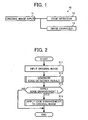
- FIG. 1 illustrates an image processing apparatus 10 according to an exemplary embodiment of the present invention.
- the image processing apparatus 10 is capable of applying edge enhancement to an image based on characteristics of the image.
- the image processing apparatus 10 includes an original image input 11, an edge detector 12, and an image enhancer 13.
- the original image input 11 inputs an original image to be processed.
- the original image input 11 may scan a printed image into image data using a scanner.
- the original image input 11 may obtain image data via a network.
- the original image input 11 may read image data from a storage device, which may be incorporated in the image processing apparatus 10.
- the input original image may be stored in a buffer of the image processing apparatus 10 further processing.
- the edge detector 12 determines whether to apply edge enhancement to the original image based on the characteristics of the original image to generate an edge detection result.
- the edge detector 12 analyzes a frequency domain of the original image to determine whether to apply edge enhancement to the original image.
- the image enhancer 13 applies various image processing to the original image to enhance the quality of the original image. For example, the image enhancer 13 applies edge enhancement to the original image if the edge detection result indicates to apply edge enhancement. In this example, the image enhancer 13 may extract an edge portion from the original image, and apply edge enhancement only to the edge portion of the original image, while leaving the unextracted portion unprocessed. If the image enhancer 13 is provided with a function of smoothing, the image enhancer 13 may apply smoothing to the unextracted portion.
- the image enhancer 13 may use a filter, which is selected based on the characteristics of the edge portion, such as the edge intensity or direction of the edge portion.
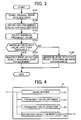
- FIG. 2 operation of applying edge enhancement to an original image, performed by the image processing apparatus 10, is explained according to an exemplary embodiment of the present invention.
- Step S11 inputs an original image to be processed.
- Step S12 generates an edge detection result based on characteristics of the original image, which indicates whether to apply edge enhancement to the original image.
- Step S13 determines whether to apply edge enhancement based on the edge detection result. If the edge detection result indicates to apply edge enhancement ("YES” in Step S13), the operation proceeds to Step S14. If the edge detection result indicates that edge enhancement is not necessary (“NO” in Step S13), the operation ends to output the original image without applying edge enhancement.
- Step S14 applies edge enhancement to the original image, such as to an edge portion of the original image.
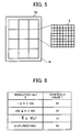
- Step S12 of generating an edge detection result is explained in more detail according to an exemplary embodiment of the present invention.
- the steps illustrated in FIG. 3 are performed by the edge detector 12 having the structure shown in FIG. 4 .
- the edge detector 12 includes an image divider 121, a frequency value obtainer 122, a frequency value analyzer 123, and a detection result generator 124.
- the image divider 121 divides an original image into a plurality of sections.
- the frequency value obtainer 122 obtains a high frequency value for at least one of the plurality of sections, by converting the original image from a spatial domain to a frequency domain.
- the frequency value analyzer 123 analyzes the high frequency value of the at least one section, which is obtained by the frequency value obtainer 122, to generate an analyzing result.
- the detection result generator 124 generates an edge detection result based on the analyzing result generated by the frequency value analyzer 123.
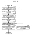
- Step S121 divides the original image into a plurality of sections. For example, if an original image D0 illustrated in FIG. 5 is input in Step S11 of FIG. 2 , the image divider 121 of FIG. 4 divides the original image D0 into a plurality of sections S, each section S having 8 pixels by 8 pixels. Further, in this example, since the original image D0 contains the number of pixels, which cannot be divided by 8, the original image D0 has at least one pixel not belonging to any one of the sections (indicated by "M" in FIG. 5 ). Alternatively, when the original image D0 contains the number of pixels, which is not a multiple of 8, the copy of a last row or column of pixels may be added until the number of pixels becomes a multiple of 8.
- Step S122 of FIG. 3 obtains a high frequency value F for each of the plurality of sections S.
- the frequency value obtainer 122 converts the pixel values contained in each section S to a discrete cosine transform (DCT) coefficient, which represents a high frequency component of each section S.
- DCT discrete cosine transform
- the frequency value obtainer 122 may extract the DCT coefficient located at (7, 7) as a high frequency value F, using the following equation.
- RGB red, green, blue
- Step S123 of FIG. 3 selects a maximum frequency value Fmax from the high frequency values F, which has the highest absolute value.
- the maximum frequency value Fmax represents the characteristics of the original image D0, which may be used to determine whether to apply edge enhancement to the original image D0. For example, if the maximum frequency value Fmax is relatively large, the original image D0 has relatively high edge intensity values such that edge enhancement may not be necessary. If the maximum frequency value Fmax is relatively small, the original image D0 has relatively low edge intensity values such that edge enhancement may be necessary.
- Step S124 determines whether the maximum frequency value Fmax is less than a threshold frequency value T. If the maximum frequency value Fmax is less than the threshold frequency value T ("YES" in Step S124), the operation proceeds to Step S125. If the maximum frequency value Fmax is equal to or greater than the threshold frequency value T ("NO" in Step S124), the operation proceeds to Step S126.
- the threshold frequency value T is determined based on the resolution of the original image D0.
- a table shown in FIG. 6 which indicates the correspondence between the resolution R of an original image and a threshold frequency value T, may be stored in a memory of the edge detector 12 of FIG. 1 .
- the edge detector 12 can select a threshold frequency value T according to the resolution R of the original image.
- Step S125 generates an edge detection result, which indicates to apply edge enhancement to the original image D0.
- Step S126 generates an edge detection result, which indicates not to apply edge enhancement to the original image D0.
- Step S12 of generating an edge detection result is explained according to another exemplary embodiment of the present invention.
- the operation of FIG. 7 is substantially similar to the operation shown in FIG. 3 .
- the differences include replacement of Step S122 with Steps S1201 and S1202.
- Step S1201 selects one or more target sections S1 from the plurality of sections S.
- only the selected target sections S1 will be subject to further processing.
- one out of eight sections S may be selected as the target section S1 for further processing.
- Step S1202 obtains a high frequency value F for each of the selected target sections S1. Since only the selected target sections S1 are processed, the processing time may be reduced.
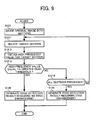
- Step S12 of generating an edge detection result is explained according to another exemplary embodiment of the present invention.
- the operation of FIG. 9 is substantially similar to the operation of FIG. 3 .
- the differences include replacement of Steps S122, S123, S124 with Steps S1211, S1212, S1213, and S1214.
- Step S1211 selects a target section S1 from the plurality of sections S.
- a target section S1 may be selected in the order from the top left to the bottom right of the original image.
- Step S1212 obtains a high frequency value F for the selected target section S1.
- the edge detector 12 first obtains a high frequency value F for the target section S11 positioned at the top left, which is the value "3".
- Step S1213 determines whether the high frequency value F is equal to or greater than a threshold frequency value T. If it is determined that the high frequency value F is equal to or greater than the threshold frequency value T ("YES" in Step S1213), the operation proceeds to Step S126 to generate not to apply edge enhancement. If the high frequency value F is less than the threshold frequency value T ("NO" in Step S1213), the operation proceeds to Step S1214.
- Step S1214 determines whether all sections S in the original image have been processed. If all sections S have been processed ("YES” in Step S1214), the operation proceeds to Step S125 to generate an edge detection result indicating to apply edge enhancement. If all sections S have not been processed ("NO” in Step S1214), the operation returns to Step S1211 to select a next target section S1.
- the edge detector 12 first determines whether the high frequency value 3 for the top left section S11 is equal to or greater than the threshold frequency value T, which is 10 in this example. Since the high frequency value 3 is less than 10 ("NO" in Step S1213), the operation proceeds to Step S1214 to select a next target section S12. This operation is repeated for the section S13, the section S14, and the Section S15.
- Step S15 Since the section S15 has the high frequency value 12, which is greater than 10 ("YES" in Step S1213), the operation proceeds to Step S126 to generate an edge detection result, which indicates not to apply edge enhancement.
- the processing speed may be reduced.
- Step S14 of applying edge enhancement may be performed in various ways.
- the image enhancer 13 of FIG. 1 may apply edge enhancement using a spatial filter illustrated in FIG. 11A .
- the pixel value f of the original image is adjusted as illustrated in the following equation.
- f ′ i j 5 ⁇ f i j ⁇ f ⁇ i ⁇ 1 , j ⁇ f ⁇ i + 1 , j ⁇ f ⁇ i , j ⁇ 1 ⁇ f ⁇ i , j + 1 , wherein ⁇ f ′ i j corresponds to the adjusted pixel value .
- the image enhancer 13 of FIG. 1 may apply edge enhancement using more than one spatial filter, which may be selected based on the high frequency value F obtained in Step S12 of FIG. 2 .
- the image enhancer 13 of FIG. 1 may select the spatial filter illustrated in FIG. 11A . If the target section S has a high frequency value F, which is equal to or less than the value 5, the image enhancer 13 of FIG. 1 may select a spatial filter illustrated in FIG. 11B . In this manner, the degree of edge enhancement can be adjusted depending on the characteristics of the original image, such as its edge intensity.
- the image enhancer 13 of FIG. 1 may select a spatial filter based on the edge direction of the original image, as illustrated in any one of FIG. 12 and FIG. 16 .
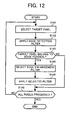
- Step S14 of applying edge enhancement is explained in more detail according to an exemplary embodiment of the present invention.
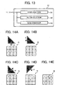
- the steps illustrated in FIG. 12 are performed by the image enhancer 13 having the structure shown in FIG. 13 .
- the image enhancer 13 includes an edge analyzer 131, a filter selector 132, and an edge enhancer 133.
- the edge analyzer 131 analyzes the original image to generate an analyzing result indicating an edge portion of the original image and the direction of the edge portion.
- the filter selector 132 selects a spatial filter based on the analyzing result generated by the edge analyzer 131.
- the edge enhancer 133 applies edge enhancement to the original image using the spatial filter selected by the filter selector 132, based on the analyzing result.
- Step S141 selects a target pixel in the original image.
- the target pixel may be selected in the order from the top left to the bottom right in the original image.
- Step S142 applies an edge detection filter to the target pixel to generate a filtered value, which indicates whether the target pixel belongs to an edge portion of the original image. Further, in this example, a plurality of spatial filters is used to detect the direction of the edge portion that includes the target pixel.
- the edge analyzer 131 applies a first edge detection filter f1, a second edge detection filter f2, a third edge detection filter f3, and a fourth edge detection filter f4, respectively to a target pixel P to generate a first filtered value fv1, a second filtered value fv2, a third filtered value fv3, and a fourth filtered value fv4.
- the first filtered value fv1 indicates whether the target pixel P belongs to the edge portion in the vertical direction.
- the second filtered value fv2 indicates whether the target pixel P belongs to the edge portion in the horizontal direction.
- the third filtered value fv3 indicates whether the target pixel P belongs to the edge portion in a first diagonal (the bottom left to the top right) direction.
- the fourth filtered value fv4 indicates whether the target pixel P belongs to the edge portion in a second diagonal (the top left to the bottom right) direction.
- Step S143 determines whether the target pixel belongs to the edge portion of the original image. If the target pixel belongs to the edge portion ("YES” in Step S143), the operation proceeds to Step S144. If the target pixel does not belong to the edge portion ("NO” in Step S143), the operation proceeds to Step S148.
- the edge analyzer 131 determines whether the target pixel P belongs to the edge portion using the first to fourth filtered values fv1 to fv4 obtained in Step S142. More specifically, in this example, the edge analyzer 131 selects one of the first to fourth filtered values fv1 to fv4, which has the largest value. The edge analyzer 131 then determines whether the largest filtered value is equal to or greater than a threshold filtered value. If the largest filtered value is equal to or greater than the threshold filtered value, the edge analyzer 131 determines that the target pixel P belongs to the edge portion in the direction of the largest filtered value, and the operation proceeds to Step S144. If the largest filtered value is less than the threshold filtered value, the edge analyzer 131 determines that the target pixel P does not belong to the edge portion, and the operation proceeds to Step S148.
- the third filtered value fv3 of 25, which is the largest, is compared with the threshold filtered value of 20. Since the third filtered value fv3 is greater than the threshold filtered value, the operation proceeds to Step S144.
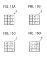
- Step S144 selects an edge enhancement filter based on the analyzing result generated by the edge analyzer 131 of FIG. 13 .
- the filter selector 132 selects a spatial filter corresponding to the direction of the edge portion that includes the target pixel P. For example, if the target pixel P belongs to the edge portion in the vertical direction, an edge enhancement filter for the vertical direction, such as a first edge enhancement filter f5 illustrated in FIG. 15A is selected. If the target pixel P belongs to the edge portion in the horizontal direction, an edge enhancement filter for the horizontal direction, such as a second edge enhancement filter f6 illustrated in FIG. 15B is selected.
- an edge enhancement filter for the first diagonal direction such as a third edge enhancement filter f7 illustrated in FIG. 15C is selected.
- an edge enhancement filter for the second diagonal direction such as a fourth edge enhancement filter f8 illustrated in FIG. 15D is selected.
- the third edge enhancement filter f7 is selected.
- Step S146 applies the selected edge enhancement filter to the target pixel.
- the third edge enhancement filter f7 is applied to the pixel values M to enhance the variance in pixel values in the first diagonal direction.
- Step S148 determines whether all pixels in the original image have been processed. If all pixels have been processed ("YES” in Step S148), the operation ends. If all pixels have not been processed ("NO” in Step S148), the operation returns to Step S141 to select a next target pixel in the original image.
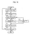
- Step S14 of applying edge enhancement is explained according to another exemplary embodiment of the present invention.
- the steps illustrated in FIG. 16 are performed by the image enhancer 13 having the structure shown in FIG. 17 .
- the image enhancer 13 includes the edge analyzer 131, the filter selector 132, the edge enhancer 133, and a smoother 134.
- the edge analyzer 131 analyzes the original image to generate an analyzing result indicating an edge portion of the original image and the direction of the edge portion. In this example, the analyzing result may further indicates a portion other than the edge portion of the original image as a non-edge portion.
- the filter selector 132 selects a spatial filter based on the analyzing result generated by the edge analyzer 131.
- the edge enhancer 133 applies edge enhancement to the edge portion of the original image, using the spatial filter selected by the filter selector 132.
- the smoother 134 applies smoothing to the non-edge portion, using the spatial filter selected by the filter selector 132.
- Step S141 selects a target pixel in the original image.
- Step S142 applies an edge detection filter to the target pixel to generate a plurality of filtered values in a substantially similar manner as described referring to Step S142 of FIG. 12 .
- Step S143 determines whether the target pixel belongs to the edge portion of the original image. If the target pixel belongs to the edge portion ("YES” in Step S143), the operation proceeds to Step S144. If the target pixel does not belong to the edge portion ("NO” in Step S143), the operation proceeds to Step S145.
- Step S144 selects an edge enhancement filter in a substantially similar manner as described referring to Step S144 of FIG. 12 .
- Step S145 selects a smoothing filter based on the analyzing result generated by the edge analyzer 131 of FIG. 17 .
- the filter selector 132 selects a spatial filter for smoothing the pixel value of the target pixel. In this manner, moiré or noise in the image may be suppressed.
- Step S147 applies the selected filter to the target pixel.
- the edge enhancement filter is selected in Step S144
- the edge enhancer 133 of FIG. 17 applies edge enhancement to the target pixel using the edge enhancement filter selected in Step S144.
- the smoother 134 of FIG. 17 applies smoothing to the target pixel using the smoothing filter selected in Step S145.
- Step S148 determines whether all pixels in the original image have been processed. If all pixels have been processed ("YES” in Step S148), the operation ends. If all pixels have not been processed ("NO” in Step S148), the operation returns to Step S141 to select a next target pixel in the original image.
- the image processing apparatus 10 of FIG. 1 may be implemented in various ways.
- the image processing apparatus 10 may be combined with other components as illustrated in any one of FIG. 18 and FIG. 20 .
- any one of the original image input 11, the edge detector 12, and the image enhancer 13 may operate independently, or they may be combined together into one component.
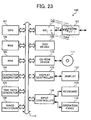
- the image processing apparatus 10 may be implemented by any kind of image processing system, for example, as a multifunctional apparatus (MFP) 100 shown in FIG. 23 .
- MFP multifunctional apparatus
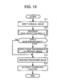
- FIG. 18 an image processing apparatus 20 is explained according to an exemplary embodiment of the present invention.
- the image processing apparatus 20 of FIG. 18 is substantially similar in functional structure to the image processing apparatus 10 of FIG. 1 , except for the addition of a binary image generator 14 and a character recognizer 15.
- the image processing apparatus 20 is capable of extracting a character portion of an original image, as illustrated in FIG. 19 , for example.
- Steps S11 to S14 are performed in a substantially similar manner as described referring to Steps S11 to S14 of FIG. 2 .
- Step S15 the binary image generator 14 generates a binary image from a processed image, which has been generated by the image enhancer 13 of FIG. 18 , using any kind of binarization method.
- Step S16 the character recognizer 15 extracts a character portion from the binary image, using any kind of character recognition method. Since the binary image is generated based on the processed image having the enhanced image quality as compared to the original image, the character portion can be extracted more accurately.
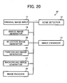
- FIG. 20 an image processing apparatus 30 is explained according to an exemplary embodiment of the present invention.
- the image processing apparatus 30 of FIG. 20 is substantially similar in functional structure to the image processing apparatus 10 of FIG. 1 , except for the addition of the binary image generator 14, a selection image generator 25, a foreground image generator 26, a background image generator 27, and an image encoder 28.
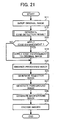
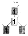
- the image processing apparatus 30 is capable of encoding an original image, as illustrated in FIG. 21 , for example.
- Steps S11 to S14 are performed in a substantially similar manner as described referring to Steps S11 to S14 of FIG. 2 .
- Step S25 the binary image generator 14 generates a binary image from a processed image, which has been generated by the image enhancer 13 of FIG. 20 , using any kind of binarization method.
- the selection image generator 25 generates a selection image, which may be used to segment the original image into a foreground image and a background image. For example, the selection image generator 25 extracts a character portion from the binary image using any kind of character recognition method. Once the character portion is extracted, the selection image generator 25 removes the unextracted portion, i.e., the non-character portion, of the binary image, such as by making the pixel values of the unextracted portion to become 0 or transparent. The resultant image is referred to as the selection image.
- the foreground image generator 26 generates the foreground image from the original image, using the selection image. For example, as illustrated in FIG. 22 , if an original image I0 and a selection image Is are provided, the foreground image generator 26 generates a foreground image If in the following manner. The foreground image generator 26 determines whether a target pixel in the foreground image If belongs to the character portion using the selection image Is. If the target pixel belongs to the character portion, the foreground image generator 26 assigns the pixel value, which can be obtained from the original image I0, to the target pixel. If the target pixel does not belong to the character portion, the foreground image generator 26 assigns the target pixel with the pixel value, which has been previously determined, such as the value corresponding to the black color, for example.
- the background image generator 27 generates the background image from the original image, using the selection image.
- the background image generator 27 generates a background image Ib in the following manner.
- the background image generator 27 determines whether a target pixel in the background image Ib belongs to the non-character portion using the selection image Is. If the target pixel belongs to the non-character portion, the background image generator 27 assigns the pixel value, which can be obtained from the original image I0, to the target pixel. If the target pixel does not belong to the non-character potion, the background image generator 27 assigns the target pixel with the pixel value, which has been previously determined, such as the value corresponding to the white color, for example.
- Step S29 the image encoder 28 encodes the foreground image and the background image, respectively.
- the foreground image may be encoded using the MMR compression method
- the background image may be encoded using the JPEG method.
- the foreground image, the background image, and the selection image may be stored in a corresponding manner for further use.
- the foreground image, the background image, and the selection image may be combined together using the JPEG 2000 multilayer (JPM) method for display.
- JPM JPEG 2000 multilayer
- FIG. 23 the structure of the MFP 1 is explained according to an exemplary embodiment of the present invention.
- the MFP 100 includes a central processing unit (CPU) 101, a read only memory (ROM) 102, a random access memory (RAM) 103, a character generator 104, a time data generator 105, an image processor 106, a network interface (I/F) 107, a network interface controller (NIC) 108, a disk device 109, a CD-ROM device 110, a display 112, a display controller 113, a keyboard 114, an operation panel 115, and an input controller 116, which are connected via a bus 117.
- CPU central processing unit
- ROM read only memory
- RAM random access memory
- 104 a character generator
- time data generator 105 a time data generator 105
- an image processor 106 a network interface (I/F) 107, a network interface controller (NIC) 108, a disk device 109, a CD-ROM device 110, a display 112, a display controller 113, a keyboard 114, an operation panel 115, and an input controller 116
- the CPU 101 controls operation of MFP 100.
- the ROM 102 stores various data, such as various computer programs to be executed by the CPU 101.
- the RAM 103 functions as a work memory of the CPU 101.
- the character generator 104 generates character data, which may be displayed by the display 112.
- the time data generator 105 outputs a current time or date, for example.
- the image processor 106 performs various image processing, such as edge enhancement or smoothing, for example.
- the network I/F 107 connects the MFP 1 to a network, such as a local area network or the Internet.
- the NIC 108 controls network connection, such as various communication protocols, to allow the MFP 1 to communicate via the network.
- the disk device 109 stores various data, such as various application programs, work data, file data, image data, etc.
- the CD-ROM 110 reads out data from a removable medium, such as an optical disc 111.
- the display 112 displays various data, which relates to the operation of the MFP 1.
- the display controller 113 controls data to be displayed by the display 112.
- the keyboard 114 allows a user to input various data, such as numerical or character data, for example.
- the operation panel 115 allows the user to input various data, using various keys or buttons, for example.
- the input controller 116 inputs data received from the user through the keyboard 114 or the operation panel 115.
- an image processing program of the present invention may be previously stored in the ROM 102. Upon execution, the CPU 101 may load the image processing program to operate as any one of the image processing apparatuses 10, 20, and 30. Alternatively, the image processing program may be downloaded from the network via the network I/F 107. Further, the image processing program may be uploaded to the network to cause another apparatus to operate as any one of the image processing apparatuses 10, 20, and 30.
- any one of the above-described and other methods of the present invention may be embodied in the form of a computer program stored in any kind of storage medium.
- storage mediums include, but are not limited to, flexible disk, hard disk, optical discs, magneto-optical discs, magnetic tapes, cassette tapes, non-volatile memory cards, optical memory cards, ROM (read-only-memory), non-volatile memory, etc.
- any one of the above-described and other methods of the present invention may be implemented by ASIC, prepared by interconnecting an appropriate network of conventional component circuits or by a combination thereof with one or more conventional general purpose microprocessors and/or signal processors programmed accordingly.
Landscapes
- Engineering & Computer Science (AREA)
- Physics & Mathematics (AREA)
- General Physics & Mathematics (AREA)
- Theoretical Computer Science (AREA)
- Computer Vision & Pattern Recognition (AREA)
- Facsimile Image Signal Circuits (AREA)
- Image Processing (AREA)
- Picture Signal Circuits (AREA)
Claims (4)
- Bildverarbeitungsverfahren, das die folgenden Schritte umfasst:Eingeben eines Originalbildes;Unterteilen des Originalbildes in mehrere Abschnitte;Umsetzen des Originalbildes von einem räumlichen Bereich in einen Frequenzbereich, um Hochfrequenzwerte für jeden der mehreren Abschnitte zu erhalten;Analysieren der Hochfrequenzwerte durch Wählen eines maximalen Frequenzwertes aus den mehreren Hochfrequenzwerten; undBestimmen, ob der maximale Frequenzwert niedriger als ein Schwellenfrequenzwert ist;Bestimmen, ob eine Kantenverbesserung auf das Originalbild angewendet werden soll, wobei die Kantenverbesserung angewendet wird, falls der maximale Frequenzwert niedriger als die Schwelle ist; undAnwenden einer Kantenverbesserung auf das Originalbild, wenn dies bestimmt wird;
dadurch gekennzeichnet, dass:der Schwellenfrequenzwert anhand der Auflösung des Originalbildes bestimmt wird. - Verfahren nach Anspruch 1, wobei der Anwendungsschritt die folgenden Schritte umfasst:Auswählen eines Kantenverbesserungsfilters anhand des Hochfrequenzwertes; undAnwenden des Kantenverbesserungsfilters auf das Originalbild.
- Bildverarbeitungsvorrichtung, die dafür ausgelegt ist, ein Verfahren nach Anspruch 1 oder 2 auszuführen.
- Computerprogramm, das Programmcodemittel enthält, die dann, wenn sie auf einem Computersystem ausgeführt werden, das Computersystem anweisen, das Verfahren nach einem der Ansprüche 1 oder 2 auszuführen.
Applications Claiming Priority (2)
| Application Number | Priority Date | Filing Date | Title |
|---|---|---|---|
| JP2005025350A JP2006217058A (ja) | 2005-02-01 | 2005-02-01 | 画像処理装置、画像処理方法、プログラムおよび記録媒体 |
| JP2005027452A JP2006215785A (ja) | 2005-02-03 | 2005-02-03 | 画像処理方法、画像処理装置、画像処理プログラム、および、記録媒体 |
Publications (3)
| Publication Number | Publication Date |
|---|---|
| EP1686536A2 EP1686536A2 (de) | 2006-08-02 |
| EP1686536A3 EP1686536A3 (de) | 2011-08-24 |
| EP1686536B1 true EP1686536B1 (de) | 2012-07-25 |
Family
ID=36155445
Family Applications (1)
| Application Number | Title | Priority Date | Filing Date |
|---|---|---|---|
| EP06250504A Ceased EP1686536B1 (de) | 2005-02-01 | 2006-01-31 | Anwendung von Kantenverstärkung auf Basis von Bildeigenschaften |
Country Status (2)
| Country | Link |
|---|---|
| US (1) | US7848589B2 (de) |
| EP (1) | EP1686536B1 (de) |
Families Citing this family (8)
| Publication number | Priority date | Publication date | Assignee | Title |
|---|---|---|---|---|
| JP4750047B2 (ja) * | 2006-03-31 | 2011-08-17 | 株式会社リコー | 位置ずれ検出装置、位置ずれ検出方法、位置ずれ検出プログラムおよび記録媒体 |
| JP4960897B2 (ja) * | 2008-01-30 | 2012-06-27 | 株式会社リコー | 画像処理装置、画像処理方法、プログラム、記憶媒体 |
| KR20100039761A (ko) * | 2008-10-08 | 2010-04-16 | 삼성전자주식회사 | 영상처리 장치 및 방법 |
| JP5462522B2 (ja) * | 2009-05-07 | 2014-04-02 | キヤノン株式会社 | 画像処理装置、画像処理方法、当該画像処理方法をコンピュータに実現させるためのプログラム |
| JP6115214B2 (ja) * | 2012-05-22 | 2017-04-19 | 株式会社リコー | パターン処理装置、パターン処理方法、パターン処理プログラム |
| JP6381311B2 (ja) * | 2013-07-04 | 2018-08-29 | キヤノン株式会社 | 画像形成装置、画像形成方法、およびプログラム |
| US9576346B2 (en) * | 2015-03-24 | 2017-02-21 | Intel Corporation | Non-local means image denoising with an adaptive directional spatial filter |
| CN112488940A (zh) * | 2020-11-30 | 2021-03-12 | 哈尔滨市科佳通用机电股份有限公司 | 一种铁路机车部件图像边缘增强方法 |
Family Cites Families (24)
| Publication number | Priority date | Publication date | Assignee | Title |
|---|---|---|---|---|
| JPS633562A (ja) | 1986-06-23 | 1988-01-08 | Ricoh Co Ltd | エツジ強調方式 |
| JP2611012B2 (ja) | 1989-09-19 | 1997-05-21 | 日本電信電話株式会社 | 文字分離符号化方法 |
| US5189523A (en) * | 1989-11-27 | 1993-02-23 | Canon Kabushiki Kaisha | Image processing apparatus |
| JP3253356B2 (ja) | 1992-07-06 | 2002-02-04 | 株式会社リコー | 文書画像の領域識別方法 |
| JP3359390B2 (ja) * | 1993-09-27 | 2002-12-24 | 株式会社リコー | 空間フィルタ装置 |
| JP2738818B2 (ja) | 1994-07-15 | 1998-04-08 | 松下電送株式会社 | 画信号処理装置 |
| JPH08163365A (ja) | 1994-11-29 | 1996-06-21 | Mita Ind Co Ltd | 画像処理装置 |
| JP3192407B2 (ja) | 1995-09-25 | 2001-07-30 | 松下電器産業株式会社 | 画像表示方法及びその装置 |
| JP3003561B2 (ja) | 1995-09-25 | 2000-01-31 | 松下電器産業株式会社 | 階調変換方法及びその回路と画像表示方法及びその装置と画像信号変換装置 |
| JP3468966B2 (ja) | 1996-01-19 | 2003-11-25 | 株式会社リコー | 画像処理装置 |
| EP0891075A3 (de) * | 1997-06-09 | 2002-03-06 | Seiko Epson Corporation | Bildverarbeitungsgerät und -verfahren sowie Bildauswertungsvorrichtung und -verfahren |
| JP4046465B2 (ja) | 1999-09-17 | 2008-02-13 | 株式会社リコー | 画像処理装置、画像処理方法、及び画像処理システム |
| JP4106843B2 (ja) | 2000-01-28 | 2008-06-25 | コニカミノルタビジネステクノロジーズ株式会社 | 画像処理装置 |
| JP4064031B2 (ja) | 2000-01-31 | 2008-03-19 | 富士フイルム株式会社 | 画像処理方法 |
| JP2001292325A (ja) | 2000-04-06 | 2001-10-19 | Casio Comput Co Ltd | エッジ強調装置、エッジ強調方法および記録媒体 |
| JP4099936B2 (ja) | 2000-09-07 | 2008-06-11 | 富士ゼロックス株式会社 | 画像処理装置、画像処理方法および画像処理プログラムが格納された記録媒体 |
| JP2002112036A (ja) | 2000-09-29 | 2002-04-12 | Sharp Corp | 画像処理装置 |
| JP4112187B2 (ja) | 2001-03-01 | 2008-07-02 | 富士フイルム株式会社 | 画像処理方法および装置並びにプログラム |
| JP4502303B2 (ja) | 2001-07-05 | 2010-07-14 | 株式会社リコー | 画像処理装置 |
| JP2003203232A (ja) | 2002-01-08 | 2003-07-18 | Noritsu Koki Co Ltd | 画像処理装置、画像処理プログラム、および画像処理プログラムを記録した記録媒体 |
| JP2004112603A (ja) * | 2002-09-20 | 2004-04-08 | Ricoh Co Ltd | 画像処理装置、画像処理方法、およびコンピュータが実行するためのプログラム |
| US7181082B2 (en) | 2002-12-18 | 2007-02-20 | Sharp Laboratories Of America, Inc. | Blur detection system |
| EP1555804A3 (de) * | 2004-01-19 | 2006-08-16 | Ricoh Company, Ltd. | Bildverarbeitungsvorrichtung, Bildverarbeitungsprogramm und Speichermedium |
| JP4111926B2 (ja) * | 2004-03-09 | 2008-07-02 | 株式会社リコー | 画像処理装置、プログラム、記憶媒体及び画像送信方法 |
-
2006
- 2006-01-31 EP EP06250504A patent/EP1686536B1/de not_active Ceased
- 2006-01-31 US US11/342,639 patent/US7848589B2/en not_active Expired - Fee Related
Also Published As
| Publication number | Publication date |
|---|---|
| EP1686536A3 (de) | 2011-08-24 |
| US7848589B2 (en) | 2010-12-07 |
| US20060170979A1 (en) | 2006-08-03 |
| EP1686536A2 (de) | 2006-08-02 |
Similar Documents
| Publication | Publication Date | Title |
|---|---|---|
| JP4423298B2 (ja) | デジタル画像におけるテキスト状エッジの強調 | |
| US7139437B2 (en) | Method and system for removing artifacts in compressed images | |
| EP0747855B1 (de) | Verfahren und Vorrichtung zur Verbesserung eines digitalen Bildes | |
| KR100422939B1 (ko) | 화상 부호화장치, 화상 복호화장치, 화상 부호화방법,화상 복호화방법 및 매체 | |
| KR101437195B1 (ko) | 코딩된 화상 및 영상에서 블록 아티팩트 검출 | |
| US8594451B2 (en) | Edge mapping incorporating panchromatic pixels | |
| US7257271B2 (en) | Noise reduction in color digital images using pyramid decomposition | |
| JP3465226B2 (ja) | 画像濃度変換処理方法 | |
| US6839151B1 (en) | System and method for color copy image processing | |
| US20030179409A1 (en) | Image processing apparatus, image processing program and storage medium storing the program | |
| EP1173003A2 (de) | Bildverarbeitungsverfahren und Bildverarbeitungsvorrichtung | |
| US20060092474A1 (en) | System and method for image processing | |
| EP1686536B1 (de) | Anwendung von Kantenverstärkung auf Basis von Bildeigenschaften | |
| JP2004159311A (ja) | 画像処理装置および画像処理方法 | |
| JPH06130513A (ja) | フィルム形式を識別する方法 | |
| JP5024574B2 (ja) | 画像処理装置及び画像処理プログラム | |
| KR101717733B1 (ko) | Hdr 이미지 처리 장치 및 방법 | |
| JP4264051B2 (ja) | 画像処理装置 | |
| US7463785B2 (en) | Image processing system | |
| JPH0879517A (ja) | 画像の型を識別する方法 | |
| CN109175718B (zh) | 一种基于半色调技术的图片激光雕刻方法 | |
| US6750986B1 (en) | Color image processing method with thin-line detection and enhancement | |
| JP3142279B2 (ja) | 網点領域分離装置 | |
| JP4001261B2 (ja) | 画像処理装置および方法 | |
| US6778296B1 (en) | Color imaging processing method with boundary detection and enhancement |
Legal Events
| Date | Code | Title | Description |
|---|---|---|---|
| PUAI | Public reference made under article 153(3) epc to a published international application that has entered the european phase |
Free format text: ORIGINAL CODE: 0009012 |
|
| 17P | Request for examination filed |
Effective date: 20060215 |
|
| AK | Designated contracting states |
Kind code of ref document: A2 Designated state(s): AT BE BG CH CY CZ DE DK EE ES FI FR GB GR HU IE IS IT LI LT LU LV MC NL PL PT RO SE SI SK TR |
|
| AX | Request for extension of the european patent |
Extension state: AL BA HR MK YU |
|
| RIN1 | Information on inventor provided before grant (corrected) |
Inventor name: UCHIYAMA, YUKIO Inventor name: HASEGAWA, FUMIHIRO,RICOH COMPANY LTD. |
|
| PUAL | Search report despatched |
Free format text: ORIGINAL CODE: 0009013 |
|
| AK | Designated contracting states |
Kind code of ref document: A3 Designated state(s): AT BE BG CH CY CZ DE DK EE ES FI FR GB GR HU IE IS IT LI LT LU LV MC NL PL PT RO SE SI SK TR |
|
| AX | Request for extension of the european patent |
Extension state: AL BA HR MK YU |
|
| RIC1 | Information provided on ipc code assigned before grant |
Ipc: G06T 5/10 20060101AFI20110720BHEP Ipc: G06T 7/00 20060101ALI20110720BHEP |
|
| GRAP | Despatch of communication of intention to grant a patent |
Free format text: ORIGINAL CODE: EPIDOSNIGR1 |
|
| AKX | Designation fees paid |
Designated state(s): DE GB |
|
| GRAS | Grant fee paid |
Free format text: ORIGINAL CODE: EPIDOSNIGR3 |
|
| GRAA | (expected) grant |
Free format text: ORIGINAL CODE: 0009210 |
|
| AK | Designated contracting states |
Kind code of ref document: B1 Designated state(s): DE GB |
|
| REG | Reference to a national code |
Ref country code: GB Ref legal event code: FG4D |
|
| REG | Reference to a national code |
Ref country code: DE Ref legal event code: R096 Ref document number: 602006030931 Country of ref document: DE Effective date: 20120920 |
|
| PLBE | No opposition filed within time limit |
Free format text: ORIGINAL CODE: 0009261 |
|
| STAA | Information on the status of an ep patent application or granted ep patent |
Free format text: STATUS: NO OPPOSITION FILED WITHIN TIME LIMIT |
|
| 26N | No opposition filed |
Effective date: 20130426 |
|
| REG | Reference to a national code |
Ref country code: DE Ref legal event code: R097 Ref document number: 602006030931 Country of ref document: DE Effective date: 20130426 |
|
| PGFP | Annual fee paid to national office [announced via postgrant information from national office to epo] |
Ref country code: DE Payment date: 20180122 Year of fee payment: 13 Ref country code: GB Payment date: 20180119 Year of fee payment: 13 |
|
| REG | Reference to a national code |
Ref country code: DE Ref legal event code: R119 Ref document number: 602006030931 Country of ref document: DE |
|
| GBPC | Gb: european patent ceased through non-payment of renewal fee |
Effective date: 20190131 |
|
| PG25 | Lapsed in a contracting state [announced via postgrant information from national office to epo] |
Ref country code: DE Free format text: LAPSE BECAUSE OF NON-PAYMENT OF DUE FEES Effective date: 20190801 |
|
| PG25 | Lapsed in a contracting state [announced via postgrant information from national office to epo] |
Ref country code: GB Free format text: LAPSE BECAUSE OF NON-PAYMENT OF DUE FEES Effective date: 20190131 |