EP1679475A1 - Dunstabzugshaube zur wandnahen Montage - Google Patents
Dunstabzugshaube zur wandnahen Montage Download PDFInfo
- Publication number
- EP1679475A1 EP1679475A1 EP05026565A EP05026565A EP1679475A1 EP 1679475 A1 EP1679475 A1 EP 1679475A1 EP 05026565 A EP05026565 A EP 05026565A EP 05026565 A EP05026565 A EP 05026565A EP 1679475 A1 EP1679475 A1 EP 1679475A1
- Authority
- EP
- European Patent Office
- Prior art keywords
- wall
- extractor hood
- housing
- hood according
- operating position
- Prior art date
- Legal status (The legal status is an assumption and is not a legal conclusion. Google has not performed a legal analysis and makes no representation as to the accuracy of the status listed.)
- Granted
Links
- 238000004140 cleaning Methods 0.000 claims abstract description 17
- 230000007704 transition Effects 0.000 claims description 6
- 238000009434 installation Methods 0.000 claims description 4
- 230000001174 ascending effect Effects 0.000 claims description 3
- 230000000630 rising effect Effects 0.000 claims description 3
- 238000000605 extraction Methods 0.000 abstract 2
- 238000011161 development Methods 0.000 description 7
- 230000018109 developmental process Effects 0.000 description 7
- 239000007789 gas Substances 0.000 description 6
- 239000002184 metal Substances 0.000 description 6
- 238000012546 transfer Methods 0.000 description 4
- 238000004891 communication Methods 0.000 description 2
- 239000003517 fume Substances 0.000 description 2
- 239000000463 material Substances 0.000 description 2
- 210000002105 tongue Anatomy 0.000 description 2
- 238000013459 approach Methods 0.000 description 1
- 230000005540 biological transmission Effects 0.000 description 1
- 238000013461 design Methods 0.000 description 1
- 239000011521 glass Substances 0.000 description 1
- 238000012423 maintenance Methods 0.000 description 1
- 238000004519 manufacturing process Methods 0.000 description 1
- 238000012549 training Methods 0.000 description 1
- 230000008016 vaporization Effects 0.000 description 1
Images

Classifications
-
- F—MECHANICAL ENGINEERING; LIGHTING; HEATING; WEAPONS; BLASTING
- F24—HEATING; RANGES; VENTILATING
- F24C—DOMESTIC STOVES OR RANGES ; DETAILS OF DOMESTIC STOVES OR RANGES, OF GENERAL APPLICATION
- F24C15/00—Details
- F24C15/20—Removing cooking fumes
- F24C15/2078—Removing cooking fumes movable
- F24C15/2092—Removing cooking fumes movable extendable or pivotable
Definitions
- the invention relates to an extractor hood for near-wall mounting referred to in the preamble of claim 1 Art.
- Such an extractor hood is known from EP 1 180 647 A1.
- the well-known extractor hood is arranged close to the wall in the installed position over a work area and has a housing in which a blower is installed.
- the lower end of the housing has an intake opening and an inflow element for ascending out of the working area vapors, wherein the inflow element extends substantially transversely to the rising vapors.
- the housing is pivotable about a horizontally extending axis away from the wall. At the same time thereby also in the operating position of the housing behind this wall surface is easier to access for cleaning purposes.
- the invention thus provides the problem of providing an extractor hood for near-wall mounting, in which a transfer of the hood from an operating position in a cleaning position for easier cleaning of the wall surface with structurally simple means allows while the required effort is reduced.
- the achievable with the present invention consist in addition to a structurally simple means made possible transfer of the hood of an operating position in a cleaning layer for easier cleaning of the wall surface and thereby simultaneously reduced effort especially in the thereby improved creative freedom. Since in the extractor hood according to the invention, only a portion of the housing must be moved during the transfer of the operating position in the cleaning position, the rest of the housing, based on the aforementioned transfer of the hood, largely free, that is without regard to mechanical or structural requirements and be designed on the applied by a user or a drive force. In this way, even very large extractor hoods can be realized without having to give up the possibility of cleaning the underlying wall surface.
- the structural design of the extractor hood according to the invention by type and material can be selected within wide suitable limits.
- the wall is close Part by means of a hinge pivotally held on the wall remote part or the rest of the housing.
- the wall-near part is in force transmission connection with a gas spring held articulated on the housing.
- the extractor hood according to the invention can be realized in a robust and low-maintenance manner.
- a particularly advantageous development of the aforementioned embodiment provides that the spring force of the gas spring whose attachment to the near-wall part, the position of the rotary joint and the mass of the wall-near part are coordinated such that the near-wall part both in its operating position as well as in the Cleaning layer is held automatically. In this way, no further components for fixing the near-wall part in the two layers mentioned are required.
- An advantageous development of the teaching according to the invention provides that the wall-near part, at least in the operating position, rests against a stop arranged on the wall-remote part or the rest of the housing. As a result, an undesired change in position of the wall-near part at least from the operating position is reliably prevented.
- the training and the arrangement of the attack on the type, size and material can be selected within wide suitable limits.
- the stop contacts the wall-near part in such a way that a force which is opposite to that exerted by the gas-pressure spring on the wall-near part is introduced into the wall-near part by the stop.
- the stop is realized in a particularly simple manner.
- the rotary joint has a bearing bush arranged on the wall-near part and a bearing bolt arranged on the wall-remote part or the remainder of the housing, wherein the bearing bolt has a substantially rectangular cross-section and the bearing bush has a free cross section corresponding thereto. the surface of which is obtainable by a rotation of the bearing pin about 40 ° in both directions of rotation about the axis of rotation of the rotary joint.
- the bearing pin can be formed without additional components from a part of the housing itself, without causing an undesirable play between bearing bush and bearing pin is formed.
- a further particularly advantageous embodiment provides that in the transition region of the two parts of the Anströmelements an intake opening is formed, which communicates with the fan in flow communication. In this way, the vapors flowing along the inflow element can be extracted in a streamlined manner.
- Another advantageous development provides that in the transition region of the two parts of the Anströmelements designed as a flow guide lamp is arranged, which promotes the movement of the flowing along the Anströmelement Wrasens towards at least one suction. As a result, the number of required components is reduced, since the light is used on the one hand for illuminating the work area and on the other hand as a flow guide for the flowing along the vaporizing fumes.
- An advantageous development of the teaching according to the invention provides that the wall-near part by means of a transport lock on the wall remote part or on the rest of the housing in one position can be locked. In this way it is ensured that the extractor hood according to the invention is not damaged during its transport, assembly or disassembly by the movable in the installation position of the hood near the wall.
- Fig. 1 shows an extractor hood according to the invention for near-wall mounting in its installed position.
- the extractor hood is arranged above a working area 2 and has a housing 6 attached to a fume hood 4, in which an unillustrated blower is arranged.
- the extractor hood has a plurality of intake openings 8 and an inflow element 10, wherein the inflow element 10 extends essentially transversely to the vapor rising above the work area 2.
- the ascending vapor is symbolized in FIG. 1 by arrows 11.
- the Anströmelement 10 has a far wall part 10.1 and a near-wall part 10.2, wherein in the illustrated installation position of the hood of the off-wall part 10.1 is immutable in its position.
- the wall-proximal part 10.2 is movably held on the part 10.1 remote from the wall and between an operating position shown in FIG. 1, in which the wall-proximate part 10.2 reaches up to a small gap to the wall surface, not shown in FIG. 1, and one in FIG cleaning layer, also not shown, in which the wall-near part 10.2 is spaced from the wall surface, that in the operating position of the near-wall part 10.2 through this hidden area of the wall surface is accessible to a human hand, movable back and forth.
- FIGS. 2 to 5 The details emerge from FIGS. 2 to 5 and the corresponding text passages.
- the extractor hood according to the invention can be seen in a side view, wherein in the designated "B" area, the housing 6 is shown partially broken.
- the wall near part 10.2 extends in the illustrated operating position except for a small gap on the wall surface 12, on which the hood is mounted in its installed position approach.
- the wall-near part 10.2 in this position of the extractor hood part of the wall surface 12 is covered by the wall-near part 10.2.
- a cleaning of this part of the wall surface 12 is made very difficult and without the use of special tools in conventional cooker hoods not possible.
- the distance between the near-wall part 10.2 and the wall surface 12 can not be reduced to zero due to manufacturing reasons and the different mounting conditions on site. The resulting problem is solved by the extractor hood according to the invention.
- the wall-proximate part 10.2 is held pivotably by means of a rotary joint 14 on the part 10.1 remote from the wall.
- the hinge 14 is shown in detail in Figs. 3 to 5.
- the wall-near part 10.2 is in force-transmitting connection with a gas pressure spring 16, which is held in an articulated manner on the housing 6.
- a trained as a sheet metal angle lever arm 17 is fixed in a manner known in the art to the near-wall part 10.2, which is designed as a glass plate, which is explained in more detail with reference to FIGS. 3 and 4.
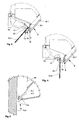
- Fig. 3 shows the detail "B" of Fig. 2 in an enlarged view.
- the near-wall part 10.2 abuts against a stop 18 located on the wall-remote part 10.1, the stop 18 contacting the near-wall part 10.2 in such a way that a stop 10 results in a stop being caused by the gas spring 16 on the wall-proximate part 10.2 applied force opposite force is introduced into the near-wall part 10.2.
- the extractor hood according to the invention is still shown with activated transport lock.
- arranged on the wall remote part 10.1 and designed as a sheet metal angle stop 18 a projection 18.1, in which a not visible in Fig. 3 longitudinal opening is formed.
- the lever arm 17 engages with a hook formed thereon in the longitudinal opening and locked with the projection 18.1.
- the lever arm 17 is shown in Fig. 4 in detail.
- the transport lock must be solved.
- the projection 18.1 in the direction of the Lever arm 17 bent away side bent until the hook with the projection 18.1 is no longer engaged.
- an intake opening 8 is formed in the transition region of the two parts 10.1 and 10.2 of the inflow element 10, which is in flow communication with the blower, not shown.
- the transition region of the two parts 10.1 and 10.2 of the Anströmelements 10 designed as a flow guide lamp 20 is arranged, which promotes the movement of the flowing along the Anströmelement 10 Wrasens in the direction of the intake 8.
- the lamp 20 is designed as a light strip, which is shown in Fig. 3 in cross section.
- Fig. 4 the near-wall part 10.2 is shown in its rest position.
- the exact shape of the designed as a sheet-metal angle lever arm 17 is clearly apparent from Fig. 4.
- the near-wall part 10.2 abuts against a stop 22 in its rest position.
- the stop 22 contacts the wall-proximal part 10.2 in such a way that a force opposing the force exerted by the gas pressure spring 16 on the wall-proximate part 10.2 is introduced into the wall-proximal part 10.2 by the stop 22.
- Fig. 5 shows the hinge 14 in detail, with the near-wall part 10.2 is in the cleaning position.
- the rotary joint 14 has two bearing bushes 14.1 arranged on the wall-proximal part 10.1 and two bearing bolts 14.2 arranged on the wall-distant part 10.1 and designed as sheet metal tongues, with only one bearing bush 14.1 and one bearing bolt 14.2 being shown in a side view in FIG.
- the bearing pins 14.2 have a substantially rectangular cross section and the bearing bushes 14.1 have a corresponding free cross section, the surface of which is obtainable by a rotation of the respective bearing pin 14.2 by about 40 ° in both directions of rotation about the pivot 14.
- the axis of rotation is symbolized in FIG. 5 by two crossed and dashed lines 24.
- the bearing bushes 14.1 are formed as openings in the wall-near part 10.2 fixed sheet metal bracket 26.
- the sheet metal tongues are formed in a manner known to those skilled in the art from the wall of the housing 6.
- one or more of a bearing bush 14.1 and a bearing pin 14.2 existing pairings for forming the pivot joint 14 are required.
Landscapes
- Engineering & Computer Science (AREA)
- Chemical & Material Sciences (AREA)
- Combustion & Propulsion (AREA)
- Mechanical Engineering (AREA)
- General Engineering & Computer Science (AREA)
- Ventilation (AREA)
Abstract
Description
- Die Erfindung betrifft eine Dunstabzugshaube zur wandnahen Montage der im Oberbegriff des Anspruchs 1 genannten Art.
- Eine derartige Dunstabzugshaube ist aus der EP 1 180 647 A1 bekannt. Die bekannte Dunstabzugshaube ist in deren Einbaulage wandnah über einem Arbeitsbereich angeordnet und weist ein Gehäuse auf, in dem ein Gebläse eingebaut ist. Das untere Ende des Gehäuses weist eine Ansaugöffnung und ein Anströmelement für aus dem Arbeitsbereich aufsteigenden Wrasen auf, wobei das Anströmelement im Wesentlichen quer zu dem aufsteigenden Wrasen verläuft. Um die Innenreinigung des Gehäuses zu erleichtern, ist das Gehäuse um eine horizontal verlaufende Achse von der Wand weg schwenkbar. Gleichzeitig wird hierdurch auch die in der Betriebslage des Gehäuses hinter diesem befindliche Wandfläche für Reinigungszwecke leichter zugänglich.
- Der Erfindung stellt sich somit das Problem eine Dunstabzugshaube zur wandnahen Montage anzugeben, bei der eine Überführung der Dunstabzugshaube von einer Betriebslage in eine Reinigungslage zur leichteren Reinigung der Wandfläche mit konstruktiv einfachen Mitteln ermöglicht und gleichzeitig der dabei erforderliche Kraftaufwand verringert ist.
- Erfindungsgemäß wird dieses Problem durch eine Dunstabzugshaube zur wandnahen Montage mit den Merkmalen des Patentanspruchs 1 gelöst. Vorteilhafte Ausgestaltungen und Weiterbildungen der Erfindung ergeben sich aus den nachfolgenden Unteransprüchen.
- Die mit der Erfindung erreichbaren Vorteile bestehen neben einer mit konstruktiv einfachen Mitteln ermöglichten Überführung der Dunstabzugshaube von einer Betriebslage in eine Reinigungslage zur leichteren Reinigung der Wandfläche und einem dabei gleichzeitig verringerten Kraftaufwand insbesondere in der dadurch verbesserten gestalterischen Freiheit. Da bei der erfindungsgemäßen Dunstabzugshaube lediglich ein Teil des Gehäuses bei der Überführung von der Betriebslage in die Reinigungslage bewegt werden muss, kann der Rest des Gehäuses, bezogen auf die vorgenannte Überführung der Dunstabzugshaube, weitestgehend frei, dass heißt ohne Rücksicht auf mechanische oder konstruktive Erfordernisse sowie auf die von einem Benutzer oder einem Antrieb aufzubringende Kraft, gestaltet werden. Auf diese Weise sind auch sehr große Dunstabzugshauben realisierbar, ohne auf die Möglichkeit der Reinigung der dahinter liegenden Wandfläche verzichten zu müssen.
- Grundsätzlich ist die konstruktive Ausbildung der erfindungsgemäßen Dunstabzugshaube nach Art und Material in weiten geeigneten Grenzen wählbar. Zweckmäßigerweise ist der wandnahe Teil mittels eines Drehgelenks schwenkbeweglich an dem wandfernen Teil oder dem Rest des Gehäuses gehalten.
- Eine vorteilhafte Weiterbildung der vorgenannten Ausführungsform sieht vor, dass der wandnahe Teil mit einer an dem Gehäuse gelenkig gehaltenen Gasdruckfeder in Kraftübertragungsverbindung steht. Hierdurch ist die erfindungsgemäße Dunstabzugshaube auf eine robuste und wartungsarme Weise realisierbar.
- Eine besonders vorteilhafte Weiterbildung der vorgenannten Ausführungsform sieht vor, dass die Federkraft der Gasdruckfeder, deren Befestigung an dem wandnahen Teil, die Lage des Drehgelenks und die Masse des wandnahen Teils derart aufeinander abgestimmt sind, dass der wandnahe Teil sowohl in dessen Betriebslage wie auch in dessen Reinigungslage selbsttätig gehalten ist. Auf diese Weise sind keine weiteren Bauteile zur Fixierung des wandnahen Teils in den beiden genannten Lagen erforderlich.
- Eine vorteilhafte Weiterbildung der erfindungsgemäßen Lehre sieht vor, dass der wandnahe Teil wenigstens in der Betriebslage an einem an dem wandfernen Teil oder dem Rest des Gehäuses angeordneten Anschlag anliegt. Hierdurch ist eine ungewünschte Lageänderung des wandnahen Teils zumindest aus der Betriebslage sicher verhindert.
- Grundsätzlich ist die Ausbildung und die Anordnung des Anschlags nach Art, Größe und Material in weiten geeigneten Grenzen wählbar. Vorteilhafterweise kontaktiert der Anschlag den wandnahen Teil derart, dass durch den Anschlag eine zu der durch die Gasdruckfeder auf den wandnahen Teil ausgeübte Kraft entgegengesetzte Kraft in das wandnahe Teil eingeleitet wird. Hierdurch ist der Anschlag auf besonders einfache Weise verwirklicht.
- Eine besonders vorteilhafte Weiterbildung sieht vor, dass das Drehgelenk eine an dem wandnahen Teil angeordnete Lagerbuchse und einen an dem wandfernen Teil oder dem Rest des Gehäuses angeordneten Lagerbolzen aufweist, wobei der Lagerbolzen einen im Wesentlichen rechteckigen Querschnitt und die Lagerbuchse einen dazu korrespondierenden freien Querschnitt aufweist, dessen Fläche durch eine Drehung des Lagerbolzens um etwa 40° in beide Drehrichtungen um die Drehachse des Drehgelenks erhältlich ist. Hierdurch kann der Lagerbolzen ohne zusätzliche Bauteile aus einem Teil des Gehäuses selbst gebildet werden, ohne dass dadurch ein ungewünschtes Spiel zwischen Lagerbuchse und Lagerbolzen entsteht.
- Eine weitere besonders vorteilhafte Weiterbildung sieht vor, dass in dem Übergangsbereich der beiden Teile des Anströmelements eine Ansaugöffnung ausgebildet ist, die mit dem Gebläse in Strömungsverbindung steht. Auf diese Weise kann der an dem Anströmelement entlang strömende Wrasen strömungsgünstig abgesaugt werden.
- Eine andere vorteilhafte Weiterbildung sieht vor, dass in dem Übergangsbereich der beiden Teile des Anströmelements eine als Strömungsleitelement ausgebildete Leuchte angeordnet ist, die die Bewegung des an dem Anströmelement entlang strömenden Wrasens in Richtung mindestens einer Ansaugöffnung fördert. Hierdurch ist die Anzahl der erforderlichen Bauteile reduziert, da die Leuchte zum einen zur Beleuchtung des Arbeitsbereichs und zum anderen als Strömungsleitelement für den an dem Anströmelement entlang strömenden Wrasen dient.
- Eine vorteilhafte Weiterbildung der erfindungsgemäßen Lehre sieht vor, dass das wandnahe Teil mittels einer Transportsicherung an dem wandfernen Teil oder an dem Rest des Gehäuses in einer Lage arretierbar ist. Auf diese Weise ist gewährleistet, dass die erfindungsgemäße Dunstabzugshaube bei deren Transport, Montage oder Demontage nicht durch das in der Einbaulage der Dunstabzugshaube bewegbare wandnahe Teil beschädigt wird.
- Ein Ausführungsbeispiel der Erfindung ist in den Zeichnungen rein schematisch dargestellt und wird nachfolgend näher beschrieben. Es zeigt
- Figur 1
- eine Vorderansicht einer erfindungsgemäßen Dunstabzugshaube,
- Figur 2
- die Dunstabzugshaube aus Fig. 1 in einer Seitenansicht,
- Figur 3
- die Einzelheit B aus Fig. 2,
- Figur 4
- die Dunstabzugshaube in der Reinigungslage und in ähnlicher Darstellung wie in Fig. 3 und
- Figur 5
- die Einzelheit F aus Fig. 4.
- Die Fig. 1 zeigt eine erfindungsgemäße Dunstabzugshaube zur wandnahen Montage in deren Einbaulage. Die Dunstabzugshaube ist über einem Arbeitsbereich 2 angeordnet und weist ein an einem Abzugskamin 4 befestigtes Gehäuse 6 auf, in dem ein nicht dargestelltes Gebläse angeordnet ist. An dem in der Einbaulage der Dunstabzugshaube unterem Ende weist die Dunstabzugshaube mehrere Ansaugöffnungen 8 und ein Anströmelement 10 auf, wobei das Anströmelement 10 im Wesentlichen quer zu dem über dem Arbeitsbereich 2 aufsteigenden Wrasen verläuft. Der aufsteigende Wrasen ist in Fig. 1 durch Pfeile 11 symbolisiert. Das Anströmelement 10 weist ein wandfernes Teil 10.1 und ein wandnahes Teil 10.2 auf, wobei in der dargestellten Einbaulage der Dunstabzugshaube der wandferne Teil 10.1 in dessen Lage unveränderlich ist. Der wandnahe Teil 10.2 ist beweglich an dem wandfernen Teil 10.1 gehalten und zwischen einer in Fig. 1 dargestellten Betriebslage, in der der wandnahe Teil 10.2 bis auf einen kleinen Spalt an die in Fig. 1 nicht dargestellte Wandfläche heranreicht, und einer in Fig. 1 ebenfalls nicht dargestellten Reinigungslage, in der der wandnahe Teil 10.2 derart von der Wandfläche beabstandet ist, dass der in der Betriebslage des wandnahen Teils 10.2 durch diesen verdeckte Bereich der Wandfläche für eine menschliche Hand zugänglich ist, hin und her bewegbar. Die Details ergeben sich aus den Fig. 2 bis 5 und den entsprechenden Textstellen.
- In Fig. 2 ist die erfindungsgemäße Dunstabzugshaube in einer Seitenansicht zu sehen, wobei in dem mit "B" bezeichneten Bereich das Gehäuse 6 teilweise ausgebrochen dargestellt ist. Wie aus Fig. 2 deutlich hervorgeht, reicht der wandnahe Teil 10.2 in der dargestellten Betriebslage bis auf einen kleinen Spalt an die Wandfläche 12, an der die Dunstabzugshaube in deren Einbaulage montiert ist, heran. Wie aus den Fig. 1 und 2 ersichtlich ist, ist in dieser Lage der Dunstabzugshaube ein Teil der Wandfläche 12 durch den wandnahen Teil 10.2 verdeckt. Eine Reinigung dieses Teils der Wandfläche 12 ist dadurch sehr erschwert und ohne den Einsatz von speziellem Werkzeug bei herkömmlichen Dunstabzugshauben gar nicht möglich. Der Abstand zwischen dem wandnahen Teil 10.2 und der Wandfläche 12 kann aus fertigungstechnischen Gründen und den unterschiedlichen Montagebedingungen vor Ort jedoch nicht auf Null reduziert werden. Die sich daraus ergebende Problematik wird durch die erfindungsgemäße Dunstabzugshaube gelöst.
- Wie aus Fig. 2 ferner hervorgeht, ist der wandnahe Teil 10.2 mittels eines Drehgelenks 14 schwenkbeweglich an dem wandfernen Teil 10.1 gehalten. Das Drehgelenk 14 ist im Detail in den Fig. 3 bis 5 dargestellt. Des Weiteren steht der wandnahe Teil 10.2 mit einer an dem Gehäuse 6 gelenkig gehaltenen Gasdruckfeder 16 in Kraftübertragungsverbindung. Hierzu ist an dem wandnahen Teil 10.2, das als Glasscheibe ausgebildet ist, ein als Blechwinkel ausgebildeter Hebelarm 17 auf dem Fachmann bekannte Weise befestigt, der anhand der Fig. 3 und 4 näher erläutert wird. Bei dem vorliegenden Ausführungsbeispiel sind die Federkraft der Gasdruckfeder 16, deren Befestigung an dem wandnahen Teil 10.2, die Lage des Drehgelenks 14 und die Masse des wandnahen Teils 10.2 derart aufeinander abgestimmt, dass der wandnahe Teil 10.2 sowohl in dessen Betriebslage wie auch in dessen Reinigungslage selbsttätig gehalten ist.
- Fig. 3 zeigt die Einzelheit "B" aus Fig. 2 in vergrößerter Darstellung. In der hier dargestellten Betriebslage liegt der wandnahe Teil 10.2 an einem an dem wandfernen Teil 10.1 angeordneten Anschlag 18 an, wobei der Anschlag 18 den wandnahen Teil 10.2 derart kontaktiert, dass durch den Anschlag 18 eine zu der durch die Gasdruckfeder 16 auf den wandnahen Teil 10.2 ausgeübte Kraft entgegengesetzte Kraft in das wandnahe Teil 10.2 eingeleitet wird. In Fig. 3 ist die erfindungsgemäße Dunstabzugshaube noch mit aktivierter Transportsicherung dargestellt. Hierzu weist der an dem wandfernen Teil 10.1 angeordnete und als Blechwinkel ausgebildete Anschlag 18 einen Vorsprung 18.1 auf, in dem eine in der Fig. 3 nicht sichtbare Längsöffnung ausgebildet ist. In der dargestellten Betriebslage greift der Hebelarm 17 mit einem daran ausgebildeten Haken in die Längsöffnung ein und verrastet mit dem Vorsprung 18.1. Der Hebelarm 17 ist in Fig. 4 im Detail dargestellt. Vor der ersten Inbetriebnahme der erfindungsgemäßen Dunstabzugshaube gemäß dem vorliegenden Ausführungsbeispiel muss die Transportsicherung gelöst werden. Hierzu wird der Vorsprung 18.1 in Richtung der von dem Hebelarm 17 abgewandten Seite umgebogen, bis dass der Haken mit dem Vorsprung 18.1 nicht mehr in Eingriff ist.
- Bei dem vorliegenden Ausführungsbeispiel ist in dem Übergangsbereich der beiden Teile 10.1 und 10.2 des Anströmelements 10 eine Ansaugöffnung 8 ausgebildet, die mit dem nicht dargestellten Gebläse in Strömungsverbindung steht. Darüber hinaus ist in dem Übergangsbereich der beiden Teile 10.1 und 10.2 des Anströmelements 10 eine als Strömungsleitelement ausgebildete Leuchte 20 angeordnet, die die Bewegung des an dem Anströmelement 10 entlang strömenden Wrasens in Richtung der Ansaugöffnungen 8 fördert. Hierzu ist die Leuchte 20 als eine Leuchtenleiste ausgebildet, die in Fig. 3 im Querschnitt dargestellt ist.
- In Fig. 4 ist der wandnahe Teil 10.2 in dessen Ruhelage dargestellt. Die genaue Form des als Blechwinkel ausgebildeten Hebelarms 17 ist aus Fig. 4 deutlich ersichtlich. Bei dem vorliegenden Ausführungsbeispiel liegt der wandnahe Teil 10.2 in dessen Ruhelage an einem Anschlag 22 an. Analog zu der Betriebslage kontaktiert der Anschlag 22 den wandnahen Teil 10.2 derart, dass durch den Anschlag 22 eine zu der durch die Gasdruckfeder 16 auf den wandnahen Teil 10.2 ausgeübte Kraft entgegengesetzte Kraft in das wandnahe Teil 10.2 eingeleitet wird.
- Die Fig. 5 zeigt das Drehgelenk 14 im Detail, wobei sich das wandnahe Teil 10.2 in der Reinigungslage befindet. Das Drehgelenk 14 weist zwei an dem wandnahen Teil 10.2 angeordnete Lagerbuchsen 14.1 und zwei an dem wandfernen Teil 10.1 angeordnete und als Blechzungen ausgebildete Lagerbolzen 14.2 auf, wobei in Fig. 5 lediglich eine Lagerbuchse 14.1 und ein Lagerbolzen 14.2 in einer Seitenansicht dargestellt sind. Die Lagerbolzen 14.2 weisen einen im Wesentlichen rechteckigen Querschnitt und die Lagerbuchsen 14.1 einen dazu korrespondierenden freien Querschnitt auf, dessen Fläche durch eine Drehung des jeweiligen Lagerbolzens 14.2 um etwa 40° in beide Drehrichtungen um die Drehachse des Drehgelenks 14 erhältlich ist. Die Drehachse ist in Fig. 5 durch zwei gekreuzte und gestrichelte Linien 24 symbolisiert. Die Lagerbuchsen 14.1 sind als Öffnungen in an dem wandnahen Teil 10.2 befestigte Blechwinkel 26 ausgebildet. Die Blechzungen sind auf dem Fachmann bekannte Weise aus der Wand des Gehäuses 6 ausgeformt. Je nachdem, wie groß und wie schwer die erfindungsgemäße Dunstabzugshaube bzw. das wandnahe Teil 10.2 ist, sind eine oder mehrere aus einer Lagerbuchse 14.1 und einem Lagerbolzen 14.2 bestehende Paarungen zur Bildung des Drehgelenks 14 erforderlich.
Claims (10)
- Dunstabzugshaube zur wandnahen Montage über einem Arbeitsbereich, mit einem Gehäuse, in dem ein Gebläse angeordnet ist und dessen in der Einbaulage der Dunstabzugshaube unteres Ende wenigstens eine Ansaugöffnung und ein Anströmelement für aus dem Arbeitsbereich aufsteigenden Wrasen aufweist, wobei das Anströmelement im Wesentlichen quer zu dem aufsteigenden Wrasen verläuft und ein Teil des Gehäuses relativ zu der Wandfläche bewegbar ist,
dadurch gekennzeichnet,
dass das Anströmelement (10) ein wandnahes und ein wandfernes Teil (10.2, 10.1) aufweist, wobei in der Einbaulage der Dunstabzugshaube der wandferne Teil (10.1) in dessen Lage unveränderlich ist und der wandnahe Teil (10.2) beweglich an dem wandfernen Teil (10.1) oder an dem Rest des Gehäuses (6) gehalten ist und zwischen einer Betriebslage, in der der wandnahe Teil (10.2) bis auf einen kleinen Spalt an die Wandfläche (12) heranreicht, und einer Reinigungslage, in der der wandnahe Teil (10.2) derart von der Wandfläche (12) beabstandet ist, dass der in der Betriebslage des wandnahen Teils (10.2) durch diesen verdeckte Bereich der Wandfläche (12) für eine menschliche Hand zugänglich ist, hin und her bewegbar ist. - Dunstabzugshaube nach Anspruch 1,
dadurch gekennzeichnet,
dass der wandnahe Teil (10.2) mittels eines Drehgelenks (14) schwenkbeweglich an dem wandfernen Teil (10.1) oder dem Rest des Gehäuses (6) gehalten ist. - Dunstabzugshaube nach Anspruch 2,
dadurch gekennzeichnet,
dass der wandnahe Teil (10.2) mit einer an dem Gehäuse (6) gelenkig gehaltenen Gasdruckfeder (16) in Kraftübertragungsverbindung steht. - Dunstabzugshaube nach Anspruch 3,
dadurch gekennzeichnet,
dass die Federkraft der Gasdruckfeder (16), deren Befestigung an dem wandnahen Teil (10.2), die Lage des Drehgelenks (14) und die Masse des wandnahen Teils (10.2) derart aufeinander abgestimmt sind, dass der wandnahe Teil (10.2) sowohl in dessen Betriebslage wie auch in dessen Reinigungslage selbsttätig gehalten ist. - Dunstabzugshaube nach mindestens einem der Ansprüche 1 bis 4,
dadurch gekennzeichnet,
dass der wandnahe Teil (10.2) wenigstens in der Betriebslage an einem an dem wandfernen Teil (10.1) oder dem Rest des Gehäuses (6) angeordneten Anschlag (18, 22) anliegt. - Dunstabzugshaube nach Anspruch 5,
dadurch gekennzeichnet,
dass der Anschlag (18, 22) den wandnahen Teil (10.2) derart kontaktiert, dass durch den Anschlag (18, 22) eine zu der durch die Gasdruckfeder (16) auf den wandnahen Teil (10.2) ausgeübte Kraft entgegengesetzte Kraft in das wandnahe Teil (10.2) eingeleitet wird. - Dunstabzugshaube nach mindestens einem der Ansprüche 2 bis 6,
dadurch gekennzeichnet,
dass das Drehgelenk (14) eine an dem wandnahen Teil (10.2) angeordnete Lagerbuchse (14.1) und einen an dem wandfernen Teil (10.1) oder dem Rest des Gehäuses (6) angeordneten Lagerbolzen (14.2) aufweist, wobei der Lagerbolzen (14.2) einen im Wesentlichen rechteckigen Querschnitt und die Lagerbuchse (14.1) einen dazu korrespondierenden freien Querschnitt aufweist, dessen Fläche durch eine Drehung des Lagerbolzens (14.2) um etwa 40° in beide Drehrichtungen um die Drehachse (24) des Drehgelenks (14) erhältlich ist. - Dunstabzugshaube nach mindestens einem der Ansprüche 1 bis 7,
dadurch gekennzeichnet,
dass in dem Übergangsbereich der beiden Teile (10.1, 10.2) des Anströmelements (10) eine Ansaugöffnung (8) ausgebildet ist, die mit dem Gebläse in Strömungsverbindung steht. - Dunstabzugshaube nach mindestens einem der Ansprüche 1 bis 8,
dadurch gekennzeichnet,
dass in dem Übergangsbereich der beiden Teile (10.1, 10.2) des Anströmelements (10) eine als Strömungsleitelement ausgebildete Leuchte (20) angeordnet ist, die die Bewegung des an dem Anströmelement (10) entlang strömenden Wrasens in Richtung mindestens einer Ansaugöffnung (8) fördert. - Dunstabzugshaube nach mindestens einem der Ansprüche 1 bis 9,
dadurch gekennzeichnet,
dass das wandnahe Teil (10.2) mittels einer Transportsicherung (17, 18.1) an dem wandfesten Teil (10.1) oder an dem Rest des Gehäuses (6) in einer Lage arretierbar ist.
Priority Applications (1)
| Application Number | Priority Date | Filing Date | Title |
|---|---|---|---|
| PL05026565T PL1679475T3 (pl) | 2004-12-21 | 2005-12-06 | Okap wyciągu oparów do montażu blisko ściany |
Applications Claiming Priority (1)
| Application Number | Priority Date | Filing Date | Title |
|---|---|---|---|
| DE102004061374A DE102004061374B3 (de) | 2004-12-21 | 2004-12-21 | Dunstabzugshaube zur wandnahen Montage |
Publications (2)
| Publication Number | Publication Date |
|---|---|
| EP1679475A1 true EP1679475A1 (de) | 2006-07-12 |
| EP1679475B1 EP1679475B1 (de) | 2013-11-13 |
Family
ID=35825318
Family Applications (1)
| Application Number | Title | Priority Date | Filing Date |
|---|---|---|---|
| EP05026565.1A Expired - Lifetime EP1679475B1 (de) | 2004-12-21 | 2005-12-06 | Dunstabzugshaube zur wandnahen Montage |
Country Status (3)
| Country | Link |
|---|---|
| EP (1) | EP1679475B1 (de) |
| DE (1) | DE102004061374B3 (de) |
| PL (1) | PL1679475T3 (de) |
Cited By (3)
| Publication number | Priority date | Publication date | Assignee | Title |
|---|---|---|---|---|
| DE102006041582A1 (de) * | 2006-09-05 | 2008-03-06 | BSH Bosch und Siemens Hausgeräte GmbH | Dunstabzugshaube |
| CN109595645A (zh) * | 2017-09-30 | 2019-04-09 | 宁波方太厨具有限公司 | 一种近吸式吸油烟机 |
| CN116025933A (zh) * | 2021-10-27 | 2023-04-28 | 佛山市顺德区美的洗涤电器制造有限公司 | 油烟机 |
Families Citing this family (3)
| Publication number | Priority date | Publication date | Assignee | Title |
|---|---|---|---|---|
| DE102009001187A1 (de) * | 2009-02-26 | 2010-09-02 | BSH Bosch und Siemens Hausgeräte GmbH | Adapter für ein Befestigungsgestell einer Dunstabzugshaube, insbesondere einer Inseldunstabzugshaube |
| CN203323210U (zh) * | 2013-06-24 | 2013-12-04 | 佛山市顺德区合捷电器实业有限公司 | 一种具有面板防夹功能的油烟机 |
| DE102018129117A1 (de) * | 2018-11-20 | 2020-05-20 | Miele & Cie. Kg | Solitäre Wanddunstabzugshaube |
Citations (4)
| Publication number | Priority date | Publication date | Assignee | Title |
|---|---|---|---|---|
| GB981223A (en) * | 1960-05-10 | 1965-01-20 | Elm Works Ltd | Improvements in and relating to air-purifying appliances |
| US3520115A (en) * | 1968-06-24 | 1970-07-14 | American Air Filter Co | Collapsible hood assembly |
| GB2256703A (en) * | 1991-06-11 | 1992-12-16 | Wu Min Woei | Extractor hood |
| EP1180647A1 (de) * | 2000-08-16 | 2002-02-20 | Electrolux AG | Dunstabzugshaube |
-
2004
- 2004-12-21 DE DE102004061374A patent/DE102004061374B3/de not_active Expired - Fee Related
-
2005
- 2005-12-06 PL PL05026565T patent/PL1679475T3/pl unknown
- 2005-12-06 EP EP05026565.1A patent/EP1679475B1/de not_active Expired - Lifetime
Patent Citations (4)
| Publication number | Priority date | Publication date | Assignee | Title |
|---|---|---|---|---|
| GB981223A (en) * | 1960-05-10 | 1965-01-20 | Elm Works Ltd | Improvements in and relating to air-purifying appliances |
| US3520115A (en) * | 1968-06-24 | 1970-07-14 | American Air Filter Co | Collapsible hood assembly |
| GB2256703A (en) * | 1991-06-11 | 1992-12-16 | Wu Min Woei | Extractor hood |
| EP1180647A1 (de) * | 2000-08-16 | 2002-02-20 | Electrolux AG | Dunstabzugshaube |
Cited By (4)
| Publication number | Priority date | Publication date | Assignee | Title |
|---|---|---|---|---|
| DE102006041582A1 (de) * | 2006-09-05 | 2008-03-06 | BSH Bosch und Siemens Hausgeräte GmbH | Dunstabzugshaube |
| CN109595645A (zh) * | 2017-09-30 | 2019-04-09 | 宁波方太厨具有限公司 | 一种近吸式吸油烟机 |
| CN109595645B (zh) * | 2017-09-30 | 2024-01-16 | 宁波方太厨具有限公司 | 一种近吸式吸油烟机 |
| CN116025933A (zh) * | 2021-10-27 | 2023-04-28 | 佛山市顺德区美的洗涤电器制造有限公司 | 油烟机 |
Also Published As
| Publication number | Publication date |
|---|---|
| DE102004061374B3 (de) | 2006-03-09 |
| PL1679475T3 (pl) | 2014-03-31 |
| EP1679475B1 (de) | 2013-11-13 |
Similar Documents
| Publication | Publication Date | Title |
|---|---|---|
| EP0555757A1 (de) | Fahrzeughaube mit Scharnier | |
| EP2147178B1 (de) | Scharnieranordnung | |
| EP0085173A1 (de) | Lüftungseinrichtung | |
| EP1764266B1 (de) | Mittelkonsole für ein Fahrzeug | |
| EP2460630A1 (de) | Handgeführtes Arbeitsgerät | |
| EP1679475B1 (de) | Dunstabzugshaube zur wandnahen Montage | |
| WO2008064650A2 (de) | Türschloss für türen von luftfahrzeugen, insbesondere von hubschraubern | |
| DE4112132A1 (de) | Hebelwerk, insbesondere fusshebelwerk fuer kraftfahrzeuge | |
| DE3405654C2 (de) | Betätigungsvorrichtung für Schalteinrichtungen | |
| WO2001068424A1 (de) | Scheibenwischerantrieb | |
| EP2089660B1 (de) | Dunstabzugshaube | |
| EP0287849A1 (de) | Luftausströmvorrichtung | |
| DE60223944T2 (de) | Gelenkkonstruktion | |
| DE4425029A1 (de) | Luftklappe für eine Heizungs- oder eine Klimaanlage | |
| EP2161506A2 (de) | Lagerstelle für ein Flächenelement einer Dunstabzugshaube | |
| EP2441945B1 (de) | Vergaser | |
| DE102007061672A1 (de) | Dunstabzugsvorrichtung | |
| EP0782509A1 (de) | Mit mikroschaltern versehener lenkstockschalter mit zwei betriebsstellungen und einer neutralstellung | |
| DE2806491C2 (de) | Verriegelungsanordnung für den Verschluß einer Fahrzeugtür | |
| DE2558313C3 (de) | Schwenkvorrichtung für federkraftunterstützte Hauben oder Klappen | |
| EP2230395A2 (de) | Vergaser für einen Verbrennungsmotor | |
| DE102016112187B4 (de) | Scharnier einer Fronthaube eines Kraftfahrzeugs | |
| DE4331756C2 (de) | Arretierungseinrichtung für Motorhauben von Kraftfahrzeugen | |
| DE3714651A1 (de) | Wischarm, insbesondere fuer scheibenwischeranlagen an kraftfahrzeugen | |
| DE3702118A1 (de) | Motorhaube fuer ein kraftfahrzeug |
Legal Events
| Date | Code | Title | Description |
|---|---|---|---|
| PUAI | Public reference made under article 153(3) epc to a published international application that has entered the european phase |
Free format text: ORIGINAL CODE: 0009012 |
|
| AK | Designated contracting states |
Kind code of ref document: A1 Designated state(s): AT BE BG CH CY CZ DE DK EE ES FI FR GB GR HU IE IS IT LI LT LU LV MC NL PL PT RO SE SI SK TR |
|
| AX | Request for extension of the european patent |
Extension state: AL BA HR MK YU |
|
| 17P | Request for examination filed |
Effective date: 20061124 |
|
| AKX | Designation fees paid |
Designated state(s): AT BE BG CH CY CZ DE DK EE ES FI FR GB GR HU IE IS IT LI LT LU LV MC NL PL PT RO SE SI SK TR |
|
| GRAP | Despatch of communication of intention to grant a patent |
Free format text: ORIGINAL CODE: EPIDOSNIGR1 |
|
| INTG | Intention to grant announced |
Effective date: 20130702 |
|
| GRAS | Grant fee paid |
Free format text: ORIGINAL CODE: EPIDOSNIGR3 |
|
| GRAA | (expected) grant |
Free format text: ORIGINAL CODE: 0009210 |
|
| AK | Designated contracting states |
Kind code of ref document: B1 Designated state(s): AT BE BG CH CY CZ DK EE ES FI FR GB GR HU IE IS IT LI LT LU LV MC NL PL PT RO SE SI SK TR |
|
| RBV | Designated contracting states (corrected) |
Designated state(s): AT BE BG CH CY CZ DK EE ES FI FR GB GR HU IE IS IT LI LT LU LV MC NL PL PT RO SE SI SK TR |
|
| REG | Reference to a national code |
Ref country code: GB Ref legal event code: FG4D Free format text: NOT ENGLISH Ref country code: DE Ref legal event code: R108 |
|
| REG | Reference to a national code |
Ref country code: CH Ref legal event code: EP |
|
| REG | Reference to a national code |
Ref country code: CH Ref legal event code: NV Representative=s name: FIAMMENGHI-FIAMMENGHI, CH |
|
| REG | Reference to a national code |
Ref country code: AT Ref legal event code: REF Ref document number: 640738 Country of ref document: AT Kind code of ref document: T Effective date: 20131215 |
|
| REG | Reference to a national code |
Ref country code: IE Ref legal event code: FG4D Free format text: LANGUAGE OF EP DOCUMENT: GERMAN |
|
| REG | Reference to a national code |
Ref country code: DE Ref legal event code: R108 Effective date: 20131113 |
|
| REG | Reference to a national code |
Ref country code: NL Ref legal event code: VDEP Effective date: 20131113 |
|
| REG | Reference to a national code |
Ref country code: LT Ref legal event code: MG4D |
|
| PG25 | Lapsed in a contracting state [announced via postgrant information from national office to epo] |
Ref country code: FI Free format text: LAPSE BECAUSE OF FAILURE TO SUBMIT A TRANSLATION OF THE DESCRIPTION OR TO PAY THE FEE WITHIN THE PRESCRIBED TIME-LIMIT Effective date: 20131113 Ref country code: NL Free format text: LAPSE BECAUSE OF FAILURE TO SUBMIT A TRANSLATION OF THE DESCRIPTION OR TO PAY THE FEE WITHIN THE PRESCRIBED TIME-LIMIT Effective date: 20131113 Ref country code: LT Free format text: LAPSE BECAUSE OF FAILURE TO SUBMIT A TRANSLATION OF THE DESCRIPTION OR TO PAY THE FEE WITHIN THE PRESCRIBED TIME-LIMIT Effective date: 20131113 Ref country code: SE Free format text: LAPSE BECAUSE OF FAILURE TO SUBMIT A TRANSLATION OF THE DESCRIPTION OR TO PAY THE FEE WITHIN THE PRESCRIBED TIME-LIMIT Effective date: 20131113 Ref country code: IS Free format text: LAPSE BECAUSE OF FAILURE TO SUBMIT A TRANSLATION OF THE DESCRIPTION OR TO PAY THE FEE WITHIN THE PRESCRIBED TIME-LIMIT Effective date: 20140313 |
|
| PG25 | Lapsed in a contracting state [announced via postgrant information from national office to epo] |
Ref country code: LV Free format text: LAPSE BECAUSE OF FAILURE TO SUBMIT A TRANSLATION OF THE DESCRIPTION OR TO PAY THE FEE WITHIN THE PRESCRIBED TIME-LIMIT Effective date: 20131113 Ref country code: ES Free format text: LAPSE BECAUSE OF FAILURE TO SUBMIT A TRANSLATION OF THE DESCRIPTION OR TO PAY THE FEE WITHIN THE PRESCRIBED TIME-LIMIT Effective date: 20131113 Ref country code: CY Free format text: LAPSE BECAUSE OF FAILURE TO SUBMIT A TRANSLATION OF THE DESCRIPTION OR TO PAY THE FEE WITHIN THE PRESCRIBED TIME-LIMIT Effective date: 20131113 |
|
| BERE | Be: lapsed |
Owner name: MIELE & CIE. K.G. Effective date: 20131231 |
|
| PG25 | Lapsed in a contracting state [announced via postgrant information from national office to epo] |
Ref country code: PT Free format text: LAPSE BECAUSE OF FAILURE TO SUBMIT A TRANSLATION OF THE DESCRIPTION OR TO PAY THE FEE WITHIN THE PRESCRIBED TIME-LIMIT Effective date: 20140313 |
|
| PG25 | Lapsed in a contracting state [announced via postgrant information from national office to epo] |
Ref country code: EE Free format text: LAPSE BECAUSE OF FAILURE TO SUBMIT A TRANSLATION OF THE DESCRIPTION OR TO PAY THE FEE WITHIN THE PRESCRIBED TIME-LIMIT Effective date: 20131113 |
|
| PG25 | Lapsed in a contracting state [announced via postgrant information from national office to epo] |
Ref country code: RO Free format text: LAPSE BECAUSE OF FAILURE TO SUBMIT A TRANSLATION OF THE DESCRIPTION OR TO PAY THE FEE WITHIN THE PRESCRIBED TIME-LIMIT Effective date: 20131113 Ref country code: SK Free format text: LAPSE BECAUSE OF FAILURE TO SUBMIT A TRANSLATION OF THE DESCRIPTION OR TO PAY THE FEE WITHIN THE PRESCRIBED TIME-LIMIT Effective date: 20131113 Ref country code: CZ Free format text: LAPSE BECAUSE OF FAILURE TO SUBMIT A TRANSLATION OF THE DESCRIPTION OR TO PAY THE FEE WITHIN THE PRESCRIBED TIME-LIMIT Effective date: 20131113 Ref country code: MC Free format text: LAPSE BECAUSE OF FAILURE TO SUBMIT A TRANSLATION OF THE DESCRIPTION OR TO PAY THE FEE WITHIN THE PRESCRIBED TIME-LIMIT Effective date: 20131113 |
|
| PLBE | No opposition filed within time limit |
Free format text: ORIGINAL CODE: 0009261 |
|
| STAA | Information on the status of an ep patent application or granted ep patent |
Free format text: STATUS: NO OPPOSITION FILED WITHIN TIME LIMIT |
|
| REG | Reference to a national code |
Ref country code: IE Ref legal event code: MM4A |
|
| REG | Reference to a national code |
Ref country code: FR Ref legal event code: ST Effective date: 20140829 |
|
| PG25 | Lapsed in a contracting state [announced via postgrant information from national office to epo] |
Ref country code: DK Free format text: LAPSE BECAUSE OF FAILURE TO SUBMIT A TRANSLATION OF THE DESCRIPTION OR TO PAY THE FEE WITHIN THE PRESCRIBED TIME-LIMIT Effective date: 20131113 |
|
| 26N | No opposition filed |
Effective date: 20140814 |
|
| GBPC | Gb: european patent ceased through non-payment of renewal fee |
Effective date: 20140213 |
|
| PG25 | Lapsed in a contracting state [announced via postgrant information from national office to epo] |
Ref country code: IE Free format text: LAPSE BECAUSE OF NON-PAYMENT OF DUE FEES Effective date: 20131206 Ref country code: BE Free format text: LAPSE BECAUSE OF NON-PAYMENT OF DUE FEES Effective date: 20131231 |
|
| PG25 | Lapsed in a contracting state [announced via postgrant information from national office to epo] |
Ref country code: FR Free format text: LAPSE BECAUSE OF NON-PAYMENT OF DUE FEES Effective date: 20140113 |
|
| PG25 | Lapsed in a contracting state [announced via postgrant information from national office to epo] |
Ref country code: GB Free format text: LAPSE BECAUSE OF NON-PAYMENT OF DUE FEES Effective date: 20140213 |
|
| PG25 | Lapsed in a contracting state [announced via postgrant information from national office to epo] |
Ref country code: SI Free format text: LAPSE BECAUSE OF FAILURE TO SUBMIT A TRANSLATION OF THE DESCRIPTION OR TO PAY THE FEE WITHIN THE PRESCRIBED TIME-LIMIT Effective date: 20131113 |
|
| PG25 | Lapsed in a contracting state [announced via postgrant information from national office to epo] |
Ref country code: BG Free format text: LAPSE BECAUSE OF FAILURE TO SUBMIT A TRANSLATION OF THE DESCRIPTION OR TO PAY THE FEE WITHIN THE PRESCRIBED TIME-LIMIT Effective date: 20131113 Ref country code: LU Free format text: LAPSE BECAUSE OF NON-PAYMENT OF DUE FEES Effective date: 20131206 Ref country code: HU Free format text: LAPSE BECAUSE OF FAILURE TO SUBMIT A TRANSLATION OF THE DESCRIPTION OR TO PAY THE FEE WITHIN THE PRESCRIBED TIME-LIMIT; INVALID AB INITIO Effective date: 20051206 |
|
| PG25 | Lapsed in a contracting state [announced via postgrant information from national office to epo] |
Ref country code: GR Free format text: LAPSE BECAUSE OF NON-PAYMENT OF DUE FEES Effective date: 20131113 |
|
| PG25 | Lapsed in a contracting state [announced via postgrant information from national office to epo] |
Ref country code: GR Free format text: LAPSE BECAUSE OF FAILURE TO SUBMIT A TRANSLATION OF THE DESCRIPTION OR TO PAY THE FEE WITHIN THE PRESCRIBED TIME-LIMIT Effective date: 20140214 |
|
| PGFP | Annual fee paid to national office [announced via postgrant information from national office to epo] |
Ref country code: TR Payment date: 20171204 Year of fee payment: 13 |
|
| PGFP | Annual fee paid to national office [announced via postgrant information from national office to epo] |
Ref country code: CH Payment date: 20171221 Year of fee payment: 13 Ref country code: PL Payment date: 20171205 Year of fee payment: 13 Ref country code: AT Payment date: 20171228 Year of fee payment: 13 |
|
| PGFP | Annual fee paid to national office [announced via postgrant information from national office to epo] |
Ref country code: IT Payment date: 20171220 Year of fee payment: 13 |
|
| REG | Reference to a national code |
Ref country code: CH Ref legal event code: PL |
|
| REG | Reference to a national code |
Ref country code: AT Ref legal event code: MM01 Ref document number: 640738 Country of ref document: AT Kind code of ref document: T Effective date: 20181206 |
|
| PG25 | Lapsed in a contracting state [announced via postgrant information from national office to epo] |
Ref country code: IT Free format text: LAPSE BECAUSE OF NON-PAYMENT OF DUE FEES Effective date: 20181206 |
|
| PG25 | Lapsed in a contracting state [announced via postgrant information from national office to epo] |
Ref country code: CH Free format text: LAPSE BECAUSE OF NON-PAYMENT OF DUE FEES Effective date: 20181231 Ref country code: AT Free format text: LAPSE BECAUSE OF NON-PAYMENT OF DUE FEES Effective date: 20181206 Ref country code: LI Free format text: LAPSE BECAUSE OF NON-PAYMENT OF DUE FEES Effective date: 20181231 |
|
| PG25 | Lapsed in a contracting state [announced via postgrant information from national office to epo] |
Ref country code: PL Free format text: LAPSE BECAUSE OF NON-PAYMENT OF DUE FEES Effective date: 20181206 |
|
| PG25 | Lapsed in a contracting state [announced via postgrant information from national office to epo] |
Ref country code: TR Free format text: LAPSE BECAUSE OF NON-PAYMENT OF DUE FEES Effective date: 20181206 |