EP1679153B1 - Eyeglass lens processing apparatus - Google Patents
Eyeglass lens processing apparatus Download PDFInfo
- Publication number
- EP1679153B1 EP1679153B1 EP06000336A EP06000336A EP1679153B1 EP 1679153 B1 EP1679153 B1 EP 1679153B1 EP 06000336 A EP06000336 A EP 06000336A EP 06000336 A EP06000336 A EP 06000336A EP 1679153 B1 EP1679153 B1 EP 1679153B1
- Authority
- EP
- European Patent Office
- Prior art keywords
- lens
- hole
- shape
- refractive surface
- processing
- Prior art date
- Legal status (The legal status is an assumption and is not a legal conclusion. Google has not performed a legal analysis and makes no representation as to the accuracy of the status listed.)
- Not-in-force
Links
- 238000012545 processing Methods 0.000 title claims description 76
- 238000005553 drilling Methods 0.000 claims description 22
- 238000004364 calculation method Methods 0.000 claims description 13
- 230000002093 peripheral effect Effects 0.000 claims description 12
- 238000012937 correction Methods 0.000 description 19
- 238000005259 measurement Methods 0.000 description 13
- 238000010586 diagram Methods 0.000 description 8
- 238000000034 method Methods 0.000 description 8
- 238000004891 communication Methods 0.000 description 3
- 230000006870 function Effects 0.000 description 2
- 230000000750 progressive effect Effects 0.000 description 2
- 230000008602 contraction Effects 0.000 description 1
- 239000011521 glass Substances 0.000 description 1
- 230000003287 optical effect Effects 0.000 description 1
- 230000001179 pupillary effect Effects 0.000 description 1
- 230000000717 retained effect Effects 0.000 description 1
- 125000006850 spacer group Chemical group 0.000 description 1
Images


Classifications
-
- B—PERFORMING OPERATIONS; TRANSPORTING
- B24—GRINDING; POLISHING
- B24B—MACHINES, DEVICES, OR PROCESSES FOR GRINDING OR POLISHING; DRESSING OR CONDITIONING OF ABRADING SURFACES; FEEDING OF GRINDING, POLISHING, OR LAPPING AGENTS
- B24B9/00—Machines or devices designed for grinding edges or bevels on work or for removing burrs; Accessories therefor
- B24B9/02—Machines or devices designed for grinding edges or bevels on work or for removing burrs; Accessories therefor characterised by a special design with respect to properties of materials specific to articles to be ground
- B24B9/06—Machines or devices designed for grinding edges or bevels on work or for removing burrs; Accessories therefor characterised by a special design with respect to properties of materials specific to articles to be ground of non-metallic inorganic material, e.g. stone, ceramics, porcelain
- B24B9/08—Machines or devices designed for grinding edges or bevels on work or for removing burrs; Accessories therefor characterised by a special design with respect to properties of materials specific to articles to be ground of non-metallic inorganic material, e.g. stone, ceramics, porcelain of glass
- B24B9/14—Machines or devices designed for grinding edges or bevels on work or for removing burrs; Accessories therefor characterised by a special design with respect to properties of materials specific to articles to be ground of non-metallic inorganic material, e.g. stone, ceramics, porcelain of glass of optical work, e.g. lenses, prisms
-
- B—PERFORMING OPERATIONS; TRANSPORTING
- B28—WORKING CEMENT, CLAY, OR STONE
- B28D—WORKING STONE OR STONE-LIKE MATERIALS
- B28D1/00—Working stone or stone-like materials, e.g. brick, concrete or glass, not provided for elsewhere; Machines, devices, tools therefor
- B28D1/14—Working stone or stone-like materials, e.g. brick, concrete or glass, not provided for elsewhere; Machines, devices, tools therefor by boring or drilling
- B28D1/143—Working stone or stone-like materials, e.g. brick, concrete or glass, not provided for elsewhere; Machines, devices, tools therefor by boring or drilling lens-drilling machines
-
- Y—GENERAL TAGGING OF NEW TECHNOLOGICAL DEVELOPMENTS; GENERAL TAGGING OF CROSS-SECTIONAL TECHNOLOGIES SPANNING OVER SEVERAL SECTIONS OF THE IPC; TECHNICAL SUBJECTS COVERED BY FORMER USPC CROSS-REFERENCE ART COLLECTIONS [XRACs] AND DIGESTS
- Y10—TECHNICAL SUBJECTS COVERED BY FORMER USPC
- Y10T—TECHNICAL SUBJECTS COVERED BY FORMER US CLASSIFICATION
- Y10T408/00—Cutting by use of rotating axially moving tool
- Y10T408/08—Cutting by use of rotating axially moving tool with means to regulate operation by use of templet, tape, card, or other replaceable information supply
-
- Y—GENERAL TAGGING OF NEW TECHNOLOGICAL DEVELOPMENTS; GENERAL TAGGING OF CROSS-SECTIONAL TECHNOLOGIES SPANNING OVER SEVERAL SECTIONS OF THE IPC; TECHNICAL SUBJECTS COVERED BY FORMER USPC CROSS-REFERENCE ART COLLECTIONS [XRACs] AND DIGESTS
- Y10—TECHNICAL SUBJECTS COVERED BY FORMER USPC
- Y10T—TECHNICAL SUBJECTS COVERED BY FORMER US CLASSIFICATION
- Y10T408/00—Cutting by use of rotating axially moving tool
- Y10T408/55—Cutting by use of rotating axially moving tool with work-engaging structure other than Tool or tool-support
- Y10T408/563—Work-gripping clamp
-
- Y—GENERAL TAGGING OF NEW TECHNOLOGICAL DEVELOPMENTS; GENERAL TAGGING OF CROSS-SECTIONAL TECHNOLOGIES SPANNING OVER SEVERAL SECTIONS OF THE IPC; TECHNICAL SUBJECTS COVERED BY FORMER USPC CROSS-REFERENCE ART COLLECTIONS [XRACs] AND DIGESTS
- Y10—TECHNICAL SUBJECTS COVERED BY FORMER USPC
- Y10T—TECHNICAL SUBJECTS COVERED BY FORMER US CLASSIFICATION
- Y10T408/00—Cutting by use of rotating axially moving tool
- Y10T408/55—Cutting by use of rotating axially moving tool with work-engaging structure other than Tool or tool-support
- Y10T408/564—Movable relative to Tool along tool-axis
- Y10T408/5647—Movable relative to Tool along tool-axis including means to move Tool
Definitions
- the present invention relates to an eyeglass lens processing apparatus which performs drilling processing on an eyeglass lens in order to attach a rimless frame.
- the hole position can be designated with dimensions on a polar coordinate system with, as a reference, a geometric center of a two-dimensional target lens shape (traced outline shape) of the eyeglass lens.
- the hole position is usually designated with dimensions on an orthogonal coordinate system (with an x-axis direction as a horizontal direction and a Y-axis direction as a vertical direction of an eyeglass) with, as a reference, the geometric center of the two-dimensional target lens shape or with dimensions from a lateral edge of a hole only in the x-axis direction.
- the hole-position is designated on a two-dimensional coordinate system.
- a refractive surface of the eyeglass lens where to actually form a hole, has a three-dimensional curve, thus raising various inconveniences and contradictions in management of the hole-position data.
- a refractive surface of the eyeglass lens LE side by side, vertically to the refractive surface of the eyeglass lens LE as shown in Fig.
- EP 1 310 327 A discloses an eyeglass lens processing apparatus according to the preamble part of claim 1.
- the present invention has been made in view of the problem in the conventional art, and it is an object thereof to provide an eyeglass lens processing apparatus capable of arranging a hole position, etc. designated on a two-dimensional coordinate system onto a refractive surface of an eyeglass lens having a three-dimensional curve form without encountering any contradiction, thus allowing for suitable processing on the eyeglass lens.
- FIG. 1 illustrates a schematic configuration of an eyeglass lens processing system according to an embodiment of the present invention.
- a frame shape measurement device 2 is connected to an eyeglass lens processing apparatus main body 1.
- a touch panel 410 and a switch portion having various switches for processing instructions, such as a processing start switch are arranged on an upper portion of the processing apparatus main body 1.
- the touch panel 410 also functions as a display portion for displaying processing information and an input portion for inputting processing conditions and the like.
- a processing chamber, described hereinafter, on which a peripheral edge processing part (unit) and the like are arranged is provided inside an opening-and-closing window 402.
- the measurement device 2 the devices described in US Re.35898 ( JP-A-H05-212661 ), US6325700 ( JP-A-2000-314617 ) can be employed, for example.
- the measurement device 2 may be integrally formed with the processing apparatus main body 1.
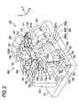
- Fig. 2 illustrates a schematic configuration of the peripheral edge processing part arranged inside the processing apparatus main body 1.
- the lens LE is held by lens chuck shafts (lens rotating shafts) 702L and 702R, and is subjected to the grinding processing by an grindstone group 602 attached to a grindstone rotating shaft 601a rotated by a grindstone rotating motor 601.
- the chuck shafts 702L and 702R and the shaft 601a are arranged in parallel to each other.
- the grindstone group 602 includes a roughing grindstone 602a for glass, a roughing grindstone 602b for plastic, and a finishing grindstone 602c for beveling processing and flatting processing.
- Lens shape measurement parts (units) 500a and 520 described hereinafter are arranged at an upper portion of a carriage portion 700.
- a processing part (unit) 800 for drilling, chamfering and grooving, described hereinafter is arranged at a rear side of the carriage portion 700.
- a lens chuck shaft 702L and a lens chuck shaft 702R are coaxially rotatably retained to a left arm 701L and a right arm 701R of a carriage 700 of the carriage portion 700, respectively.
- a lens chucking motor 710 is fixed to a front portion of the right arm 701R, and the rotation of the motor 710 is transmitted to a pulley 713 through a pulley 711 attached to a rotating shaft of the motor 710 and a belt 712.
- the chuck shaft 702R is moved toward its center axis direction (chuck shaft direction: X-axis direction) through a feeding screw and a nut (not shown) rotatably held inside the right arm 701R, thereby the lens LE is held by the chuck shafts 702L and 702R.
- a lens rotating motor 720 is fixed to a left end portion of the left arm 701L, and the rotation of the motor 720 is transmitted to the chuck shaft 702L through a gear 721 attached to a rotating shaft of the motor 720 and gears 722 through 725.
- the rotation of the motor 720 is also transmitted to the chuck shaft 702R through a rotating shaft 728 rotatably held at a rear side of the carriage 701 and gears at a right end portion of the right arm 701R.
- the chuck shafts 702L and 702R are rotated about the center axis (chuck shaft) in synchronization with each other.
- a movable support base is supported by a carriage shafts 703 and 704 fixed to a base 10 to be slidable in their center axis direction.
- a motor 745 for horizontal movement is fixed to the base 10, and the rotation of the motor 745 is transmitted to the movable support base 740 through a ball screw (not shown) extending in parallel to the shaft 703 at a rear side of the movable support base 740.
- the carriage 701 is moved in a horizontal direction (X-axis direction) together with the movable support base 740.
- the carriage 701 is supported by shafts 756 and 757 which are fixed to the movable support base 740 and extend in a vertical direction (direction which varies an axis-to-axis distance between the chuck shafts 702 and 702R and the shaft 601a: Y-axis direction) to be slidable in their center axis direction.
- a motor 750 for vertical movement is fixed to the movable support base 740 through a plate 751, and the rotation of the motor 750 is transmitted to a ball screw 755 rotatably held by the plate 751 through a pulley 752 attached to a rotating shaft of the motor 750 and a belt 753. Thereby, the ball screw 755 is rotated and the carriage 701 is moved in the vertical direction (Y-axis direction), that is, the axis-to-axis distance between the chuck shafts 702L and 702R varies.
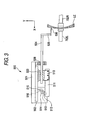
- Fig. 4 is a schematic configuration of the lens shape measurement part (unit) 500 for measuring a front refractive surface shape of the lens LE.
- a support base 501 is fixed to a sub base 100 erected on the base 10 (see fig. 2 ), and a slider 503 is slidably supported on a rail 502 fixed to the support base 501.
- a slide base 510 is fixed to the slider 503, and a feeler arm 504 is fixed to the slide base 510.
- a ball bushing 508 is fitted to a side surface of the support base 501, and has a rattling absorbing function.
- An L-shaped feeler hand 505 is fixed to an distal end of the arm 504 and a disk shape feeler 506 is attached to the distal end of the hand 505.
- the feeler 506 is brought into contact with the front refractive surface of the lens LE.
- a rack 511 is fixed to a lower portion of the slide base 510 and is meshed with a pinion 512 of an encoder 513 fixed to the support base 501.
- a motor 516 is fixed to the support base 501, and the rotation of the motor 516 is transmitted to the rack 511 through a gear 515 attached to the rotating shaft of the motor 516, an idling gear 514 and the pinion 512.
- the slide base 510, the arm 504 and the like are moved in the horizontal direction (X-axis direction).
- the motor 516 always presses the feeler 506 to the lens LE with constant force.
- the encoder 513 detects a travel distance of the slide base 510 (position of the feeler 506) and the like in the horizontal direction.
- the front refractive surface shape of the lens LE is measured on the basis of this travel distance (position) and the rotation angle of the chuck shafts 702L and 702R.
- the description of the structure of a measuring part (unit) 520 for a rear refractive surface shape of the lens LE is omitted since the structure thereof is symmetrical to the structure of the measuring part (unit) 500 for the front refractive surface shape of the lens LE.
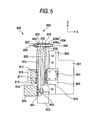
- FIGs. 4 and 5 shows a schematic configuration of the drilling, chamfering and grooving processing part (unit).
- a plate 801 to be a base of the processing part 800 is fixed to the sub base 100.
- a movable support base 804 is fixed to the slider 803, and the movable support base 804 is moved in the cross direction (Z-axis direction) by rotating a ball screw 806 by a motor 805 fixed to the plate 801.
- a rotatable support base 810 is pivotally supported by the movable support base 804 through a bearing 811. At one side of the bearing 811, a gear 813 is fixed to the rotatable support base 810. The gear 813 is communicated with a gear 815 attached to a rotating shaft of a motor 816 fixed to the movable support base 804. That is, the rotatable support base 810 is rotated about an axis of the bearing 811 by the rotation of the motor 816.
- a rotating portion 830 for holding a processing tool for drilling, chamfering and grooving is provided at a distal end of the rotatable support base 810.
- a pulley 832 is attached to a center of a rotating shaft 831 of the rotating portion 830, and the rotating shaft 831 is pivotally supported by two bearings 834.
- An end mill 835 which is a drilling tool is attached to one end of the rotating shaft 831, and a spacer 838 and a grindstone portion 836 are attached to the other end by a nut 839.
- the grindstone portion 836 includes a grindstone 836a for chamfering and a grindstone 836b for grooving.
- a motor 840 for rotating the rotating shaft 831 is fixed to a plate 841 attached to the rotatable support base.
- a pulley 843 is attached to the rotating shaft of the motor 840.
- a belt 833 is laid between the pulley 832 and the pulley 843 inside the rotatable support base 810, and the rotation of the motor 840 is transmitted to the rotating shaft 831.
- two-dimensional target lens shape data is input.
- a template or a dummy lens is measured for shape by the measurement device 2, to obtain the target lens shape data.
- the touch panel 410 displays a figure based on the input target lens shape on the screen thereof so that a user (operator) can input processing conditions.
- layout data e.g. wearer's pupillary distance and optical center height is input.
- a hole-position edit screen is displayed on the touch panel 410 so that the user can input hole-position data.
- Fig. 7 is an example of the hole-position edit screen.
- FC is a geometric center of a target lens shape FT
- Ho1 and Ho2 are two holes, at the nose side, for attaching the rimless frame on the (R) lens for a right eye
- Ho3 and Ho4 are two holes at the ear side.
- the holes Ho1 and Ho2 are assumably formed, side by side, in a direction perpendicular to the front refractive surface (in a direction of a normal line to the front refractive surface) of the lens LE at an intermediate point of the both.
- Hole-position data is usually designated with reference to the geometric center FC, on an orthogonal coordinate system having an x-axis direction taken as a horizontal direction and a y-axis direction as a vertical direction of the eyeglasses.
- Fig. 7 uses an input example to the orthogonal coordinate system. Note that this embodiment uses the x-axis and y-axis directions for managing hole-position data distinctly from the X-axis and Y-axis directions used for the processing apparatus main body 1.
- hole number is designated with a key 411a
- y-axis directional position data is designated with a data input box 412a
- a dimension yc1 of from the geometric center FC is input.
- a data input box 412b is designated, and with using a select key 411b, one out of thee, i.e. a dimension xc1 of from the geometric center FC (center basis), a dimension xh1 of from a lateral edge of the hole H01 (H-edge basis) and a dimension xbl of from an ear-end edge of the target lens shape (B-edge basis) is selected and the dimension is input.
- the dimensions are input by use of a ten key displayed upon pressing the data input boxes 412a, 412b.
- the position data for other hole Ho2 can be similarly input by changing the hole number.
- the dimensions may be input with designating a spacing taken with reference to one of the holes Ho1 and Ho2 as a reference.
- hole-position data may be input by inputting on a polar coordinate system having the geometric center FC as a reference.
- group number is input by a key 416.
- "Auto" is designated by a hole-direction designate key 417, processing can be performed in a direction perpendicular to the front refractive surface at an intermediate point of the holes in the same group. Naturally, it can be at a desired hole-direction.
- a numeral 413 is a data input box for hole diameter data while a numeral 414 is a data input box for hole depth data for forming a counter-bore (non-through hole). Those dimensions are input by a ten key to be displayed upon pressing the data input boxes.
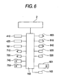
- the hole-position data thus input is stored in the memory 161.
- the hole-position data and the like from an external apparatus is input to a main control section 160 through a communication port 163, and stored in the memory 161.
- the lens LE After completing required input of the hole-position data, etc., the lens LE is held by chuck shafts 702L and 702R. Then, by pressing the processing start switch of the switch portion 420, the apparatus is started up.
- the main control section 160 controls drive of the lens shape measurement parts 500, 520 depending upon the input target lens shape data, to measure the lens LE for its front and back refractive surface shapes. Namely, the main control section 160 drives the motor 516 to move the arm 504 from a retract position into a measurement position.
- the carriage 701 is vertically moved according to the radius vector data of the target lens shape while rotating the lens LE by driving the motor 720. With such rotation and movement of the lens LE, the feeler 506 is moved horizontally along the front refractive surface shape of the lens LE.
- the back refractive surface of the lens LE is also measured for shape data by the lens shape measuring section 520.
- the measured shape data is stored in the memory 161.
- the lens LE is measured for its back refractive surface shape by means of a contour greater than the radial length Rn by ⁇ R in order to determine a curve of back refractive surface of the lens LE.
- the main control section 160 After measuring the shape of the lens LE, the main control section 160 performs a correcting calculation to manage the target lens shape data and the hole-position data in dimensions along the curve of the front refractive surface of the lens LE.
- the correcting calculation is explained in the below.
- shape data Rn, ⁇ n, zn
- the curve Lr is determined from the following equation.
- L ⁇ r R ⁇ i / sin ⁇
- the curve Lr is preferably determined as an average value of the whole refractive surface shape.
- the curve Lr is input to the main control section 160 from the external apparatus (host computer or the like).
- the target lens shape dimensions are corrected into dimensions along the curve Lr.
- the correction is regardless of the coordinate system at the time of input of the hole-position data, and there are a calculation method based on the polar coordinate system and a calculation method based on the orthogonal coordinate system.
- a calculation on the polar coordinate system will be described.
- a radial length Ri and an arc length Rarci are set to be equal to each other.
- the angle ⁇ i for the length Rarci is determined from the following equation.
- a corrected radial length CRi 360 ° ⁇ R ⁇ i / 2 ⁇ ⁇ ⁇ L ⁇ r
- a corrected radial length CRi is determined from the following equation.
- C ⁇ R ⁇ i L ⁇ r ⁇ sin ⁇ ⁇ i
- the main control section 160 manages the input target lens shape dimensions and the input hole-position dimensions in terms of the dimensions along the curve of front refractive surface of the lens LE obtained by the correcting calculation, and determines drilling processing data.
- the drilling processing data can be determined by converting the hole-position data and the hole-direction data into horizontal-directional (X-axis directional) movement data of the carriage 701, vertical-directional (Y-axis directional) movement data thereof, rotation angle data of the lens LE, cross-directional (Z-axis directional) movement data of the processing part 800, rotation angle data of the rotating portion 830 and so on. Meanwhile, the main control section 160 obtains peripheral edge-processing data by determining lens-rotation-based processing points depending upon the corrected target lens shape data.
- a hole direction is determined to be perpendicular to the front refractive surface at an intermediate point of the holes.
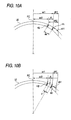
- hole positions are determined such that the hole spacing at an inclination angle of the front refractive surface at the hole intermediate position is equal to a input hole spacing d.
- the two-hole spacing as viewed in a direction along the curve of the front refractive surface is provided equal to the spacing d designated as shown in Fig. 10B , in contrast to the case of the two-hole spacing as shown in Fig. 10A .
- the hole H1 is designated with a dimension xh1 from the lateral edge of the hole H1
- arrangement is possible, without any contradiction, at a position in the dimension xh1 as viewed in the direction along the curve of the front refractive surface similarly to the method to designate a hole-position dimension from the geometric center FC.
- position data of the holes Ho1 and Ho2 is input at different radial angles as in Fig. 7
- the hole positions can be arranged on a three-dimensional lens refractive surface without any contradiction.
- the curve Lr is calculated without positional change.
- the term Rn in equation 5 is replaced into the orthogonal coordinate system value, to calculate x and y corrected coordinates thereof.
- the correction on the orthogonal coordinate system is quite similar to the case of considering a parallel of latitude, representing a position on the earth surface, as an orthographic projection figure (see Fig. 11A ).
- the correction on the polar coordinate system explained before is quite similar to the case of considering a line of longitude, representing a position on the earth surface, as an orthographic projection figure (see Fig. 11B ).
- the correction amount on y-axis coordinate increases as the dimension on x-axis coordinate of from the geometric center FC increases, as shown in Fig. 11B .
- the two holes in the first glance are seen not arranged side by side immediately laterally. However, this is a proper arrangement when viewed in a vertical direction (normal direction) of the lens refractive surface.
- a y-axis coordinate in the polar coordinate system is done on a latitude line Me passing a position Cyc1 on y-axis of the sphere SP.
- the line-of-longitude Me is a curved line if viewed in a zo-axis direction perpendicular to an xy-plane, but it is a straight line when viewed in a za-axis direction passing a position Crysl on y-axis and a spherical center O of the sphere.
- the control section 160 changes the correcting calculation to be applied depending upon an input of a selection signal. Meanwhile, in the case of correction on the orthogonal coordinate system, it may be only on one of the x-axis and y-axis direction. There is less practical problem in making a correction only on the x-axis direction because the hole position on the y-axis direction is usually small in value relative to the geometric center FC.
- the main control section 160 after completing the correcting calculation, performs peripheral edge processing on the lens LE.
- the main control section 160 moves the carriage 701 by the motor 720 such that the lens LE comes to the above of the roughing grindstone 602b, and then vertically moves the carriage 701 by the motor 750 thereby performing roughing processing. Then, the lens LE is moved to a flat portion of the finishing grindstone 602c, to make finishing processing by vertically moving the carriage 701 similarly.
- the corrected radius vector data (CRn, ⁇ n) is smaller than the input radius vector data (Rn, ⁇ n)
- the difference thereof is in a degree practically not problematic for the case with the rimless frame.
- the difference is 0.1 mm or smaller.
- the main control section 160 takes control of movement of the carriage 701 and processing part 800 according to the correction data to the holes Ho1 and Ho2.
- a hole angle ⁇ 2 is previously determined such that the intermediate point of the two holes is perpendicular to the lens refractive surface (see Fig. 14 ).
- the main control section 160 inclines the rotation axis of the end mill 835 by the angle ⁇ 2 relative to the horizontal direction (X-axis direction), and controls the rotation of the lens LE and the movement in the horizontal direction (X-axis direction) and the vertical direction (Y-axis direction) of the carriage 701, thereby placing the distal end of the end mill 835 in the corrected hole position. Thereafter, the end mill 835 is rotated by the motor 840, to move the carriage 701 axially (in a direction of the angle ⁇ 2) of the rotation axis of the end mill 835, thereby forming a hole. Another hole is made similarly by placing the distal end of the end mill 835 in the corrected hole position while maintaining the angle ⁇ 2. This makes it possible to form holes on the three-dimensional refractive surface according to the positions designated on the two-dimensional coordinate system without any contradiction.
- Drilling processing is available in a desired direction relative to the lens refractive surface.
- a menu screen is displayed by a angle designate key 417 of Fig. 7 , to designate a desired angle on the screen displayed.
- the main control section 160 determines the axial direction of the end mill 835, the rotation angle of the lens LE and the cross-directional (Z-axis direction) position of the rotating portion 830 based on the designated angle.
- the drilling processing is performed by moving the carriage 701 in the XY directions.
- the drilling processing control is basically identical to that of U.S. Pat. 6,790,124 ( JP-A-2003-145328 ), and omitted to explain in detail.
- the lens LE may be a monofocal lens or a progressive power lens.
- the front refractive surface differs in curve from point to point.
- there is less practical error if determining an average value over refractive surface process measured the lens shape throughout the entire circumference.
- the apparatus of the type that the carriage 701, having the chuck shaft that clamps and rotates the lens LE, is moved in the horizontal direction (X-axis direction) and in the vertical direction (Y-axis direction) is employed.
- it may be in a structure to move the rotating portion 830 (end mill 835) in three-dimensional directions.
Landscapes
- Engineering & Computer Science (AREA)
- Mechanical Engineering (AREA)
- Chemical & Material Sciences (AREA)
- Ceramic Engineering (AREA)
- Inorganic Chemistry (AREA)
- Mining & Mineral Resources (AREA)
- Eyeglasses (AREA)
- Grinding And Polishing Of Tertiary Curved Surfaces And Surfaces With Complex Shapes (AREA)
- Drilling And Boring (AREA)
Applications Claiming Priority (1)
| Application Number | Priority Date | Filing Date | Title |
|---|---|---|---|
| JP2005001891A JP4708035B2 (ja) | 2005-01-06 | 2005-01-06 | 眼鏡レンズ加工装置 |
Publications (2)
| Publication Number | Publication Date |
|---|---|
| EP1679153A1 EP1679153A1 (en) | 2006-07-12 |
| EP1679153B1 true EP1679153B1 (en) | 2010-06-02 |
Family
ID=35782287
Family Applications (1)
| Application Number | Title | Priority Date | Filing Date |
|---|---|---|---|
| EP06000336A Not-in-force EP1679153B1 (en) | 2005-01-06 | 2006-01-09 | Eyeglass lens processing apparatus |
Country Status (5)
| Country | Link |
|---|---|
| US (1) | US7507142B2 (enExample) |
| EP (1) | EP1679153B1 (enExample) |
| JP (1) | JP4708035B2 (enExample) |
| DE (1) | DE602006014605D1 (enExample) |
| ES (1) | ES2344990T3 (enExample) |
Families Citing this family (16)
| Publication number | Priority date | Publication date | Assignee | Title |
|---|---|---|---|---|
| JP4841269B2 (ja) | 2006-02-28 | 2011-12-21 | 株式会社ニデック | 眼鏡レンズ加工装置 |
| JP4749892B2 (ja) * | 2006-02-28 | 2011-08-17 | 株式会社ニデック | 穴データ入力装置及びこれを備える眼鏡レンズ加工装置 |
| JP5085898B2 (ja) * | 2006-07-31 | 2012-11-28 | 株式会社ニデック | 眼鏡レンズ加工装置 |
| JP5065645B2 (ja) * | 2006-09-29 | 2012-11-07 | 株式会社ニデック | 眼鏡レンズ加工方法及び眼鏡レンズ加工システム |
| US7970487B2 (en) * | 2006-11-30 | 2011-06-28 | National Optronics, Inc. | Method of calibrating an ophthalmic processing device, machine programmed therefor, and computer program |
| FR2910644B1 (fr) * | 2006-12-20 | 2009-02-27 | Essilor Int | Dispositif de determination de la position et/ou d'une dimension transversale d'un trou de percage d'une lentille de presentation de lunettes a monture sans cercle |
| FR2910646B1 (fr) * | 2006-12-20 | 2009-02-27 | Essilor Int | Procede de determination de la position d'un trou de percage a realiser sur une lentille ophtalmique |
| JP4975469B2 (ja) | 2007-02-02 | 2012-07-11 | 株式会社ニデック | 眼鏡レンズ加工装置 |
| JP5356082B2 (ja) * | 2009-03-26 | 2013-12-04 | 株式会社ニデック | 眼鏡レンズ加工装置 |
| FR3002871B1 (fr) * | 2013-03-08 | 2015-03-13 | Essilor Int | Dispositif de detourage de lentilles ophtalmiques |
| JP6446176B2 (ja) * | 2013-11-11 | 2018-12-26 | 株式会社ニコン・エシロール | 眼鏡レンズ製造システム及び眼鏡レンズ製造方法 |
| JP6652002B2 (ja) * | 2016-07-01 | 2020-02-19 | 株式会社ニデック | 眼鏡レンズ加工装置および加工制御データ作成プログラム |
| JP6690438B2 (ja) * | 2016-07-01 | 2020-04-28 | 株式会社ニデック | 眼鏡レンズ加工装置および加工制御データ作成プログラム |
| KR102344250B1 (ko) | 2016-07-01 | 2021-12-27 | 가부시키가이샤 니데크 | 안경 렌즈 가공 장치 및 가공 제어 데이터 작성 프로그램 |
| CN109530753B (zh) * | 2019-01-21 | 2023-08-29 | 天津普天单向器有限公司 | 一种倒角加工组合装置及使用方法 |
| JP7331536B2 (ja) * | 2019-07-31 | 2023-08-23 | 株式会社ニデック | 眼鏡レンズの穴データ入力装置、穴データ入力プログラム及び穴データ入力方法 |
Family Cites Families (14)
| Publication number | Priority date | Publication date | Assignee | Title |
|---|---|---|---|---|
| JPH02274408A (ja) * | 1989-04-11 | 1990-11-08 | Mikhailov Hodosevich Vladimir | 算定された空隙を有する対物レンズのレンズホールダの穿孔作業法 |
| JPH0313377A (ja) * | 1989-06-12 | 1991-01-22 | Fuji Photo Film Co Ltd | 記録材料 |
| JPH04269149A (ja) * | 1991-02-20 | 1992-09-25 | Toshiba Corp | 穴加工用ncデータ作成方法 |
| JP3011526B2 (ja) * | 1992-02-04 | 2000-02-21 | 株式会社ニデック | レンズ周縁加工機及びレンズ周縁加工方法 |
| JP3602175B2 (ja) * | 1994-12-09 | 2004-12-15 | 株式会社トプコン | リムレスレンズ用穴開け装置とこれを用いた玉摺機とこの玉摺機に使用されるメガネ用形状測定装置 |
| JP3000211B2 (ja) * | 1997-12-12 | 2000-01-17 | 株式会社 三共社 | メガネレンズにテンプル、ブリッジを取り付ける取付方法 |
| DE19804428A1 (de) * | 1998-02-05 | 1999-08-19 | Wernicke & Co Gmbh | Verfahren zum Markieren oder Bohren von Löchern in Brillengläsern und Vorrichtung zur Durchführung des Verfahrens |
| JP2000105356A (ja) * | 1998-04-28 | 2000-04-11 | Vision Megane:Kk | メガネのレンズ取付構造 |
| JP2000111842A (ja) * | 1998-09-30 | 2000-04-21 | Pentax Vision Kk | 縁無し眼鏡レンズ用穴開け治具 |
| JP3695988B2 (ja) * | 1999-04-30 | 2005-09-14 | 株式会社ニデック | 眼鏡枠形状測定装置 |
| JP4194192B2 (ja) | 1999-10-07 | 2008-12-10 | 株式会社ニデック | 玉型形状測定装置 |
| JP3916445B2 (ja) | 2001-11-08 | 2007-05-16 | 株式会社ニデック | 眼鏡レンズ加工装置 |
| JP2004009201A (ja) | 2002-06-06 | 2004-01-15 | Toshiba Corp | リムレスレンズ用穴開け加工装置およびこれを用いたレンズ研削加工装置 |
| JP4098046B2 (ja) * | 2002-09-20 | 2008-06-11 | 株式会社トプコン | レンズ研削加工装置 |
-
2005
- 2005-01-06 JP JP2005001891A patent/JP4708035B2/ja not_active Expired - Fee Related
-
2006
- 2006-01-06 US US11/326,332 patent/US7507142B2/en not_active Expired - Fee Related
- 2006-01-09 DE DE602006014605T patent/DE602006014605D1/de active Active
- 2006-01-09 ES ES06000336T patent/ES2344990T3/es active Active
- 2006-01-09 EP EP06000336A patent/EP1679153B1/en not_active Not-in-force
Also Published As
| Publication number | Publication date |
|---|---|
| EP1679153A1 (en) | 2006-07-12 |
| ES2344990T3 (es) | 2010-09-13 |
| US7507142B2 (en) | 2009-03-24 |
| DE602006014605D1 (de) | 2010-07-15 |
| JP4708035B2 (ja) | 2011-06-22 |
| US20060178086A1 (en) | 2006-08-10 |
| JP2006189659A (ja) | 2006-07-20 |
Similar Documents
| Publication | Publication Date | Title |
|---|---|---|
| JP3916445B2 (ja) | 眼鏡レンズ加工装置 | |
| EP1679153B1 (en) | Eyeglass lens processing apparatus | |
| EP1310326B1 (en) | Eyeglass lens processing apparatus | |
| KR101403181B1 (ko) | 구멍 데이터 입력 장치 및 이를 갖는 안경 렌즈 가공 장치 | |
| US7611243B2 (en) | Eyeglass lens processing method | |
| US8366512B2 (en) | Eyeglass lens processing apparatus for processing periphery of eyeglass lens and eyeglass lens processing method | |
| US7840294B2 (en) | Layout setting device for processing eyeglass lens, eyeglass lens processing apparatus, eyeglass frame measuring device and cup attaching device, each having the same | |
| US7617579B2 (en) | Eyeglass lens processing apparatus | |
| EP2106879B1 (en) | Eyeglass lens processing apparatus | |
| US20080186446A1 (en) | Eyeglass lens processing apparatus | |
| US20020045403A1 (en) | Spectacle lens chamfering data preparing method, spectacle lens chamfering method, spectacle lens chamfering data preparing apparatus, and spectacle lens chamfering apparatus | |
| KR101437160B1 (ko) | 안경 렌즈 가공 장치 | |
| KR101383458B1 (ko) | 안경 렌즈 가공 장치 | |
| KR101415449B1 (ko) | 파셋 가공 영역 설정 장치 및 이것을 갖는 안경 렌즈 가공장치 | |
| JP4781973B2 (ja) | 眼鏡レンズ加工装置 |
Legal Events
| Date | Code | Title | Description |
|---|---|---|---|
| PUAI | Public reference made under article 153(3) epc to a published international application that has entered the european phase |
Free format text: ORIGINAL CODE: 0009012 |
|
| AK | Designated contracting states |
Kind code of ref document: A1 Designated state(s): AT BE BG CH CY CZ DE DK EE ES FI FR GB GR HU IE IS IT LI LT LU LV MC NL PL PT RO SE SI SK TR |
|
| AX | Request for extension of the european patent |
Extension state: AL BA HR MK YU |
|
| 17P | Request for examination filed |
Effective date: 20061228 |
|
| AKX | Designation fees paid |
Designated state(s): DE ES FR GB |
|
| 17Q | First examination report despatched |
Effective date: 20070611 |
|
| GRAP | Despatch of communication of intention to grant a patent |
Free format text: ORIGINAL CODE: EPIDOSNIGR1 |
|
| GRAS | Grant fee paid |
Free format text: ORIGINAL CODE: EPIDOSNIGR3 |
|
| GRAA | (expected) grant |
Free format text: ORIGINAL CODE: 0009210 |
|
| AK | Designated contracting states |
Kind code of ref document: B1 Designated state(s): DE ES FR GB |
|
| REG | Reference to a national code |
Ref country code: GB Ref legal event code: FG4D |
|
| REF | Corresponds to: |
Ref document number: 602006014605 Country of ref document: DE Date of ref document: 20100715 Kind code of ref document: P |
|
| REG | Reference to a national code |
Ref country code: ES Ref legal event code: FG2A Ref document number: 2344990 Country of ref document: ES Kind code of ref document: T3 |
|
| PLBE | No opposition filed within time limit |
Free format text: ORIGINAL CODE: 0009261 |
|
| STAA | Information on the status of an ep patent application or granted ep patent |
Free format text: STATUS: NO OPPOSITION FILED WITHIN TIME LIMIT |
|
| 26N | No opposition filed |
Effective date: 20110303 |
|
| REG | Reference to a national code |
Ref country code: DE Ref legal event code: R097 Ref document number: 602006014605 Country of ref document: DE Effective date: 20110302 |
|
| REG | Reference to a national code |
Ref country code: FR Ref legal event code: PLFP Year of fee payment: 11 |
|
| PGFP | Annual fee paid to national office [announced via postgrant information from national office to epo] |
Ref country code: ES Payment date: 20151214 Year of fee payment: 11 |
|
| PGFP | Annual fee paid to national office [announced via postgrant information from national office to epo] |
Ref country code: GB Payment date: 20160106 Year of fee payment: 11 |
|
| REG | Reference to a national code |
Ref country code: FR Ref legal event code: PLFP Year of fee payment: 12 |
|
| GBPC | Gb: european patent ceased through non-payment of renewal fee |
Effective date: 20170109 |
|
| PG25 | Lapsed in a contracting state [announced via postgrant information from national office to epo] |
Ref country code: GB Free format text: LAPSE BECAUSE OF NON-PAYMENT OF DUE FEES Effective date: 20170109 |
|
| REG | Reference to a national code |
Ref country code: FR Ref legal event code: PLFP Year of fee payment: 13 |
|
| PGFP | Annual fee paid to national office [announced via postgrant information from national office to epo] |
Ref country code: FR Payment date: 20171211 Year of fee payment: 13 |
|
| PGFP | Annual fee paid to national office [announced via postgrant information from national office to epo] |
Ref country code: DE Payment date: 20171228 Year of fee payment: 13 |
|
| PG25 | Lapsed in a contracting state [announced via postgrant information from national office to epo] |
Ref country code: ES Free format text: LAPSE BECAUSE OF NON-PAYMENT OF DUE FEES Effective date: 20170110 |
|
| REG | Reference to a national code |
Ref country code: ES Ref legal event code: FD2A Effective date: 20180625 |
|
| REG | Reference to a national code |
Ref country code: DE Ref legal event code: R119 Ref document number: 602006014605 Country of ref document: DE |
|
| PG25 | Lapsed in a contracting state [announced via postgrant information from national office to epo] |
Ref country code: FR Free format text: LAPSE BECAUSE OF NON-PAYMENT OF DUE FEES Effective date: 20190131 Ref country code: DE Free format text: LAPSE BECAUSE OF NON-PAYMENT OF DUE FEES Effective date: 20190801 |