EP1673000B1 - Lave-vaisselle a canaux de pulverisation integres - Google Patents
Lave-vaisselle a canaux de pulverisation integres Download PDFInfo
- Publication number
- EP1673000B1 EP1673000B1 EP04765895.0A EP04765895A EP1673000B1 EP 1673000 B1 EP1673000 B1 EP 1673000B1 EP 04765895 A EP04765895 A EP 04765895A EP 1673000 B1 EP1673000 B1 EP 1673000B1
- Authority
- EP
- European Patent Office
- Prior art keywords
- dishwasher
- spray channel
- spray
- cavity
- interior
- Prior art date
- Legal status (The legal status is an assumption and is not a legal conclusion. Google has not performed a legal analysis and makes no representation as to the accuracy of the status listed.)
- Not-in-force
Links
- 239000007921 spray Substances 0.000 title claims description 137
- 238000005406 washing Methods 0.000 claims description 87
- 239000007788 liquid Substances 0.000 claims description 48
- 238000005507 spraying Methods 0.000 claims description 23
- 238000009826 distribution Methods 0.000 claims description 12
- 230000033001 locomotion Effects 0.000 description 5
- 238000011010 flushing procedure Methods 0.000 description 4
- 239000012530 fluid Substances 0.000 description 3
- 238000004140 cleaning Methods 0.000 description 2
- 238000004519 manufacturing process Methods 0.000 description 2
- 238000002360 preparation method Methods 0.000 description 2
- 238000011161 development Methods 0.000 description 1
- 230000018109 developmental process Effects 0.000 description 1
- 238000004851 dishwashing Methods 0.000 description 1
- 230000000694 effects Effects 0.000 description 1
- 239000013013 elastic material Substances 0.000 description 1
- 230000002262 irrigation Effects 0.000 description 1
- 238000003973 irrigation Methods 0.000 description 1
- 238000005086 pumping Methods 0.000 description 1
- 239000013589 supplement Substances 0.000 description 1
- 230000002123 temporal effect Effects 0.000 description 1
- 230000000007 visual effect Effects 0.000 description 1
- XLYOFNOQVPJJNP-UHFFFAOYSA-N water Substances O XLYOFNOQVPJJNP-UHFFFAOYSA-N 0.000 description 1
Images


Classifications
-
- A—HUMAN NECESSITIES
- A47—FURNITURE; DOMESTIC ARTICLES OR APPLIANCES; COFFEE MILLS; SPICE MILLS; SUCTION CLEANERS IN GENERAL
- A47L—DOMESTIC WASHING OR CLEANING; SUCTION CLEANERS IN GENERAL
- A47L15/00—Washing or rinsing machines for crockery or tableware
- A47L15/14—Washing or rinsing machines for crockery or tableware with stationary crockery baskets and spraying devices within the cleaning chamber
- A47L15/16—Washing or rinsing machines for crockery or tableware with stationary crockery baskets and spraying devices within the cleaning chamber with rigidly-mounted spraying devices
Definitions
- the invention relates to a dishwasher with one or more washing containers and a device for spraying arranged in the washing container items.
- rotating spray arms There are dishwasher with sprayers are known to work with rotating spray arms.
- the washing container usually has a rectangular outline
- the rotating spray arms have a circular area of action
- the respective corner areas can only be insufficiently sprayed with flushing liquid by the rotating spray arms.
- rotating spray arms have the disadvantage that they are moving parts, which are subject to both the movement-related wear and an increased susceptibility to interference when, for example, advised in the range of movement of the spray arm wash prevents the rotation of the spray arm.
- dishwashers with spray devices are known in which rinsing liquid is applied to the items to be washed in the washing container via fixed spray nozzles or spray nozzles.
- Such spraying devices have the disadvantage that they protrude into the interior of the washing and the exiting spray has a predetermined direction, so that a uniform cleaning effect of the dishes can not be guaranteed.
- a dishwasher which has a rinsing liquid leading spray channel, which is integrated in the bottom region of the washing container and on a side facing the interior of the washing container has openings for the passage of the rinsing liquid.
- a dishwashing machine which has a flushing liquid leading spray channel, which is integrated in the wall region of the washing container and has at least one spray nozzle for the passage of the washing liquid on a side directed towards the interior of the washing container.
- Dishwasher which has a flushing liquid leading spray channel, which is integrated in the ceiling region of the washing and has on a side facing the interior of the washing container openings for the passage of the washing liquid.
- a device for the automatic cleaning of dishes wherein the dishes used in the device is sprayed with water and wherein the intensity of the spray action is adjustable or switchable.
- the intensity of the spray action is adjustable or switchable.
- the number of nozzles used for the normal case is reduced adjustable.
- Object of the present invention is to provide a dishwasher with a space-saving device for spraying ware, in which the rinsing liquid is sprayed as evenly as possible in the washing to flush the wash ware efficiently, and eliminates the conditional by moving parts wear and susceptibility becomes.
- the dishwasher according to the invention comprises at least one rinsing container and a spraying device for spraying rinsing liquid into the interior of the rinsing container, wherein the spraying device has at least one rinsing liquid-carrying spray channel, which is integrated in the floor, ceiling and / or wall region of the rinsing container and on the interior
- the flushing container side has openings for the passage of the rinsing liquid.
- One advantage of the dishwasher with a spraying device according to the present invention is, on the one hand, that the uniform spray distribution of the rinsing liquid in the rinsing container is improved by the spray channel integrated in the base, ceiling or wall region of the rinsing container.
- the dishwasher according to the invention for the administration and distribution of the rinsing liquid no moving components, such as e.g. Spray arms, required and thereby also a movement-related wear or the susceptibility of moving parts eliminated. This has the consequence that, for example, falling crockery parts no longer disturb the spray distribution of the rinsing liquid, since no more mechanically moving parts are present, which could be hindered in their range of motion.
- the usable space for the arrangement of items to be washed in the washing is increased.
- the crockery parts can be placed extremely close to the bottom, ceiling or wall area of the washing container, since no more freedom of movement for a rotating spray arm has to be taken into account.
- the freedom in the design of the dish racks located in the rinsing container is greater because no rotating spray arms or from the bottom, ceiling or wall portions of the rinse tank protruding components for distributing the rinsing liquid are more to be considered.
- Yet another advantage of the spraying device of the dishwasher according to the invention is that the length and width of the washing container need not necessarily be formed in a ratio of at least almost 1: 1 - as required for example in a spraying device with rotating spray arms - but in almost can be designed in any shape, since the integrated in the bottom, ceiling and / or wall area of the washing container spray channels each shape of the Rinse container can be adjusted accordingly.
- the shape and / or the number of openings for the passage of the rinsing liquid are preferably determined such that the desired rinsing is achieved in the interior of the rinsing container. In this case, the most uniform possible spray distribution or even a non-uniform spray distribution can be sought, in which certain areas are rinsed in the washing more than others.
- the at least one spray channel is tube-like and preferably has two open ends, can be supplied pressurized via the rinsing liquid.
- irrigation fluid can be fed under pressure to both ends of the tubular spray channel independently of one another.
- the supply of the rinsing liquid to the spray channel by a pumping device, such. the circulating pump of the dishwasher accomplished.
- the pressure with which the rinsing liquid is supplied to the spray channel via its one end or via its two ends can be varied. That is, either the pressure for the supply of rinsing liquid can be varied only via one end of the spray channel or the pressure for the supply of rinsing liquid over both ends of the spray channel.
- the supply of rinsing liquid to the spray channel with temporally variable pressure allows the generation of spray patterns, which can be adapted for example to specific items to be washed.
- the spray patterns are caused by the different pressure distribution of the rinsing liquid in the spray channel, which results from the temporal variation of the pressure with which the supply of rinsing liquid is made via the two ends of the spray channel, wherein the liquid pressure generated at one end of the spray channel to the the fluid pressure generated at the other end of the spray channel is different.
- differently strong jets of rinsing liquid with different pressure emerge from the openings of the spray channel into the interior of the rinsing container. Due to the different Druckbeanschlagung at the ends of Sprühkanales the maximum pressure in Sprühkananl, ie the place along the channel, in which the exiting beam its max. Momentum possesses to be varied.
- the variation of the pressure with which the rinsing liquid is supplied to the spray channel can be controlled by a pressure distribution with electronic, hydraulic or mechanical means.
- the use of an electronically controlled pressure distribution has the advantage that in turn no rotating or moving components are required, since both the spray intensity and the spray pattern is carried out via a controlled pressure and pressure control.
- a plurality of different spray patterns can be generated in accordance with a wash program selection. When selecting the spray patterns, it is possible to take into account the different soiling conditions and the type of items to be washed.
- the directed to the interior of the washing container side of the spray is substantially in a plane with the directed to the interior of the Spül actuallyers bottom, ceiling or wall surface of the washing, in which the spray channel is integrated.
- the spray channel preferably has a round, preferably circular cross-section.
- the hydraulic losses can be kept small.
- the spray channel is designed to be manually detachable from the floor, ceiling or wall region of the washing container and can preferably be fixed via a clamping connection in the floor, ceiling and / or wall region of the washing container.
- the spray channel can be removed if necessary from the washing, for example, to rid it of deposits. But it can also be replaced by another spray channel with different openings for the escape of rinsing liquid to a to obtain different spray pattern.
- a wall of the spray channel directed toward the interior of the washing container may be designed to be detachable by hand, the side being preferably fixable on the spray channel via a clamping connection in the base, ceiling and / or wall region of the washing container.
- the removable side of the spray channel allows it to be removed like a lid from the spray channel to gain access to the interior of the spray channel. It is particularly useful if the removable side of the spray channel is also the side which has the openings for the passage of the rinsing liquid from the spray channel into the interior of the washing compartment. Thereby, if necessary, only the cover of the spray channel can be removed, for example, to clear the openings of deposits, to inspect the interior of the spray channel or to replace it with another cover.
- the side of the spray channel directed towards the interior of the washing container may also be formed by the ceiling, the wall and / or the bottom of the washing container, wherein the ceiling, the wall and / or the bottom in the region of the spray channel, the openings for the passage of the washing liquid exhibit.
- at least the directed to the interior of the washing container side of the spray channel and the ceiling, the wall and / or the bottom of the washing container is integrally formed. Since the rinsing containers are usually made of plastic, the openings for the passage of the rinsing liquid can either be introduced subsequently or already provided during the production of the rinsing container.
- the entire spray channel with the ceiling, the wall and / or the bottom of the washing can be formed in one piece and already provided during the preparation of the washing.
- the washing container is formed like a tub, and at least in the bottom of the washing container a number of preferably parallel aligned spray channels is integrated.
- the number of spray channels depends on the volume of the washing container or on the surface of the dishwasher base. The establishment of several spray channels promotes a uniform spray distribution of the rinsing liquid in the washing and prevents the "Shutdown" of spray through the dishes.
- the bottom of the washing container can be shaped such that the spray channels are at different levels and thus a plurality of spray levels are formed.
- FIG. 1 shows a part of the washing container 1 of a dishwasher with a spraying device according to a first embodiment of the present invention.
- a part of the bottom 2 of the washing container 1 is shown, in which a recess 3 is provided in the form of a groove.
- a removable cover 7 is arranged, which covers the recess 3 over its entire length.
- the recess 3 thus provides in cooperation with the cover 7 is a spray channel 4, which is supplied during operation, for example via the circulation pump rinsing liquid.
- openings 9 are provided for the passage of the rinsing liquid from the spray channel 4 in the interior of the washing compartment 1.
- the cover 7 has a symmetrical and substantially U-shaped cross section, wherein the two free ends of the U-shaped cross section are formed by legs 8.
- the cover 7 is made of an elastic material, so that the legs 8 can be flexibly bent against each other against a bias. In this way, a clamping connection is formed between the legs 8 and the side wall 6 of the spray channel 4, whereby the cover 7 is fixed in the bottom 2 of the washing container 1 on the spray channel 4.
- the removable cover 7 of the spray channel 4 makes it possible to remove it as needed from the spray channel 4 as a cover, for example, to inspect the interior of the spray channel 4 and free of deposits or attach another cover 7.
- FIG. 2 shows a second partial sectional view of the bottom 2 of the washing container 1 of a dishwasher with a spraying device according to the in FIG. 1 illustrated embodiment.
- the recess 3 in the bottom 2 of the washing compartment 1 is a spray channel 4, which is completed by the cover 7 to the interior of the washing compartment 1.
- the cover is fixed via the clamping connection between the two legs 8 and the side walls 6 of the spray channel 4.
- openings 9 for the passage of the rinsing liquid from the spray channel 4 in the interior of the washing container. 1
- FIG. 2 It can clearly be seen that the cover 7 and thus the interior of the washing container 1 directed side of the spray channel is substantially in a plane with the bottom 2 of the washing compartment 1. This results in a flat surface over the entire bottom 2 of the washing container 1, which allows a largely arbitrary arrangement of items to be washed 10 in the immediate vicinity of the bottom 2 of the washing compartment 1. Since the openings 7 are distributed over the entire length of the spray channel 4, the possibility of "shadowing" of spray jets 10 is reduced. Even with direct support of the dishes 10 on the spray 4 can be due to the elongated Shape of the opening 9 still rinsing liquid from the spray channel 4 are sprayed into the washing 1.
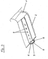
- FIG. 3 shows a partial sectional view of the bottom 2 of the washing container 1 of a dishwasher with a spraying device according to a second embodiment of the present invention.
- the spray channel 5 is formed closed, wherein the interior of the washing container 1 facing side of the spray channel 5 has openings 9 for the passage of the rinsing liquid.
- the spray channel 5 is further designed so that it is manually detachable from the bottom 2 of the washing container 1 and can be fixed again via a clamping connection. This makes it possible to remove the spray channel 5, if necessary, from the washing container 1, for example, to free it of deposits or to replace it with another spray channel 5.
- the spray channel 4 has a substantially rectangular, nearly square cross-section.
- the spray channel 5 has a trapezoidal cross section, with the distance between the side walls 6 of the spray channel 5 tapering from the side of the spray channel 5 facing the interior of the washing container 1 to the side of the spray channel 5 facing away from the interior of the washing container 1.
- such a spray channel can also be provided with a round or at least partially round, preferably circular cross-section. This, although more complicated to manufacture, would improve the hydronic parameters.
- FIG. 4 shows a partial sectional view of the bottom 2 of the washing compartment 1 of a dishwasher with a spraying device according to a third embodiment of the present invention.
- the direction of the interior of the washing container 1 side of the spray channel 4 is formed by the bottom 2 of the washing container 1, wherein the bottom 2 in the region of the spray channel 4 has openings 9 for the passage of the washing liquid.
- the remaining walls of the spray channel 4 and thus the spray channel 4 may be formed integrally with the bottom 2 of the washing container 1, wherein the openings 9 for the passage of the Rinsing fluid either introduced later or already provided during the preparation of the washing compartment 1.
- FIG. 5 shows a partial sectional view of the bottom 2 of the washing container 1 of a dishwasher with a spraying device according to a fourth embodiment of the present invention.
- the design of the spray channels 4 substantially corresponds to that in the FIGS. 1 and 2 illustrated embodiment.
- the washing container 1 is formed like a trough, wherein in the bottom 2 of the washing container 1, a number of preferably parallel aligned recesses is provided, which are provided with covers 7.
- the number of spray channels 4 should be adapted to the volume of the washing container 1 or to the surface of the dishwasher base 2.
- the bottom 2 of the washing container 1 is shaped in such a way that the spray channels 4 lie on different levels and thus a plurality of spray levels are formed.
- the provision of several spray channels 4, 5 favors a uniform spray distribution of the rinsing liquid in the rinsing tank 1, which is further improved by the arrangement of the spray channels 4 at different heights.
Claims (11)
- Lave-vaisselle avec au moins une cuve de lavage (1) et un dispositif de pulvérisation afin de pulvériser du liquide de lavage dans l'espace intérieur de la cuve de lavage (1) dans lequel le dispositif de pulvérisation englobe au moins un canal de pulvérisation (4, 5) servant à transporter le liquide de lavage et intégré dans le sol, le dessus et/ou la paroi de la cuve de lavage (1) et présente sur un côté (7) dirigé vers l'espace intérieur de la cuve de lavage (1) des orifices (9) pour la traversée de liquide de lavage, caractérisé en ce que le canal de pulvérisation (4, 5) est exécuté de sorte à pouvoir être désolidarisé manuellement du sol, du dessus ou de la paroi de la cuve de lavage (1).
- Lave-vaisselle selon la revendication 1, dans lequel le canal de pulvérisation (4, 5) est exécuté sous la forme d'un tuyau et présente de préférence deux extrémités ouvertes via lesquelles du liquide de lavage sous pression peut être injecté.
- Lave-vaisselle selon l'une des revendications précédentes, dans lequel la pression à laquelle le liquide de lavage est amené dans le canal de pulvérisation (4, 5) est variable.
- Lave-vaisselle selon la revendication 3, dans lequel la variation de la pression à laquelle le liquide de lavage est amené dans le canal de pulvérisation (4, 5) est pilotée via une répartition de pression avec des moyens électroniques, hydrauliques et/ou mécaniques.
- Lave-vaisselle selon l'une des revendications précédentes, dans lequel le côté du canal de pulvérisation (4, 5) dirigé vers l'espace intérieur de la cuve de lavage (1) se trouve essentiellement dans le même plan que le sol, le dessus et le côté de la cuve de lavage (1) dirigé vers l'espace intérieur de la cuve de lavage (1) dans lequel le canal de pulvérisation (4, 5) est intégré.
- Lave-vaisselle selon l'une des revendications précédentes, caractérisé en ce que le canal de pulvérisation (4, 5) présente une section ronde, de préférence circulaire.
- Lave-vaisselle selon l'une des revendications précédentes, dans lequel le canal de pulvérisation (4, 5) présente une section rectangulaire, de préférence essentiellement quadratique.
- Lave-vaisselle selon l'une des revendications précédentes, dans lequel le canal de pulvérisation (4, 5) peut être fixé dans le sol, le dessus et/ou la paroi de la cuve de lavage (1) via un accouplement de serrage.
- Lave-vaisselle selon l'une des revendications précédentes, dans lequel une paroi (7) du canal de pulvérisation (4, 5) dirigée vers l'espace intérieur de la cuve de lavage (1) est exécutée de sorte à pouvoir être désolidarisée manuellement et fixée sur le canal de pulvérisation (4, 5) de préférence via un accouplement de serrage (6) dans le sol, le dessus ou la paroi de la cuve de lavage (1).
- Lave-vaisselle selon l'une des revendications précédentes, dans lequel la paroi (7) du canal de pulvérisation (4, 5) dirigée vers l'espace intérieur de la cuve de lavage (1) est exécutée à travers le dessus, la paroi et/ou le sol (2) de la cuve de lavage (1), le dessus, la paroi et/ou le sol (2) présentant des orifices (7) pour la traversée de liquide de lavage au niveau du canal de pulvérisation (4, 5).
- Lave-vaisselle selon l'une des revendications précédentes, dans lequel la cuve de lavage (1) est exécutée sous la forme d'une cuvette et dans lequel un nombre de canaux de pulvérisation (4, 5) de préférence disposés parallèlement les uns aux autres sont au moins intégrés dans le sol (2) de la cuve de lavage (1).
Applications Claiming Priority (2)
| Application Number | Priority Date | Filing Date | Title |
|---|---|---|---|
| DE10346676A DE10346676A1 (de) | 2003-10-08 | 2003-10-08 | Geschirrspüler mit integrierten Sprühkanälen |
| PCT/EP2004/011270 WO2005034712A1 (fr) | 2003-10-08 | 2004-10-08 | Lave-vaisselle a canaux de pulverisation integres |
Publications (2)
| Publication Number | Publication Date |
|---|---|
| EP1673000A1 EP1673000A1 (fr) | 2006-06-28 |
| EP1673000B1 true EP1673000B1 (fr) | 2013-06-05 |
Family
ID=34399353
Family Applications (1)
| Application Number | Title | Priority Date | Filing Date |
|---|---|---|---|
| EP04765895.0A Not-in-force EP1673000B1 (fr) | 2003-10-08 | 2004-10-08 | Lave-vaisselle a canaux de pulverisation integres |
Country Status (6)
| Country | Link |
|---|---|
| US (1) | US7887642B2 (fr) |
| EP (1) | EP1673000B1 (fr) |
| CN (1) | CN100591260C (fr) |
| DE (1) | DE10346676A1 (fr) |
| NZ (1) | NZ546281A (fr) |
| WO (1) | WO2005034712A1 (fr) |
Families Citing this family (9)
| Publication number | Priority date | Publication date | Assignee | Title |
|---|---|---|---|---|
| WO2005060813A1 (fr) * | 2003-12-22 | 2005-07-07 | BSH Bosch und Siemens Hausgeräte GmbH | Lave-vaisselle a buses de pulverisation fixes |
| ATE413524T1 (de) | 2006-03-02 | 2008-11-15 | Fiat Ricerche | Brennkraftmaschine mit mitteln zur bestimmung frischluftmasse, und dazugehörige methode zur bestimmung |
| US20120111376A1 (en) * | 2010-11-08 | 2012-05-10 | Worrasangasilpa Brian | Device for pre-rinsing objects in an appliance utilizing line pressure of a fluid supply |
| DE102012202246B4 (de) | 2012-02-15 | 2024-02-08 | BSH Hausgeräte GmbH | Geschirrspülmaschine mit einer Sprüheinrichtung |
| US9155447B2 (en) | 2012-11-13 | 2015-10-13 | Whirlpool Corporation | Dish rack with integral hydraulic circuit |
| US9713414B2 (en) | 2013-06-21 | 2017-07-25 | Whirlpool Corporation | Dishwasher having a conduit framework |
| US9895043B2 (en) | 2015-08-26 | 2018-02-20 | Whirlpool Corporation | Method of using high velocity water to remove puddling in a dishwasher |
| CN108464805A (zh) * | 2018-04-17 | 2018-08-31 | 浙江欧琳生活健康科技有限公司 | 一种增压型脉冲清洗设备 |
| US11147430B2 (en) | 2019-03-27 | 2021-10-19 | Midea Group Co., Ltd. | Dishwasher including rack corner sprayers |
Citations (1)
| Publication number | Priority date | Publication date | Assignee | Title |
|---|---|---|---|---|
| DE1403670A1 (de) * | 1960-07-11 | 1968-10-24 | Siemens Elektorgeraete Gmbh | Geschirrspuelmaschine |
Family Cites Families (19)
| Publication number | Priority date | Publication date | Assignee | Title |
|---|---|---|---|---|
| US2630813A (en) | 1948-06-23 | 1953-03-10 | Charles A Murdoch | Spray manifold for washing machines |
| FR1265156A (fr) * | 1958-04-17 | 1961-06-30 | Machine à laver et à sécher la vaisselle et analogues | |
| DE1103787B (de) * | 1959-05-16 | 1961-03-30 | Moreton Engineering Company Lt | Vorrichtung zum Reinigen von mit einem Stiel versehenen Gefaessen |
| GB949954A (en) | 1960-12-23 | 1964-02-19 | Apv Co Ltd | A new or improved method of or apparatus for producing a liquid spray |
| DE1847897U (de) * | 1961-11-21 | 1962-03-08 | Hans Engel | Geschirrspuel- bzw. waschmaschine od. dgl. |
| DE1926024U (de) * | 1964-06-24 | 1965-10-28 | Heinrich Puzelik Formenbau U S | Maulkorb. |
| GB1138291A (en) * | 1965-06-14 | 1968-12-27 | Edward Gelles | Dish washing device |
| FR2009078A1 (en) | 1968-05-22 | 1970-01-30 | Sandoz Sa | N-substd n-acyl pyrazolidine cpds intermediates for |
| US3777989A (en) | 1972-04-14 | 1973-12-11 | G Pacella | Dishwasher with cycle timing system |
| US3884263A (en) * | 1973-09-14 | 1975-05-20 | Kenneth F A Wright | Dishwashing machine |
| CH654195A5 (fr) | 1983-06-30 | 1986-02-14 | Daniel Roulin | Dispositif de lavage pour cuilleres a glace. |
| US5357993A (en) * | 1992-09-25 | 1994-10-25 | St Martin Marty | Produce washer |
| IT1294116B1 (it) | 1997-02-11 | 1999-03-22 | Electrolux Zanussi Elettrodome | Lavastoviglie domestica |
| DE19720759C2 (de) | 1997-05-07 | 1999-03-04 | Berliner Stadtreinigungsbetrie | Fußbodenreinigungs-/Desinfektionssystem |
| CH692436A5 (de) * | 1997-12-22 | 2002-06-14 | Kontakt Systeme Ag | Stecker-Aufteiler für die Telekommunikation. |
| FR2784886B1 (fr) * | 1998-10-26 | 2001-03-02 | Sabine Renne Josephine Cabello | Mini machine a laver les couverts a vaisselle |
| DE20007044U1 (de) * | 2000-04-17 | 2000-07-06 | Schardt Friedrich | Reinigungsvorrichtung |
| DE10162501A1 (de) | 2001-12-19 | 2003-07-10 | Bsh Bosch Siemens Hausgeraete | Vorrichtung und Verfahren zum Spülen von Spülgut in einer Geschirrspülmaschine |
| US6869029B2 (en) * | 2002-04-02 | 2005-03-22 | Distinctive Appliances, Inc. | Water spray system for a dishwasher |
-
2003
- 2003-10-08 DE DE10346676A patent/DE10346676A1/de not_active Withdrawn
-
2004
- 2004-10-08 WO PCT/EP2004/011270 patent/WO2005034712A1/fr active Application Filing
- 2004-10-08 NZ NZ546281A patent/NZ546281A/en not_active IP Right Cessation
- 2004-10-08 US US10/575,176 patent/US7887642B2/en not_active Expired - Fee Related
- 2004-10-08 EP EP04765895.0A patent/EP1673000B1/fr not_active Not-in-force
- 2004-10-08 CN CN200480029654A patent/CN100591260C/zh not_active Expired - Fee Related
Patent Citations (1)
| Publication number | Priority date | Publication date | Assignee | Title |
|---|---|---|---|---|
| DE1403670A1 (de) * | 1960-07-11 | 1968-10-24 | Siemens Elektorgeraete Gmbh | Geschirrspuelmaschine |
Also Published As
| Publication number | Publication date |
|---|---|
| US7887642B2 (en) | 2011-02-15 |
| CN100591260C (zh) | 2010-02-24 |
| WO2005034712A1 (fr) | 2005-04-21 |
| NZ546281A (en) | 2009-07-31 |
| US20070074746A1 (en) | 2007-04-05 |
| EP1673000A1 (fr) | 2006-06-28 |
| CN1867289A (zh) | 2006-11-22 |
| DE10346676A1 (de) | 2005-05-04 |
Similar Documents
| Publication | Publication Date | Title |
|---|---|---|
| EP2192852B1 (fr) | Lave-vaisselle | |
| DE102006018539A1 (de) | Geschirrspülmaschine, insbesondere Haushalt-Geschirrspülmaschine | |
| DE102009033895A1 (de) | Automatische Geschirrspülmaschine mit mehreren Spritzzonen | |
| DE10134917B4 (de) | Geschirrspülmaschine mit veränderbarer Flüssigkeitsverteilung | |
| DE1935139U (de) | Spuelvorrichtung, insbesondere zum spuelen von besteck. | |
| DE102012109386A1 (de) | Geschirrspüler mit Hilfs-Spülmittelausgabe | |
| EP1700943A1 (fr) | Machine à laver avec buse d'injection | |
| EP1673000B1 (fr) | Lave-vaisselle a canaux de pulverisation integres | |
| EP2635172A1 (fr) | Lave-vaisselle équipé d'au moins un bras de pulvérisation rotatif | |
| DE102016208112B4 (de) | Geschirrkorb zur Aufnahme von Spülgut und Geschirrspülmaschine, insbesondere Haushaltsgeschirrspülmaschine | |
| DE19544985A1 (de) | Geschirrspülmaschine | |
| DE60130882T2 (de) | Geschirrspülmaschine mit einem zusätzlichen Besteckkorb | |
| EP1701645B1 (fr) | Lave-vaisselle a buses de pulverisation fixes | |
| EP1681976B1 (fr) | Dispositif pour commander des canaux de pulverisation dans des lave-vaisselle | |
| DE19736919B4 (de) | Geschirrspülmaschine mit mindestens einer Spülebene | |
| DE10107301A1 (de) | Sprüheinrichtung für eine Geschirrspülmaschine | |
| DE19926962A1 (de) | Geschirrspülmaschine mit höhenverstellbarem Korb | |
| DE102004063286A1 (de) | Geschirrspülmaschine mit einer Auflösungskammer | |
| DE8516941U1 (de) | Geschirrspülmaschine mit einer Auslauföffnung mit Spülmittel | |
| DE2622785C3 (de) | Geschirrspülmaschine mit einer Vorrichtung zur Steuerung des Spüllaugendruckes in den Sprüharmen | |
| DE102012107260B4 (de) | Geschirrspülautomat | |
| DE3114951A1 (de) | Vorrichtung mit einem behandlungsraum zur behandlung, insbes. zum raeuchern und/oder kochen, von fleisch-und oder wurstwaren | |
| EP4003127A1 (fr) | Lave-vaisselle domestique | |
| WO2002039871A1 (fr) | Garniture pour panier d'un lave-vaisselle | |
| EP0752492A1 (fr) | Distributeur de produits de lavage |
Legal Events
| Date | Code | Title | Description |
|---|---|---|---|
| PUAI | Public reference made under article 153(3) epc to a published international application that has entered the european phase |
Free format text: ORIGINAL CODE: 0009012 |
|
| 17P | Request for examination filed |
Effective date: 20060508 |
|
| AK | Designated contracting states |
Kind code of ref document: A1 Designated state(s): AT BE BG CH CY CZ DE DK EE ES FI FR GB GR HU IE IT LI LU MC NL PL PT RO SE SI SK TR |
|
| DAX | Request for extension of the european patent (deleted) | ||
| 17Q | First examination report despatched |
Effective date: 20110810 |
|
| GRAP | Despatch of communication of intention to grant a patent |
Free format text: ORIGINAL CODE: EPIDOSNIGR1 |
|
| GRAS | Grant fee paid |
Free format text: ORIGINAL CODE: EPIDOSNIGR3 |
|
| GRAA | (expected) grant |
Free format text: ORIGINAL CODE: 0009210 |
|
| AK | Designated contracting states |
Kind code of ref document: B1 Designated state(s): AT BE BG CH CY CZ DE DK EE ES FI FR GB GR HU IE IT LI LU MC NL PL PT RO SE SI SK TR |
|
| REG | Reference to a national code |
Ref country code: GB Ref legal event code: FG4D Free format text: NOT ENGLISH |
|
| REG | Reference to a national code |
Ref country code: CH Ref legal event code: EP |
|
| REG | Reference to a national code |
Ref country code: AT Ref legal event code: REF Ref document number: 615156 Country of ref document: AT Kind code of ref document: T Effective date: 20130615 |
|
| REG | Reference to a national code |
Ref country code: IE Ref legal event code: FG4D Free format text: LANGUAGE OF EP DOCUMENT: GERMAN |
|
| REG | Reference to a national code |
Ref country code: DE Ref legal event code: R096 Ref document number: 502004014214 Country of ref document: DE Effective date: 20130801 |
|
| PG25 | Lapsed in a contracting state [announced via postgrant information from national office to epo] |
Ref country code: SE Free format text: LAPSE BECAUSE OF FAILURE TO SUBMIT A TRANSLATION OF THE DESCRIPTION OR TO PAY THE FEE WITHIN THE PRESCRIBED TIME-LIMIT Effective date: 20130605 Ref country code: ES Free format text: LAPSE BECAUSE OF FAILURE TO SUBMIT A TRANSLATION OF THE DESCRIPTION OR TO PAY THE FEE WITHIN THE PRESCRIBED TIME-LIMIT Effective date: 20130916 Ref country code: GR Free format text: LAPSE BECAUSE OF FAILURE TO SUBMIT A TRANSLATION OF THE DESCRIPTION OR TO PAY THE FEE WITHIN THE PRESCRIBED TIME-LIMIT Effective date: 20130906 Ref country code: FI Free format text: LAPSE BECAUSE OF FAILURE TO SUBMIT A TRANSLATION OF THE DESCRIPTION OR TO PAY THE FEE WITHIN THE PRESCRIBED TIME-LIMIT Effective date: 20130605 Ref country code: SI Free format text: LAPSE BECAUSE OF FAILURE TO SUBMIT A TRANSLATION OF THE DESCRIPTION OR TO PAY THE FEE WITHIN THE PRESCRIBED TIME-LIMIT Effective date: 20130605 |
|
| REG | Reference to a national code |
Ref country code: NL Ref legal event code: VDEP Effective date: 20130605 |
|
| PG25 | Lapsed in a contracting state [announced via postgrant information from national office to epo] |
Ref country code: BG Free format text: LAPSE BECAUSE OF FAILURE TO SUBMIT A TRANSLATION OF THE DESCRIPTION OR TO PAY THE FEE WITHIN THE PRESCRIBED TIME-LIMIT Effective date: 20130905 Ref country code: PL Free format text: LAPSE BECAUSE OF FAILURE TO SUBMIT A TRANSLATION OF THE DESCRIPTION OR TO PAY THE FEE WITHIN THE PRESCRIBED TIME-LIMIT Effective date: 20130605 |
|
| PG25 | Lapsed in a contracting state [announced via postgrant information from national office to epo] |
Ref country code: PT Free format text: LAPSE BECAUSE OF FAILURE TO SUBMIT A TRANSLATION OF THE DESCRIPTION OR TO PAY THE FEE WITHIN THE PRESCRIBED TIME-LIMIT Effective date: 20131007 Ref country code: SK Free format text: LAPSE BECAUSE OF FAILURE TO SUBMIT A TRANSLATION OF THE DESCRIPTION OR TO PAY THE FEE WITHIN THE PRESCRIBED TIME-LIMIT Effective date: 20130605 Ref country code: CZ Free format text: LAPSE BECAUSE OF FAILURE TO SUBMIT A TRANSLATION OF THE DESCRIPTION OR TO PAY THE FEE WITHIN THE PRESCRIBED TIME-LIMIT Effective date: 20130605 Ref country code: EE Free format text: LAPSE BECAUSE OF FAILURE TO SUBMIT A TRANSLATION OF THE DESCRIPTION OR TO PAY THE FEE WITHIN THE PRESCRIBED TIME-LIMIT Effective date: 20130605 |
|
| PG25 | Lapsed in a contracting state [announced via postgrant information from national office to epo] |
Ref country code: NL Free format text: LAPSE BECAUSE OF FAILURE TO SUBMIT A TRANSLATION OF THE DESCRIPTION OR TO PAY THE FEE WITHIN THE PRESCRIBED TIME-LIMIT Effective date: 20130605 Ref country code: RO Free format text: LAPSE BECAUSE OF FAILURE TO SUBMIT A TRANSLATION OF THE DESCRIPTION OR TO PAY THE FEE WITHIN THE PRESCRIBED TIME-LIMIT Effective date: 20130605 |
|
| PLBE | No opposition filed within time limit |
Free format text: ORIGINAL CODE: 0009261 |
|
| STAA | Information on the status of an ep patent application or granted ep patent |
Free format text: STATUS: NO OPPOSITION FILED WITHIN TIME LIMIT |
|
| BERE | Be: lapsed |
Owner name: BSH BOSCH UND SIEMENS HAUSGERATE G.M.B.H. Effective date: 20131031 |
|
| PG25 | Lapsed in a contracting state [announced via postgrant information from national office to epo] |
Ref country code: DK Free format text: LAPSE BECAUSE OF FAILURE TO SUBMIT A TRANSLATION OF THE DESCRIPTION OR TO PAY THE FEE WITHIN THE PRESCRIBED TIME-LIMIT Effective date: 20130605 |
|
| 26N | No opposition filed |
Effective date: 20140306 |
|
| PG25 | Lapsed in a contracting state [announced via postgrant information from national office to epo] |
Ref country code: MC Free format text: LAPSE BECAUSE OF FAILURE TO SUBMIT A TRANSLATION OF THE DESCRIPTION OR TO PAY THE FEE WITHIN THE PRESCRIBED TIME-LIMIT Effective date: 20130605 Ref country code: IT Free format text: LAPSE BECAUSE OF FAILURE TO SUBMIT A TRANSLATION OF THE DESCRIPTION OR TO PAY THE FEE WITHIN THE PRESCRIBED TIME-LIMIT Effective date: 20130605 |
|
| REG | Reference to a national code |
Ref country code: CH Ref legal event code: PL |
|
| REG | Reference to a national code |
Ref country code: DE Ref legal event code: R097 Ref document number: 502004014214 Country of ref document: DE Effective date: 20140306 |
|
| GBPC | Gb: european patent ceased through non-payment of renewal fee |
Effective date: 20131008 |
|
| REG | Reference to a national code |
Ref country code: IE Ref legal event code: MM4A |
|
| PG25 | Lapsed in a contracting state [announced via postgrant information from national office to epo] |
Ref country code: LI Free format text: LAPSE BECAUSE OF NON-PAYMENT OF DUE FEES Effective date: 20131031 Ref country code: CH Free format text: LAPSE BECAUSE OF NON-PAYMENT OF DUE FEES Effective date: 20131031 Ref country code: GB Free format text: LAPSE BECAUSE OF NON-PAYMENT OF DUE FEES Effective date: 20131008 |
|
| PG25 | Lapsed in a contracting state [announced via postgrant information from national office to epo] |
Ref country code: BE Free format text: LAPSE BECAUSE OF NON-PAYMENT OF DUE FEES Effective date: 20131031 |
|
| PG25 | Lapsed in a contracting state [announced via postgrant information from national office to epo] |
Ref country code: IE Free format text: LAPSE BECAUSE OF NON-PAYMENT OF DUE FEES Effective date: 20131008 |
|
| REG | Reference to a national code |
Ref country code: AT Ref legal event code: MM01 Ref document number: 615156 Country of ref document: AT Kind code of ref document: T Effective date: 20131008 |
|
| PG25 | Lapsed in a contracting state [announced via postgrant information from national office to epo] |
Ref country code: AT Free format text: LAPSE BECAUSE OF NON-PAYMENT OF DUE FEES Effective date: 20131008 |
|
| REG | Reference to a national code |
Ref country code: DE Ref legal event code: R081 Ref document number: 502004014214 Country of ref document: DE Owner name: BSH HAUSGERAETE GMBH, DE Free format text: FORMER OWNER: BSH BOSCH UND SIEMENS HAUSGERAETE GMBH, 81739 MUENCHEN, DE Effective date: 20130606 Ref country code: DE Ref legal event code: R081 Ref document number: 502004014214 Country of ref document: DE Owner name: BSH HAUSGERAETE GMBH, DE Free format text: FORMER OWNER: BSH BOSCH UND SIEMENS HAUSGERAETE GMBH, 81739 MUENCHEN, DE Effective date: 20150407 |
|
| PG25 | Lapsed in a contracting state [announced via postgrant information from national office to epo] |
Ref country code: CY Free format text: LAPSE BECAUSE OF FAILURE TO SUBMIT A TRANSLATION OF THE DESCRIPTION OR TO PAY THE FEE WITHIN THE PRESCRIBED TIME-LIMIT Effective date: 20130605 Ref country code: TR Free format text: LAPSE BECAUSE OF FAILURE TO SUBMIT A TRANSLATION OF THE DESCRIPTION OR TO PAY THE FEE WITHIN THE PRESCRIBED TIME-LIMIT Effective date: 20130605 |
|
| PG25 | Lapsed in a contracting state [announced via postgrant information from national office to epo] |
Ref country code: LU Free format text: LAPSE BECAUSE OF NON-PAYMENT OF DUE FEES Effective date: 20131008 Ref country code: HU Free format text: LAPSE BECAUSE OF FAILURE TO SUBMIT A TRANSLATION OF THE DESCRIPTION OR TO PAY THE FEE WITHIN THE PRESCRIBED TIME-LIMIT; INVALID AB INITIO Effective date: 20041008 |
|
| REG | Reference to a national code |
Ref country code: FR Ref legal event code: PLFP Year of fee payment: 12 |
|
| REG | Reference to a national code |
Ref country code: FR Ref legal event code: CD Owner name: BSH HAUSGERATE GMBH Effective date: 20151022 |
|
| REG | Reference to a national code |
Ref country code: FR Ref legal event code: PLFP Year of fee payment: 13 |
|
| REG | Reference to a national code |
Ref country code: FR Ref legal event code: PLFP Year of fee payment: 14 |
|
| REG | Reference to a national code |
Ref country code: FR Ref legal event code: PLFP Year of fee payment: 15 |
|
| PGFP | Annual fee paid to national office [announced via postgrant information from national office to epo] |
Ref country code: DE Payment date: 20181031 Year of fee payment: 15 |
|
| PGFP | Annual fee paid to national office [announced via postgrant information from national office to epo] |
Ref country code: FR Payment date: 20181023 Year of fee payment: 15 |
|
| REG | Reference to a national code |
Ref country code: DE Ref legal event code: R119 Ref document number: 502004014214 Country of ref document: DE |
|
| PG25 | Lapsed in a contracting state [announced via postgrant information from national office to epo] |
Ref country code: DE Free format text: LAPSE BECAUSE OF NON-PAYMENT OF DUE FEES Effective date: 20200501 |
|
| PG25 | Lapsed in a contracting state [announced via postgrant information from national office to epo] |
Ref country code: FR Free format text: LAPSE BECAUSE OF NON-PAYMENT OF DUE FEES Effective date: 20191031 |