EP1673000B1 - Dishwasher with integrated spray channels - Google Patents
Dishwasher with integrated spray channels Download PDFInfo
- Publication number
- EP1673000B1 EP1673000B1 EP04765895.0A EP04765895A EP1673000B1 EP 1673000 B1 EP1673000 B1 EP 1673000B1 EP 04765895 A EP04765895 A EP 04765895A EP 1673000 B1 EP1673000 B1 EP 1673000B1
- Authority
- EP
- European Patent Office
- Prior art keywords
- dishwasher
- spray channel
- spray
- cavity
- interior
- Prior art date
- Legal status (The legal status is an assumption and is not a legal conclusion. Google has not performed a legal analysis and makes no representation as to the accuracy of the status listed.)
- Not-in-force
Links
- 239000007921 spray Substances 0.000 title claims description 137
- 238000005406 washing Methods 0.000 claims description 87
- 239000007788 liquid Substances 0.000 claims description 48
- 238000005507 spraying Methods 0.000 claims description 23
- 238000009826 distribution Methods 0.000 claims description 12
- 230000033001 locomotion Effects 0.000 description 5
- 238000011010 flushing procedure Methods 0.000 description 4
- 239000012530 fluid Substances 0.000 description 3
- 238000004140 cleaning Methods 0.000 description 2
- 238000004519 manufacturing process Methods 0.000 description 2
- 238000002360 preparation method Methods 0.000 description 2
- 238000011161 development Methods 0.000 description 1
- 230000018109 developmental process Effects 0.000 description 1
- 238000004851 dishwashing Methods 0.000 description 1
- 230000000694 effects Effects 0.000 description 1
- 239000013013 elastic material Substances 0.000 description 1
- 230000002262 irrigation Effects 0.000 description 1
- 238000003973 irrigation Methods 0.000 description 1
- 238000005086 pumping Methods 0.000 description 1
- 239000013589 supplement Substances 0.000 description 1
- 230000002123 temporal effect Effects 0.000 description 1
- 230000000007 visual effect Effects 0.000 description 1
- XLYOFNOQVPJJNP-UHFFFAOYSA-N water Substances O XLYOFNOQVPJJNP-UHFFFAOYSA-N 0.000 description 1
Images


Classifications
-
- A—HUMAN NECESSITIES
- A47—FURNITURE; DOMESTIC ARTICLES OR APPLIANCES; COFFEE MILLS; SPICE MILLS; SUCTION CLEANERS IN GENERAL
- A47L—DOMESTIC WASHING OR CLEANING; SUCTION CLEANERS IN GENERAL
- A47L15/00—Washing or rinsing machines for crockery or tableware
- A47L15/14—Washing or rinsing machines for crockery or tableware with stationary crockery baskets and spraying devices within the cleaning chamber
- A47L15/16—Washing or rinsing machines for crockery or tableware with stationary crockery baskets and spraying devices within the cleaning chamber with rigidly-mounted spraying devices
Definitions
- the invention relates to a dishwasher with one or more washing containers and a device for spraying arranged in the washing container items.
- rotating spray arms There are dishwasher with sprayers are known to work with rotating spray arms.
- the washing container usually has a rectangular outline
- the rotating spray arms have a circular area of action
- the respective corner areas can only be insufficiently sprayed with flushing liquid by the rotating spray arms.
- rotating spray arms have the disadvantage that they are moving parts, which are subject to both the movement-related wear and an increased susceptibility to interference when, for example, advised in the range of movement of the spray arm wash prevents the rotation of the spray arm.
- dishwashers with spray devices are known in which rinsing liquid is applied to the items to be washed in the washing container via fixed spray nozzles or spray nozzles.
- Such spraying devices have the disadvantage that they protrude into the interior of the washing and the exiting spray has a predetermined direction, so that a uniform cleaning effect of the dishes can not be guaranteed.
- a dishwasher which has a rinsing liquid leading spray channel, which is integrated in the bottom region of the washing container and on a side facing the interior of the washing container has openings for the passage of the rinsing liquid.
- a dishwashing machine which has a flushing liquid leading spray channel, which is integrated in the wall region of the washing container and has at least one spray nozzle for the passage of the washing liquid on a side directed towards the interior of the washing container.
- Dishwasher which has a flushing liquid leading spray channel, which is integrated in the ceiling region of the washing and has on a side facing the interior of the washing container openings for the passage of the washing liquid.
- a device for the automatic cleaning of dishes wherein the dishes used in the device is sprayed with water and wherein the intensity of the spray action is adjustable or switchable.
- the intensity of the spray action is adjustable or switchable.
- the number of nozzles used for the normal case is reduced adjustable.
- Object of the present invention is to provide a dishwasher with a space-saving device for spraying ware, in which the rinsing liquid is sprayed as evenly as possible in the washing to flush the wash ware efficiently, and eliminates the conditional by moving parts wear and susceptibility becomes.
- the dishwasher according to the invention comprises at least one rinsing container and a spraying device for spraying rinsing liquid into the interior of the rinsing container, wherein the spraying device has at least one rinsing liquid-carrying spray channel, which is integrated in the floor, ceiling and / or wall region of the rinsing container and on the interior
- the flushing container side has openings for the passage of the rinsing liquid.
- One advantage of the dishwasher with a spraying device according to the present invention is, on the one hand, that the uniform spray distribution of the rinsing liquid in the rinsing container is improved by the spray channel integrated in the base, ceiling or wall region of the rinsing container.
- the dishwasher according to the invention for the administration and distribution of the rinsing liquid no moving components, such as e.g. Spray arms, required and thereby also a movement-related wear or the susceptibility of moving parts eliminated. This has the consequence that, for example, falling crockery parts no longer disturb the spray distribution of the rinsing liquid, since no more mechanically moving parts are present, which could be hindered in their range of motion.
- the usable space for the arrangement of items to be washed in the washing is increased.
- the crockery parts can be placed extremely close to the bottom, ceiling or wall area of the washing container, since no more freedom of movement for a rotating spray arm has to be taken into account.
- the freedom in the design of the dish racks located in the rinsing container is greater because no rotating spray arms or from the bottom, ceiling or wall portions of the rinse tank protruding components for distributing the rinsing liquid are more to be considered.
- Yet another advantage of the spraying device of the dishwasher according to the invention is that the length and width of the washing container need not necessarily be formed in a ratio of at least almost 1: 1 - as required for example in a spraying device with rotating spray arms - but in almost can be designed in any shape, since the integrated in the bottom, ceiling and / or wall area of the washing container spray channels each shape of the Rinse container can be adjusted accordingly.
- the shape and / or the number of openings for the passage of the rinsing liquid are preferably determined such that the desired rinsing is achieved in the interior of the rinsing container. In this case, the most uniform possible spray distribution or even a non-uniform spray distribution can be sought, in which certain areas are rinsed in the washing more than others.
- the at least one spray channel is tube-like and preferably has two open ends, can be supplied pressurized via the rinsing liquid.
- irrigation fluid can be fed under pressure to both ends of the tubular spray channel independently of one another.
- the supply of the rinsing liquid to the spray channel by a pumping device, such. the circulating pump of the dishwasher accomplished.
- the pressure with which the rinsing liquid is supplied to the spray channel via its one end or via its two ends can be varied. That is, either the pressure for the supply of rinsing liquid can be varied only via one end of the spray channel or the pressure for the supply of rinsing liquid over both ends of the spray channel.
- the supply of rinsing liquid to the spray channel with temporally variable pressure allows the generation of spray patterns, which can be adapted for example to specific items to be washed.
- the spray patterns are caused by the different pressure distribution of the rinsing liquid in the spray channel, which results from the temporal variation of the pressure with which the supply of rinsing liquid is made via the two ends of the spray channel, wherein the liquid pressure generated at one end of the spray channel to the the fluid pressure generated at the other end of the spray channel is different.
- differently strong jets of rinsing liquid with different pressure emerge from the openings of the spray channel into the interior of the rinsing container. Due to the different Druckbeanschlagung at the ends of Sprühkanales the maximum pressure in Sprühkananl, ie the place along the channel, in which the exiting beam its max. Momentum possesses to be varied.
- the variation of the pressure with which the rinsing liquid is supplied to the spray channel can be controlled by a pressure distribution with electronic, hydraulic or mechanical means.
- the use of an electronically controlled pressure distribution has the advantage that in turn no rotating or moving components are required, since both the spray intensity and the spray pattern is carried out via a controlled pressure and pressure control.
- a plurality of different spray patterns can be generated in accordance with a wash program selection. When selecting the spray patterns, it is possible to take into account the different soiling conditions and the type of items to be washed.
- the directed to the interior of the washing container side of the spray is substantially in a plane with the directed to the interior of the Spül actuallyers bottom, ceiling or wall surface of the washing, in which the spray channel is integrated.
- the spray channel preferably has a round, preferably circular cross-section.
- the hydraulic losses can be kept small.
- the spray channel is designed to be manually detachable from the floor, ceiling or wall region of the washing container and can preferably be fixed via a clamping connection in the floor, ceiling and / or wall region of the washing container.
- the spray channel can be removed if necessary from the washing, for example, to rid it of deposits. But it can also be replaced by another spray channel with different openings for the escape of rinsing liquid to a to obtain different spray pattern.
- a wall of the spray channel directed toward the interior of the washing container may be designed to be detachable by hand, the side being preferably fixable on the spray channel via a clamping connection in the base, ceiling and / or wall region of the washing container.
- the removable side of the spray channel allows it to be removed like a lid from the spray channel to gain access to the interior of the spray channel. It is particularly useful if the removable side of the spray channel is also the side which has the openings for the passage of the rinsing liquid from the spray channel into the interior of the washing compartment. Thereby, if necessary, only the cover of the spray channel can be removed, for example, to clear the openings of deposits, to inspect the interior of the spray channel or to replace it with another cover.
- the side of the spray channel directed towards the interior of the washing container may also be formed by the ceiling, the wall and / or the bottom of the washing container, wherein the ceiling, the wall and / or the bottom in the region of the spray channel, the openings for the passage of the washing liquid exhibit.
- at least the directed to the interior of the washing container side of the spray channel and the ceiling, the wall and / or the bottom of the washing container is integrally formed. Since the rinsing containers are usually made of plastic, the openings for the passage of the rinsing liquid can either be introduced subsequently or already provided during the production of the rinsing container.
- the entire spray channel with the ceiling, the wall and / or the bottom of the washing can be formed in one piece and already provided during the preparation of the washing.
- the washing container is formed like a tub, and at least in the bottom of the washing container a number of preferably parallel aligned spray channels is integrated.
- the number of spray channels depends on the volume of the washing container or on the surface of the dishwasher base. The establishment of several spray channels promotes a uniform spray distribution of the rinsing liquid in the washing and prevents the "Shutdown" of spray through the dishes.
- the bottom of the washing container can be shaped such that the spray channels are at different levels and thus a plurality of spray levels are formed.
- FIG. 1 shows a part of the washing container 1 of a dishwasher with a spraying device according to a first embodiment of the present invention.
- a part of the bottom 2 of the washing container 1 is shown, in which a recess 3 is provided in the form of a groove.
- a removable cover 7 is arranged, which covers the recess 3 over its entire length.
- the recess 3 thus provides in cooperation with the cover 7 is a spray channel 4, which is supplied during operation, for example via the circulation pump rinsing liquid.
- openings 9 are provided for the passage of the rinsing liquid from the spray channel 4 in the interior of the washing compartment 1.
- the cover 7 has a symmetrical and substantially U-shaped cross section, wherein the two free ends of the U-shaped cross section are formed by legs 8.
- the cover 7 is made of an elastic material, so that the legs 8 can be flexibly bent against each other against a bias. In this way, a clamping connection is formed between the legs 8 and the side wall 6 of the spray channel 4, whereby the cover 7 is fixed in the bottom 2 of the washing container 1 on the spray channel 4.
- the removable cover 7 of the spray channel 4 makes it possible to remove it as needed from the spray channel 4 as a cover, for example, to inspect the interior of the spray channel 4 and free of deposits or attach another cover 7.
- FIG. 2 shows a second partial sectional view of the bottom 2 of the washing container 1 of a dishwasher with a spraying device according to the in FIG. 1 illustrated embodiment.
- the recess 3 in the bottom 2 of the washing compartment 1 is a spray channel 4, which is completed by the cover 7 to the interior of the washing compartment 1.
- the cover is fixed via the clamping connection between the two legs 8 and the side walls 6 of the spray channel 4.
- openings 9 for the passage of the rinsing liquid from the spray channel 4 in the interior of the washing container. 1
- FIG. 2 It can clearly be seen that the cover 7 and thus the interior of the washing container 1 directed side of the spray channel is substantially in a plane with the bottom 2 of the washing compartment 1. This results in a flat surface over the entire bottom 2 of the washing container 1, which allows a largely arbitrary arrangement of items to be washed 10 in the immediate vicinity of the bottom 2 of the washing compartment 1. Since the openings 7 are distributed over the entire length of the spray channel 4, the possibility of "shadowing" of spray jets 10 is reduced. Even with direct support of the dishes 10 on the spray 4 can be due to the elongated Shape of the opening 9 still rinsing liquid from the spray channel 4 are sprayed into the washing 1.
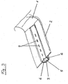
- FIG. 3 shows a partial sectional view of the bottom 2 of the washing container 1 of a dishwasher with a spraying device according to a second embodiment of the present invention.
- the spray channel 5 is formed closed, wherein the interior of the washing container 1 facing side of the spray channel 5 has openings 9 for the passage of the rinsing liquid.
- the spray channel 5 is further designed so that it is manually detachable from the bottom 2 of the washing container 1 and can be fixed again via a clamping connection. This makes it possible to remove the spray channel 5, if necessary, from the washing container 1, for example, to free it of deposits or to replace it with another spray channel 5.
- the spray channel 4 has a substantially rectangular, nearly square cross-section.
- the spray channel 5 has a trapezoidal cross section, with the distance between the side walls 6 of the spray channel 5 tapering from the side of the spray channel 5 facing the interior of the washing container 1 to the side of the spray channel 5 facing away from the interior of the washing container 1.
- such a spray channel can also be provided with a round or at least partially round, preferably circular cross-section. This, although more complicated to manufacture, would improve the hydronic parameters.
- FIG. 4 shows a partial sectional view of the bottom 2 of the washing compartment 1 of a dishwasher with a spraying device according to a third embodiment of the present invention.
- the direction of the interior of the washing container 1 side of the spray channel 4 is formed by the bottom 2 of the washing container 1, wherein the bottom 2 in the region of the spray channel 4 has openings 9 for the passage of the washing liquid.
- the remaining walls of the spray channel 4 and thus the spray channel 4 may be formed integrally with the bottom 2 of the washing container 1, wherein the openings 9 for the passage of the Rinsing fluid either introduced later or already provided during the preparation of the washing compartment 1.
- FIG. 5 shows a partial sectional view of the bottom 2 of the washing container 1 of a dishwasher with a spraying device according to a fourth embodiment of the present invention.
- the design of the spray channels 4 substantially corresponds to that in the FIGS. 1 and 2 illustrated embodiment.
- the washing container 1 is formed like a trough, wherein in the bottom 2 of the washing container 1, a number of preferably parallel aligned recesses is provided, which are provided with covers 7.
- the number of spray channels 4 should be adapted to the volume of the washing container 1 or to the surface of the dishwasher base 2.
- the bottom 2 of the washing container 1 is shaped in such a way that the spray channels 4 lie on different levels and thus a plurality of spray levels are formed.
- the provision of several spray channels 4, 5 favors a uniform spray distribution of the rinsing liquid in the rinsing tank 1, which is further improved by the arrangement of the spray channels 4 at different heights.
Description
Die Erfindung betrifft einen Geschirrspüler mit einem oder mehreren Spülbehältern und einer Vorrichtung zum Besprühen von im Spülbehälter angeordnetem Spülgut.The invention relates to a dishwasher with one or more washing containers and a device for spraying arranged in the washing container items.
Es sind Geschirrspüler mit Sprüheinrichtungen bekannt, die mit rotierenden Sprüharmen arbeiten. Da in den herkömmlichen Geschirrspülern der Spülbehälter üblicherweise einen rechteckigen Grundriss aufweist, während die rotierenden Sprüharme einen kreisförmigen Wirkungsbereich haben, können die jeweiligen Eckenbereiche durch die rotierenden Sprüharme nur unzulänglich mit Spülflüssigkeit besprüht werden. Darüber hinaus haben rotierende Sprüharme den Nachteil, dass es sich um bewegte Teile handelt, die sowohl dem bewegungsbedingten Verschleiß als auch einer erhöhten Störanfälligkeit unterliegen, wenn beispielsweise in den Bewegungsbereich des Sprüharms geratenes Spülgut die Rotation des Sprüharms behindert.There are dishwasher with sprayers are known to work with rotating spray arms. In the conventional dishwashers, since the washing container usually has a rectangular outline, while the rotating spray arms have a circular area of action, the respective corner areas can only be insufficiently sprayed with flushing liquid by the rotating spray arms. In addition, rotating spray arms have the disadvantage that they are moving parts, which are subject to both the movement-related wear and an increased susceptibility to interference when, for example, advised in the range of movement of the spray arm wash prevents the rotation of the spray arm.
Ferner sind im Stand der Technik Geschirrspülmaschinen mit Sprüheinrichtungen bekannt, bei denen über feststehende Sprühdüsen oder Sprühbrausen das im Spülbehälter befindliche Spülgut mit Spülflüssigkeit beaufschlagt wird. Solche Sprüheinrichtungen haben den Nachteil, dass sie in den Innenraum des Spülbehälters hineinragen und der austretende Sprühstrahl eine vorbestimmte Richtung hat, so daß eine gleichmäßige Reinigungswirkung des Spülguts nicht gewährleistet werden kann.Furthermore, in the prior art, dishwashers with spray devices are known in which rinsing liquid is applied to the items to be washed in the washing container via fixed spray nozzles or spray nozzles. Such spraying devices have the disadvantage that they protrude into the interior of the washing and the exiting spray has a predetermined direction, so that a uniform cleaning effect of the dishes can not be guaranteed.
Aus der
Aus der
Aus der
Aus der
Aufgabe der vorliegenden Erfindung ist es, eine Geschirrspülmaschine mit einer platzsparenden Vorrichtung zum Besprühen von Spülgut bereitzustellen, bei der die Spülflüssigkeit möglichst gleichmäßig im Spülbehälter eingesprüht wird, um das Spülgut effizient mit Spülflüssigkeit zu beaufschlagen, und der durch bewegte Teile bedingte Verschleiß sowie die Störanfälligkeit beseitigt wird.Object of the present invention is to provide a dishwasher with a space-saving device for spraying ware, in which the rinsing liquid is sprayed as evenly as possible in the washing to flush the wash ware efficiently, and eliminates the conditional by moving parts wear and susceptibility becomes.
Diese Aufgabe wird durch die erfindungsgemäße Vorrichtung mit den Merkmalen gemäß Anspruch 1 gelöst. Vorteilhafte Weiterbildungen der vorliegenden Erfindung sind in den Unteransprüchen 2 bis 11 gekennzeichnet.This object is achieved by the device according to the invention with the features of claim 1. Advantageous developments of the present invention are characterized in the
Der erfindungsgemäße Geschirrspüler umfasst mindestens einen Spülbehälter und eine Sprüheinrichtung zum Einsprühen von Spülflüssigkeit in den Innenraum des Spülbehälters, wobei die Sprüheinrichtung mindestens einen Spülflüssigkeit führenden Sprühkanal aufweist, der im Boden-, Decken- und/oder Wandbereich des Spülbehälters integriert ist und auf einer zum Innenraum des Spülbehälters gerichteten Seite Öffnungen für den Durchtritt der Spülflüssigkeit aufweist.The dishwasher according to the invention comprises at least one rinsing container and a spraying device for spraying rinsing liquid into the interior of the rinsing container, wherein the spraying device has at least one rinsing liquid-carrying spray channel, which is integrated in the floor, ceiling and / or wall region of the rinsing container and on the interior The flushing container side has openings for the passage of the rinsing liquid.
Ein Vorteil der Geschirrspülmaschine mit einer Sprüheinrichtung gemäß der vorliegenden Erfindung besteht zum einen darin, dass durch den im Boden-, Decken- oder Wandbereich des Spülbehälters integrierten Sprühkanal die gleichmäßige Sprühverteilung der Spülflüssigkeit im Spülbehälter verbessert wird. Zum anderen sind bei dem erfindungsgemäßen Geschirrspüler zur Leitung und Verteilung der Spülflüssigkeit keine bewegten Komponenten, wie z.B. Sprüharme, erforderlich und dadurch auch ein bewegungsbedingter Verschleiß bzw. die Störanfälligkeit von bewegten Teilen beseitigt. Dies hat zur Folge, dass beispielsweise herabfallende Geschirrteile die Sprühverteilung der Spülflüssigkeit nicht mehr stören, da keine mechanisch bewegten Teile mehr vorhanden sind, die in ihrem Bewegungsbereich behindert werden könnten.One advantage of the dishwasher with a spraying device according to the present invention is, on the one hand, that the uniform spray distribution of the rinsing liquid in the rinsing container is improved by the spray channel integrated in the base, ceiling or wall region of the rinsing container. On the other hand, in the dishwasher according to the invention for the administration and distribution of the rinsing liquid no moving components, such as e.g. Spray arms, required and thereby also a movement-related wear or the susceptibility of moving parts eliminated. This has the consequence that, for example, falling crockery parts no longer disturb the spray distribution of the rinsing liquid, since no more mechanically moving parts are present, which could be hindered in their range of motion.
Durch den Wegfall der Notwendigkeit von rotierenden Sprüharmen ergibt sich ferner der Vorteil, dass der zur Anordnung von Spülgut nutzbare Raum im Spülbehälter vergrößert wird. Die Geschirrteile können äußerst nahe am Boden-, Decken- oder Wandbereich des Spülbehälters angeordnet werden, da kein Bewegungsfreiraum für einen rotierenden Sprüharm mehr berücksichtigt werden muss. Darüber hinaus ist auch die Freiheit bei der Gestaltung der im Spülbehälter befindlichen Geschirrkörbe größer, da keine rotierenden Sprüharme oder aus den Boden-, Decken- oder Wandbereichen des Spülbehälters hervorstehende Komponenten zur Verteilung der Spülflüssigkeit mehr zu berücksichtigen sind.By eliminating the need for rotating spray arms, there is also the advantage that the usable space for the arrangement of items to be washed in the washing is increased. The crockery parts can be placed extremely close to the bottom, ceiling or wall area of the washing container, since no more freedom of movement for a rotating spray arm has to be taken into account. In addition, the freedom in the design of the dish racks located in the rinsing container is greater because no rotating spray arms or from the bottom, ceiling or wall portions of the rinse tank protruding components for distributing the rinsing liquid are more to be considered.
Noch ein weiterer Vorteil der Sprüheinrichtung der erfindungsgemäßen Geschirrspülmaschine besteht darin, dass Länge und Breite des Spülbehälters nicht mehr zwingend in einem Verhältnis von mindestens nahezu 1:1 ausgebildet sein müssen - wie das beispielsweise bei einer Sprüheinrichtung mit rotierenden Sprüharmen erforderlich ist -, sondern in nahezu beliebiger Form gestaltet werden kann, da die im Boden-, Decken- und/oder Wandbereich des Spülbehälters integrierten Sprühkanäle jeder Form des Spülbehälters entsprechend angepasst werden können.Yet another advantage of the spraying device of the dishwasher according to the invention is that the length and width of the washing container need not necessarily be formed in a ratio of at least almost 1: 1 - as required for example in a spraying device with rotating spray arms - but in almost can be designed in any shape, since the integrated in the bottom, ceiling and / or wall area of the washing container spray channels each shape of the Rinse container can be adjusted accordingly.
Um die Sprühverteilung der Spülflüssigkeit innerhalb des Spülbehälters möglichst optimal zu gestalten, werden die Form und/oder die Anzahl der Öffnungen für den Durchtritt der Spülflüssigkeit vorzugsweise so bestimmt, dass die gewünschte Spülung im Innenraum des Spülbehälters erzielt wird. Dabei kann eine möglichst gleichmäßige Sprühverteilung oder auch eine ungleichmäßige Sprühverteilung angestrebt werden, bei der bestimmte Bereiche im Spülbehälter stärker gespült werden als andere.In order to make the spray distribution of the rinsing liquid within the rinsing container as optimal as possible, the shape and / or the number of openings for the passage of the rinsing liquid are preferably determined such that the desired rinsing is achieved in the interior of the rinsing container. In this case, the most uniform possible spray distribution or even a non-uniform spray distribution can be sought, in which certain areas are rinsed in the washing more than others.
Bei einer bevorzugten Ausführungsform der Geschirrspülmaschine mit einer Sprüheinrichtung gemäß der vorliegenden Erfindung ist der mindestens eine Sprühkanal rohrartig ausgebildet und weist vorzugsweise zwei offene Enden auf, über die Spülflüssigkeit druckbeaufschlagt zugeführt werden kann. Auf diese Weise können beiden Enden des rohrartigen Sprühkanals unabhängig voneinander Spülflüssigkeit unter Druck zugeführt werden. Dabei wird die Zufuhr der Spülflüssigkeit zum Sprühkanal durch eine Pumpeinrichtung, wie z.B. die Umwälzpumpe der Geschirrspülmaschine, bewerkstelligt. Erfindungsgemäß ist dabei der Druck, mit dem die Spülflüssigkeit dem Sprühkanal über sein eines Ende oder über seine beiden Enden zugeführt wird, variierbar. Das heißt, dass entweder der Druck für die Zufuhr von Spülflüssigkeit nur über ein Ende des Sprühkanals oder der Druck für die Zufuhr von Spülflüssigkeit über beide Enden des Sprühkanals variierbar ist.In a preferred embodiment of the dishwasher with a spraying device according to the present invention, the at least one spray channel is tube-like and preferably has two open ends, can be supplied pressurized via the rinsing liquid. In this way, irrigation fluid can be fed under pressure to both ends of the tubular spray channel independently of one another. In this case, the supply of the rinsing liquid to the spray channel by a pumping device, such. the circulating pump of the dishwasher, accomplished. In accordance with the invention, the pressure with which the rinsing liquid is supplied to the spray channel via its one end or via its two ends can be varied. That is, either the pressure for the supply of rinsing liquid can be varied only via one end of the spray channel or the pressure for the supply of rinsing liquid over both ends of the spray channel.
Die Zufuhr von Spülflüssigkeit zum Sprühkanal mit zeitlich variierbarem Druck ermöglicht das Erzeugen von Sprühmustern, das beispielsweise auf bestimmtes Spülgut angepasst werden kann. Die Sprühmuster entstehen durch die unterschiedliche Druckverteilung der Spülflüssigkeit im Sprühkanal, die sich durch die zeitliche Variation des Drucks ergibt, mit dem die Zufuhr von Spülflüssigkeit über die beiden Enden des Sprühkanals vorgenommen wird, wobei der an dem einen Ende des Sprühkanals erzeugte Flüssigkeitsdruck zu dem an dem anderen Ende des Sprühkanals erzeugten Flüssigkeitsdruck unterschiedlich ist. Dadurch treten aus den Öffnungen des Sprühkanals unterschiedlich starke Strahlen von Spülflüssigkeit mit unterschiedlichem Druck in den Innenraum des Spülbehälters aus. Durch die unterschiedliche Druckbeanschlagung an den Enden des Sprühkanales kann das Druckmaximum im Sprühkananl, d. h. der Ort entlang des Kanales, in welchem der austretende Strahl seine max. Impulskraft besitzt variiert werden.The supply of rinsing liquid to the spray channel with temporally variable pressure allows the generation of spray patterns, which can be adapted for example to specific items to be washed. The spray patterns are caused by the different pressure distribution of the rinsing liquid in the spray channel, which results from the temporal variation of the pressure with which the supply of rinsing liquid is made via the two ends of the spray channel, wherein the liquid pressure generated at one end of the spray channel to the the fluid pressure generated at the other end of the spray channel is different. As a result, differently strong jets of rinsing liquid with different pressure emerge from the openings of the spray channel into the interior of the rinsing container. Due to the different Druckbeanschlagung at the ends of Sprühkanales the maximum pressure in Sprühkananl, ie the place along the channel, in which the exiting beam its max. Momentum possesses to be varied.
Die Variation des Drucks, mit dem die Spülflüssigkeit dem Sprühkanal zugeführt wird, kann durch eine Druckverteilung mit elektronischen, hydraulischen oder mechanischen Mitteln gesteuert werden. Die Verwendung einer elektronisch gesteuerten Druckverteilung hat den Vorteil, dass wiederum keine rotierenden oder beweglichen Komponenten erforderlich sind, da sowohl die Sprühintensität als auch das Sprühmuster über einen kontrollierten Druckablauf und Drucksteuerung vorgenommen wird. Dabei kann entsprechend einer Spülprogrammwahl eine Vielzahl von unterschiedlichen Sprühmustern erzeugt werden. Bei der Auswahl der Sprühmuster ist es möglich, die unterschiedlichen Verschmutzungszustände und die Art des Spülguts zu berücksichtigen.The variation of the pressure with which the rinsing liquid is supplied to the spray channel can be controlled by a pressure distribution with electronic, hydraulic or mechanical means. The use of an electronically controlled pressure distribution has the advantage that in turn no rotating or moving components are required, since both the spray intensity and the spray pattern is carried out via a controlled pressure and pressure control. In this case, a plurality of different spray patterns can be generated in accordance with a wash program selection. When selecting the spray patterns, it is possible to take into account the different soiling conditions and the type of items to be washed.
Bei einer weiteren bevorzugten Ausführungsform der vorliegenden Erfindung liegt die zum Innenraum des Spülbehälters gerichtete Seite des Sprühkanals im wesentlichen in einer Ebene mit der zum Innenraum des Spülbehälters gerichteten Boden-, Decken- oder Wandfläche des Spülbehälters, in welcher der Sprühkanal integriert ist. Daraus ergeben sich am Boden-, Decken- oder Wandbereich des Spülbehälters ebene Flächen, die einerseits ein ansprechendes optisches Erscheinungsbild bieten und andererseits die Anordnung von Spülgut in unmittelbarer Nähe zum Boden-, Decken- oder Wandbereich des Spülbehälters ermöglichen.In a further preferred embodiment of the present invention, the directed to the interior of the washing container side of the spray is substantially in a plane with the directed to the interior of the Spülbehälters bottom, ceiling or wall surface of the washing, in which the spray channel is integrated. This results in the floor, ceiling or wall area of the Spülbehälters flat surfaces, on the one hand offer a pleasing visual appearance and on the other hand allow the arrangement of items in close proximity to the floor, ceiling or wall area of the washing.
Der Sprühkanal hat bevorzugterweise einen runden, vorzugsweise kreisrunden Querschnitt. Damit können die hydraulischen Verluste klein gehalten werden.The spray channel preferably has a round, preferably circular cross-section. Thus, the hydraulic losses can be kept small.
Zur Ergänzung konstrukiver Vorteile kann der Sprühkanal aber auch einen rechteckigen, vorzugsweise im wesentlichen quadratischen Querschnitt aufweisen, wobei eine Seite des Sprühkanals zum Innenraum des Spülbehälters gerichtet ist. Erfindungsgemäß ist der Sprühkanal aus dem Boden-, Decken- oder Wandbereich des Spülbehälters manuell lösbar ausgebildet und vorzugsweise über eine Klemmverbindung im Boden-, Decken- und/oder Wandbereich des Spülbehälters fixierbar. Dadurch kann der Sprühkanal bei Bedarf aus dem Spülbehälter entfernt werden, um ihn beispielsweise von Ablagerungen zu befreien. Er kann aber auch durch einen anderen Sprühkanal mit abweichenden Öffnungen für den Austritt von Spülflüssigkeit ersetzt werden, um ein anderes Sprühmuster zu erhalten.To supplement constructive advantages of the spray channel but also have a rectangular, preferably substantially square cross-section, wherein one side of the spray channel is directed to the interior of the washing compartment. According to the invention, the spray channel is designed to be manually detachable from the floor, ceiling or wall region of the washing container and can preferably be fixed via a clamping connection in the floor, ceiling and / or wall region of the washing container. As a result, the spray channel can be removed if necessary from the washing, for example, to rid it of deposits. But it can also be replaced by another spray channel with different openings for the escape of rinsing liquid to a to obtain different spray pattern.
Alternativ oder zusätzlich kann eine zum Innenraum des Spülbehälters gerichtete Wand des Sprühkanals manuell lösbar ausgebildet sein, wobei die betreffende Seite vorzugsweise über eine Klemmverbindung im Boden-, Decken- und/oder Wandbereich des Spülbehälters auf dem Sprühkanal fixierbar ist. Die abnehmbare Seite des Sprühkanals ermöglicht es, diese wie einen Deckel vom Sprühkanal zu entfernen, um einen Zugang zum Inneren des Sprühkanals zu erhalten. Dabei ist es von besonderem Nutzen, wenn die abnehmbare Seite des Sprühkanals auch die Seite ist, welche die Öffnungen für den Durchtritt der Spülflüssigkeit aus dem Sprühkanal in den Innenraum des Spülbehälters aufweis. Dadurch kann bei Bedarf nur der Deckel des Sprühkanals entfernt werden, um beispielsweise die Öffnungen von Ablagerungen zu befreien, das Innere des Sprühkanals zu inspizieren oder durch einen anderen Deckel zu ersetzen.Alternatively or additionally, a wall of the spray channel directed toward the interior of the washing container may be designed to be detachable by hand, the side being preferably fixable on the spray channel via a clamping connection in the base, ceiling and / or wall region of the washing container. The removable side of the spray channel allows it to be removed like a lid from the spray channel to gain access to the interior of the spray channel. It is particularly useful if the removable side of the spray channel is also the side which has the openings for the passage of the rinsing liquid from the spray channel into the interior of the washing compartment. Thereby, if necessary, only the cover of the spray channel can be removed, for example, to clear the openings of deposits, to inspect the interior of the spray channel or to replace it with another cover.
Die zum Innenraum des Spülbehälters gerichtete Seite des Sprühkanals kann jedoch auch durch die Decke, die Wand und/oder den Boden des Spülbehälters gebildet sein, wobei die Decke, die Wand und/oder der Boden im Bereich des Sprühkanals die Öffnungen für den Durchtritt der Spülflüssigkeit aufweisen. Bei dieser Ausführungsform ist zumindest die zum Innenraum des Spülbehälters gerichtete Seite des Sprühkanals und die Decke, die Wand und/oder der Boden des Spülbehälters einstückig ausgebildet. Da die Spülbehälter üblicherweise aus Kunststoff hergestellt sind, können die Öffnungen für den Durchtritt der Spülflüssigkeit entweder nachträglich eingebracht oder bereits während der Herstellung des Spülbehälters vorgesehen werden. Darüber hinaus kann auch der gesamte Sprühkanal mit der Decke, der Wand und/oder dem Boden des Spülbehälters einstückig ausgebildet und bereits bei der Herstellung des Spülbehälters vorgesehen werden.However, the side of the spray channel directed towards the interior of the washing container may also be formed by the ceiling, the wall and / or the bottom of the washing container, wherein the ceiling, the wall and / or the bottom in the region of the spray channel, the openings for the passage of the washing liquid exhibit. In this embodiment, at least the directed to the interior of the washing container side of the spray channel and the ceiling, the wall and / or the bottom of the washing container is integrally formed. Since the rinsing containers are usually made of plastic, the openings for the passage of the rinsing liquid can either be introduced subsequently or already provided during the production of the rinsing container. In addition, the entire spray channel with the ceiling, the wall and / or the bottom of the washing can be formed in one piece and already provided during the preparation of the washing.
Bei einer besonders vorteilhaften Ausführungsform der erfindungsgemäßen Geschirrspülmaschine ist der Spülbehälter wannenartig ausgebildet, und zumindest im Boden des Spülbehälters ist eine Anzahl von vorzugsweise parallel zueinander ausgerichteten Sprühkanälen integriert. Grundsätzlich richtet sich die Anzahl der Sprühkanäle nach dem Volumen des Spülbehälters bzw. nach der Fläche des Geschirrspülerbodens. Die Einrichtung mehrerer Sprühkanäle begünstigt eine gleichmäßige Sprühverteilung der Spülflüssigkeit im Spülbehälter und verhindert die "Abschaltung" von Sprühstrahlen durch das Spülgut. Dabei kann der Boden des Spülbehälters derart geformt sein, dass die Sprühkanäle auf unterschiedlichen Ebenen liegen und damit mehrere Sprühebenen gebildet werden.In a particularly advantageous embodiment of the dishwasher according to the invention, the washing container is formed like a tub, and at least in the bottom of the washing container a number of preferably parallel aligned spray channels is integrated. In principle, the number of spray channels depends on the volume of the washing container or on the surface of the dishwasher base. The establishment of several spray channels promotes a uniform spray distribution of the rinsing liquid in the washing and prevents the "Shutdown" of spray through the dishes. In this case, the bottom of the washing container can be shaped such that the spray channels are at different levels and thus a plurality of spray levels are formed.
Im Folgenden wird die vorliegende Erfindung anhand von bevorzugten Ausführungsbeispielen unter Bezugnahme auf die beigefügten Zeichnungen näher erläutert. Es zeigen
- Figur 1
- eine teilweise Schnittdarstellung vom Boden des Spülbehälters einer Geschirrspülmaschine mit einer Sprühvorrichtung gemäß einer ersten Ausführungsform der vorliegenden Erfindung,
Figur 2- eine zweite teilweise Schnittdarstellung vom Boden des Spülbehälters einer Geschirrspülmaschine mit einer Sprühvorrichtung gemäß der in
Figur 1 dargestellten Ausführungsform, Figur 3- eine teilweise Schnittdarstellung vom Boden des Spülbehälters einer Geschirrspülmaschine mit einer Sprühvorrichtung gemäß einer zweiten Ausführungsform der vorliegenden Erfindung,
Figur 4- eine teilweise Schnittdarstellung vom Boden des Spülbehälters einer Geschirrspülmaschine mit einer Sprühvorrichtung gemäß einer dritten Ausführungsform der vorliegenden Erfindung und
Figur 5- eine teilweise Schnittdarstellung vom Boden des Spülbehälters einer Geschirrspülmaschine mit einer Sprühvorrichtung gemäß einer vierten Ausführungsform der vorliegenden Erfindung.
- FIG. 1
- a partial sectional view from the bottom of the washing container of a dishwasher with a spraying device according to a first embodiment of the present invention,
- FIG. 2
- a second partial sectional view from the bottom of the washing container of a dishwasher with a spraying device according to the in
FIG. 1 illustrated embodiment, - FIG. 3
- a partial sectional view from the bottom of the washing container of a dishwasher with a spraying device according to a second embodiment of the present invention,
- FIG. 4
- a partial sectional view from the bottom of the washing container of a dishwasher with a spraying device according to a third embodiment of the present invention and
- FIG. 5
- a partial sectional view from the bottom of the washing container of a dishwasher with a spraying device according to a fourth embodiment of the present invention.
Bei dieser ersten Ausführungsform weist die Abdeckung 7 einen symmetrischen und im wesentlichen U-förmigen Querschnitt auf, wobei die beiden freien Enden des U-förmigen Querschnitts durch Schenkel 8 gebildet werden. Die Abdeckung 7 ist aus einem elastischen Material gefertigt, so dass die Schenkel 8 flexibel gegen eine Vorspannung zueinander gebogen werden können. Auf diese Weise bildet sich zwischen den Schenkeln 8 und der Seitenwand 6 des Sprühkanals 4 eine Klemmverbindung, wodurch die Abdeckung 7 im Boden 2 des Spülbehälters 1 auf dem Sprühkanal 4 fixiert ist. Die abnehmbare Abdeckung 7 des Sprühkanals 4 ermöglicht es, diese bei Bedarf wie einen Deckel vom Sprühkanal 4 zu entfernen, um beispielsweise das Innere des Sprühkanals 4 zu inspizieren und von Ablagerungen zu befreien oder eine andere Abdeckung 7 anzubringen.In this first embodiment, the
In
Anders als hier aus praktischen Erwägungen gewählt, kann ein solcher Sprühkanal aber auch mit einem runden oder wenigstens teilweise runden, vorzugsweise kreisrunden Querschnitt versehen sein. Dies würde, wenn auch komplizierter für die Herstellung, die hydralischen Parameter verbessern.Unlike chosen here for practical considerations, such a spray channel can also be provided with a round or at least partially round, preferably circular cross-section. This, although more complicated to manufacture, would improve the hydronic parameters.
- 11
- Spülbehälterrinse tank
- 22
- Boden des SpülbehältersBottom of the washing container
- 33
- Vertiefung im Boden des SpülbehältersDeepening in the bottom of the washing container
- 44
- Sprühkanal mit rechteckigem QuerschnittSpray channel with rectangular cross section
- 55
- Sprühkanal mit konischem QuerschnittSpray channel with conical cross section
- 66
- Seitenwand des SprühkanalsSide wall of the spray channel
- 77
- Abdeckung des SprühkanalsCover the spray channel
- 88th
- Schenkel der Abdeckung des SprühkanalsLegs of the cover of the spray channel
- 99
- Öffnungen für den Durchtritt von SpülflüssigkeitOpenings for the passage of rinsing liquid
- 1010
- Spülgutware
Claims (11)
- Dishwasher comprising at least one dishwasher cavity (1) and a spraying device for spraying washing liquid into the interior of the dishwasher cavity (1), the spraying device having at least one spray channel (4, 5) guiding therealong at least one washing liquid, the spray channel being integrated into the bottom, top and/or wall area of the dishwasher cavity (1) and having openings (9) in a side (7) of the spray channel (1) oriented in a direction towards the interior of the dishwasher cavity (1) for the passage therethrough of washing liquid, characterised in that the spray channel (4, 5) is formed to enable it to be manually released from the bottom area, top area or a wall area of the dishwasher cavity (1).
- Dishwasher according to claim 1, wherein the spray channel (4, 5) is embodied as tubular and preferably has two open ends via which washing liquid can be supplied under the action of pressure.
- Dishwasher according to one of the preceding claims, wherein the pressure with which the washing liquid is being supplied to the spray channel (4, 5) can be varied.
- Dishwasher according to claim 3, wherein the variation in pressure with which the washing liquid is supplied to the spray channel (4, 5) can be controlled by a pressure distribution using electronic, hydraulic and/or mechanical means.
- Dishwasher according to one of the preceding claims, wherein the side of the spray channel (4, 5) directed towards the interior of the dishwasher cavity (1) lies substantially in one plane with the surface of the bottom, top or wall areas of the dishwasher cavity (1) directed towards the interior of the dishwasher cavity (1) in which the spray channel (4, 5) is integrated.
- Dishwasher according to one of the preceding claims, characterised in that the spray channel (4, 5) has a round, preferably circular cross-section.
- Dishwasher according to one of the preceding claims, wherein the spray channel (4, 5) has a rectangular cross-section that is preferably essentially square.
- Dishwasher according to one of the preceding claims, wherein the spray channel (4, 5) can be fixed by a clamp connection in the bottom, top and/or wall area of the dishwasher cavity (1).
- Dishwasher according to one of the preceding claims, wherein a wall (7) of the spray channel (4, 5) directed towards the interior of the dishwasher cavity (1) can be embodied in such a way that it can be manually released and can preferably be fixed to the spray channel (4, 5) via a clamp connection (6) in the bottom, top and/or wall area of the dishwasher cavity.
- Dishwasher according to one of the preceding claims, wherein the side of the spray channel (4, 5) directed towards the interior of the dishwasher cavity (1) is formed by the top, wall and/or bottom area (2) of the dishwasher cavity (1), wherein the top, wall and/or bottom area (2) of the dishwasher cavity has openings (7) for the passage of the washing liquid in the area of the spray channel (4, 5).
- Dishwasher according to one of the preceding claims, wherein the dishwasher cavity (1) has a trough configuration and further comprises a number of spray channels (4, 5) aligned parallel to one another integrated at least into the bottom area (2) ofthe dishwasher cavity (1).
Applications Claiming Priority (2)
| Application Number | Priority Date | Filing Date | Title |
|---|---|---|---|
| DE10346676A DE10346676A1 (en) | 2003-10-08 | 2003-10-08 | Dishwasher with integrated spray channels |
| PCT/EP2004/011270 WO2005034712A1 (en) | 2003-10-08 | 2004-10-08 | Dishwasher with integrated spray channels |
Publications (2)
| Publication Number | Publication Date |
|---|---|
| EP1673000A1 EP1673000A1 (en) | 2006-06-28 |
| EP1673000B1 true EP1673000B1 (en) | 2013-06-05 |
Family
ID=34399353
Family Applications (1)
| Application Number | Title | Priority Date | Filing Date |
|---|---|---|---|
| EP04765895.0A Not-in-force EP1673000B1 (en) | 2003-10-08 | 2004-10-08 | Dishwasher with integrated spray channels |
Country Status (6)
| Country | Link |
|---|---|
| US (1) | US7887642B2 (en) |
| EP (1) | EP1673000B1 (en) |
| CN (1) | CN100591260C (en) |
| DE (1) | DE10346676A1 (en) |
| NZ (1) | NZ546281A (en) |
| WO (1) | WO2005034712A1 (en) |
Families Citing this family (9)
| Publication number | Priority date | Publication date | Assignee | Title |
|---|---|---|---|---|
| WO2005060813A1 (en) * | 2003-12-22 | 2005-07-07 | BSH Bosch und Siemens Hausgeräte GmbH | Dishwasher having fixed spraying nozzles |
| ATE413524T1 (en) | 2006-03-02 | 2008-11-15 | Fiat Ricerche | COMBUSTION ENGINE WITH MEANS FOR DETERMINING FRESH AIR MASS, AND ASSOCIATED METHOD FOR DETERMINING |
| US20120111376A1 (en) * | 2010-11-08 | 2012-05-10 | Worrasangasilpa Brian | Device for pre-rinsing objects in an appliance utilizing line pressure of a fluid supply |
| DE102012202246B4 (en) | 2012-02-15 | 2024-02-08 | BSH Hausgeräte GmbH | Dishwasher with a spray device |
| US9155447B2 (en) | 2012-11-13 | 2015-10-13 | Whirlpool Corporation | Dish rack with integral hydraulic circuit |
| US9713414B2 (en) | 2013-06-21 | 2017-07-25 | Whirlpool Corporation | Dishwasher having a conduit framework |
| US9895043B2 (en) | 2015-08-26 | 2018-02-20 | Whirlpool Corporation | Method of using high velocity water to remove puddling in a dishwasher |
| CN108464805A (en) * | 2018-04-17 | 2018-08-31 | 浙江欧琳生活健康科技有限公司 | A kind of boosting type pulse cleaning equipment |
| US11147430B2 (en) | 2019-03-27 | 2021-10-19 | Midea Group Co., Ltd. | Dishwasher including rack corner sprayers |
Citations (1)
| Publication number | Priority date | Publication date | Assignee | Title |
|---|---|---|---|---|
| DE1403670A1 (en) * | 1960-07-11 | 1968-10-24 | Siemens Elektorgeraete Gmbh | Dishwasher |
Family Cites Families (19)
| Publication number | Priority date | Publication date | Assignee | Title |
|---|---|---|---|---|
| US2630813A (en) | 1948-06-23 | 1953-03-10 | Charles A Murdoch | Spray manifold for washing machines |
| FR1265156A (en) * | 1958-04-17 | 1961-06-30 | Dish washing and drying machine and the like | |
| DE1103787B (en) * | 1959-05-16 | 1961-03-30 | Moreton Engineering Company Lt | Device for cleaning vessels provided with a handle |
| GB949954A (en) * | 1960-12-23 | 1964-02-19 | Apv Co Ltd | A new or improved method of or apparatus for producing a liquid spray |
| DE1847897U (en) * | 1961-11-21 | 1962-03-08 | Hans Engel | DISHWASHER OR WASHING MACHINE OD. DGL. |
| DE1926024U (en) * | 1964-06-24 | 1965-10-28 | Heinrich Puzelik Formenbau U S | MUZZLE. |
| GB1138291A (en) * | 1965-06-14 | 1968-12-27 | Edward Gelles | Dish washing device |
| FR2009078A1 (en) | 1968-05-22 | 1970-01-30 | Sandoz Sa | N-substd n-acyl pyrazolidine cpds intermediates for |
| US3777989A (en) * | 1972-04-14 | 1973-12-11 | G Pacella | Dishwasher with cycle timing system |
| US3884263A (en) * | 1973-09-14 | 1975-05-20 | Kenneth F A Wright | Dishwashing machine |
| CH654195A5 (en) * | 1983-06-30 | 1986-02-14 | Daniel Roulin | WASHING DEVICE FOR ICE CREAM SPOONS. |
| US5357993A (en) * | 1992-09-25 | 1994-10-25 | St Martin Marty | Produce washer |
| IT1294116B1 (en) | 1997-02-11 | 1999-03-22 | Electrolux Zanussi Elettrodome | DOMESTIC DISHWASHER |
| DE19720759C2 (en) * | 1997-05-07 | 1999-03-04 | Berliner Stadtreinigungsbetrie | Floor cleaning / disinfection system |
| CH692436A5 (en) * | 1997-12-22 | 2002-06-14 | Kontakt Systeme Ag | Telecommunications plug-in distributor has projections of plug screening acting as supports for printed circuit board fitted with sockets |
| FR2784886B1 (en) * | 1998-10-26 | 2001-03-02 | Sabine Renne Josephine Cabello | MINI CUTLERY WASHING MACHINE |
| DE20007044U1 (en) * | 2000-04-17 | 2000-07-06 | Schardt Friedrich | Cleaning device |
| DE10162501A1 (en) * | 2001-12-19 | 2003-07-10 | Bsh Bosch Siemens Hausgeraete | Device and method for washing dishes in a dishwasher |
| US6869029B2 (en) * | 2002-04-02 | 2005-03-22 | Distinctive Appliances, Inc. | Water spray system for a dishwasher |
-
2003
- 2003-10-08 DE DE10346676A patent/DE10346676A1/en not_active Withdrawn
-
2004
- 2004-10-08 CN CN200480029654A patent/CN100591260C/en not_active Expired - Fee Related
- 2004-10-08 EP EP04765895.0A patent/EP1673000B1/en not_active Not-in-force
- 2004-10-08 US US10/575,176 patent/US7887642B2/en not_active Expired - Fee Related
- 2004-10-08 NZ NZ546281A patent/NZ546281A/en not_active IP Right Cessation
- 2004-10-08 WO PCT/EP2004/011270 patent/WO2005034712A1/en active Application Filing
Patent Citations (1)
| Publication number | Priority date | Publication date | Assignee | Title |
|---|---|---|---|---|
| DE1403670A1 (en) * | 1960-07-11 | 1968-10-24 | Siemens Elektorgeraete Gmbh | Dishwasher |
Also Published As
| Publication number | Publication date |
|---|---|
| US20070074746A1 (en) | 2007-04-05 |
| CN1867289A (en) | 2006-11-22 |
| US7887642B2 (en) | 2011-02-15 |
| CN100591260C (en) | 2010-02-24 |
| WO2005034712A1 (en) | 2005-04-21 |
| DE10346676A1 (en) | 2005-05-04 |
| NZ546281A (en) | 2009-07-31 |
| EP1673000A1 (en) | 2006-06-28 |
Similar Documents
| Publication | Publication Date | Title |
|---|---|---|
| EP2192852B1 (en) | Dishwasher | |
| DE19812231A1 (en) | dishwasher | |
| DE102006018539A1 (en) | Dishwasher, in particular domestic dishwasher | |
| DE102009033895A1 (en) | Automatic dishwasher with several spray zones | |
| DE10134917B4 (en) | Dishwasher with variable liquid distribution | |
| DE1935139U (en) | WASHING DEVICE, IN PARTICULAR FOR WASHING CUTLERY. | |
| DE102012109386A1 (en) | Dishwasher with auxiliary detergent dispenser | |
| EP1700943A1 (en) | Washing machine with injection nozzle | |
| EP1673000B1 (en) | Dishwasher with integrated spray channels | |
| EP2635172A1 (en) | Dishwasher comprising at least one rotatable spray arm | |
| DE102016208112B4 (en) | Dish rack for holding items to be washed and dishwasher, in particular household dishwasher | |
| DE19544985A1 (en) | dishwasher | |
| DE60130882T2 (en) | Dishwasher with an additional cutlery basket | |
| EP1701645B1 (en) | Dishwasher having fixed spraying nozzles | |
| EP1681976B1 (en) | Device for controlling spray channels in dishwasher machines | |
| DE19736919B4 (en) | Dishwasher with at least one washing level | |
| DE19926962A1 (en) | Dishwasher with height-adjustable basket | |
| DE102004063286A1 (en) | Dishwasher with a dissolution chamber | |
| DE8516941U1 (en) | Dishwasher with a spout with detergent | |
| DE2622785C3 (en) | Dishwasher with a device for controlling the pressure of the washing water in the spray arms | |
| DE102012107260B4 (en) | dishwasher | |
| DE3114951A1 (en) | Apparatus with a processing chamber for the processing, in particular the smoking and/or boiling, of meat and/or sausage products | |
| WO2021018610A1 (en) | Domestic dishwasher | |
| WO2002039871A1 (en) | Adapter for a dish basket of a dishwasher | |
| EP0752492A1 (en) | Washing products dispenser |
Legal Events
| Date | Code | Title | Description |
|---|---|---|---|
| PUAI | Public reference made under article 153(3) epc to a published international application that has entered the european phase |
Free format text: ORIGINAL CODE: 0009012 |
|
| 17P | Request for examination filed |
Effective date: 20060508 |
|
| AK | Designated contracting states |
Kind code of ref document: A1 Designated state(s): AT BE BG CH CY CZ DE DK EE ES FI FR GB GR HU IE IT LI LU MC NL PL PT RO SE SI SK TR |
|
| DAX | Request for extension of the european patent (deleted) | ||
| 17Q | First examination report despatched |
Effective date: 20110810 |
|
| GRAP | Despatch of communication of intention to grant a patent |
Free format text: ORIGINAL CODE: EPIDOSNIGR1 |
|
| GRAS | Grant fee paid |
Free format text: ORIGINAL CODE: EPIDOSNIGR3 |
|
| GRAA | (expected) grant |
Free format text: ORIGINAL CODE: 0009210 |
|
| AK | Designated contracting states |
Kind code of ref document: B1 Designated state(s): AT BE BG CH CY CZ DE DK EE ES FI FR GB GR HU IE IT LI LU MC NL PL PT RO SE SI SK TR |
|
| REG | Reference to a national code |
Ref country code: GB Ref legal event code: FG4D Free format text: NOT ENGLISH |
|
| REG | Reference to a national code |
Ref country code: CH Ref legal event code: EP |
|
| REG | Reference to a national code |
Ref country code: AT Ref legal event code: REF Ref document number: 615156 Country of ref document: AT Kind code of ref document: T Effective date: 20130615 |
|
| REG | Reference to a national code |
Ref country code: IE Ref legal event code: FG4D Free format text: LANGUAGE OF EP DOCUMENT: GERMAN |
|
| REG | Reference to a national code |
Ref country code: DE Ref legal event code: R096 Ref document number: 502004014214 Country of ref document: DE Effective date: 20130801 |
|
| PG25 | Lapsed in a contracting state [announced via postgrant information from national office to epo] |
Ref country code: SE Free format text: LAPSE BECAUSE OF FAILURE TO SUBMIT A TRANSLATION OF THE DESCRIPTION OR TO PAY THE FEE WITHIN THE PRESCRIBED TIME-LIMIT Effective date: 20130605 Ref country code: ES Free format text: LAPSE BECAUSE OF FAILURE TO SUBMIT A TRANSLATION OF THE DESCRIPTION OR TO PAY THE FEE WITHIN THE PRESCRIBED TIME-LIMIT Effective date: 20130916 Ref country code: GR Free format text: LAPSE BECAUSE OF FAILURE TO SUBMIT A TRANSLATION OF THE DESCRIPTION OR TO PAY THE FEE WITHIN THE PRESCRIBED TIME-LIMIT Effective date: 20130906 Ref country code: FI Free format text: LAPSE BECAUSE OF FAILURE TO SUBMIT A TRANSLATION OF THE DESCRIPTION OR TO PAY THE FEE WITHIN THE PRESCRIBED TIME-LIMIT Effective date: 20130605 Ref country code: SI Free format text: LAPSE BECAUSE OF FAILURE TO SUBMIT A TRANSLATION OF THE DESCRIPTION OR TO PAY THE FEE WITHIN THE PRESCRIBED TIME-LIMIT Effective date: 20130605 |
|
| REG | Reference to a national code |
Ref country code: NL Ref legal event code: VDEP Effective date: 20130605 |
|
| PG25 | Lapsed in a contracting state [announced via postgrant information from national office to epo] |
Ref country code: BG Free format text: LAPSE BECAUSE OF FAILURE TO SUBMIT A TRANSLATION OF THE DESCRIPTION OR TO PAY THE FEE WITHIN THE PRESCRIBED TIME-LIMIT Effective date: 20130905 Ref country code: PL Free format text: LAPSE BECAUSE OF FAILURE TO SUBMIT A TRANSLATION OF THE DESCRIPTION OR TO PAY THE FEE WITHIN THE PRESCRIBED TIME-LIMIT Effective date: 20130605 |
|
| PG25 | Lapsed in a contracting state [announced via postgrant information from national office to epo] |
Ref country code: PT Free format text: LAPSE BECAUSE OF FAILURE TO SUBMIT A TRANSLATION OF THE DESCRIPTION OR TO PAY THE FEE WITHIN THE PRESCRIBED TIME-LIMIT Effective date: 20131007 Ref country code: SK Free format text: LAPSE BECAUSE OF FAILURE TO SUBMIT A TRANSLATION OF THE DESCRIPTION OR TO PAY THE FEE WITHIN THE PRESCRIBED TIME-LIMIT Effective date: 20130605 Ref country code: CZ Free format text: LAPSE BECAUSE OF FAILURE TO SUBMIT A TRANSLATION OF THE DESCRIPTION OR TO PAY THE FEE WITHIN THE PRESCRIBED TIME-LIMIT Effective date: 20130605 Ref country code: EE Free format text: LAPSE BECAUSE OF FAILURE TO SUBMIT A TRANSLATION OF THE DESCRIPTION OR TO PAY THE FEE WITHIN THE PRESCRIBED TIME-LIMIT Effective date: 20130605 |
|
| PG25 | Lapsed in a contracting state [announced via postgrant information from national office to epo] |
Ref country code: NL Free format text: LAPSE BECAUSE OF FAILURE TO SUBMIT A TRANSLATION OF THE DESCRIPTION OR TO PAY THE FEE WITHIN THE PRESCRIBED TIME-LIMIT Effective date: 20130605 Ref country code: RO Free format text: LAPSE BECAUSE OF FAILURE TO SUBMIT A TRANSLATION OF THE DESCRIPTION OR TO PAY THE FEE WITHIN THE PRESCRIBED TIME-LIMIT Effective date: 20130605 |
|
| PLBE | No opposition filed within time limit |
Free format text: ORIGINAL CODE: 0009261 |
|
| STAA | Information on the status of an ep patent application or granted ep patent |
Free format text: STATUS: NO OPPOSITION FILED WITHIN TIME LIMIT |
|
| BERE | Be: lapsed |
Owner name: BSH BOSCH UND SIEMENS HAUSGERATE G.M.B.H. Effective date: 20131031 |
|
| PG25 | Lapsed in a contracting state [announced via postgrant information from national office to epo] |
Ref country code: DK Free format text: LAPSE BECAUSE OF FAILURE TO SUBMIT A TRANSLATION OF THE DESCRIPTION OR TO PAY THE FEE WITHIN THE PRESCRIBED TIME-LIMIT Effective date: 20130605 |
|
| 26N | No opposition filed |
Effective date: 20140306 |
|
| PG25 | Lapsed in a contracting state [announced via postgrant information from national office to epo] |
Ref country code: MC Free format text: LAPSE BECAUSE OF FAILURE TO SUBMIT A TRANSLATION OF THE DESCRIPTION OR TO PAY THE FEE WITHIN THE PRESCRIBED TIME-LIMIT Effective date: 20130605 Ref country code: IT Free format text: LAPSE BECAUSE OF FAILURE TO SUBMIT A TRANSLATION OF THE DESCRIPTION OR TO PAY THE FEE WITHIN THE PRESCRIBED TIME-LIMIT Effective date: 20130605 |
|
| REG | Reference to a national code |
Ref country code: CH Ref legal event code: PL |
|
| REG | Reference to a national code |
Ref country code: DE Ref legal event code: R097 Ref document number: 502004014214 Country of ref document: DE Effective date: 20140306 |
|
| GBPC | Gb: european patent ceased through non-payment of renewal fee |
Effective date: 20131008 |
|
| REG | Reference to a national code |
Ref country code: IE Ref legal event code: MM4A |
|
| PG25 | Lapsed in a contracting state [announced via postgrant information from national office to epo] |
Ref country code: LI Free format text: LAPSE BECAUSE OF NON-PAYMENT OF DUE FEES Effective date: 20131031 Ref country code: CH Free format text: LAPSE BECAUSE OF NON-PAYMENT OF DUE FEES Effective date: 20131031 Ref country code: GB Free format text: LAPSE BECAUSE OF NON-PAYMENT OF DUE FEES Effective date: 20131008 |
|
| PG25 | Lapsed in a contracting state [announced via postgrant information from national office to epo] |
Ref country code: BE Free format text: LAPSE BECAUSE OF NON-PAYMENT OF DUE FEES Effective date: 20131031 |
|
| PG25 | Lapsed in a contracting state [announced via postgrant information from national office to epo] |
Ref country code: IE Free format text: LAPSE BECAUSE OF NON-PAYMENT OF DUE FEES Effective date: 20131008 |
|
| REG | Reference to a national code |
Ref country code: AT Ref legal event code: MM01 Ref document number: 615156 Country of ref document: AT Kind code of ref document: T Effective date: 20131008 |
|
| PG25 | Lapsed in a contracting state [announced via postgrant information from national office to epo] |
Ref country code: AT Free format text: LAPSE BECAUSE OF NON-PAYMENT OF DUE FEES Effective date: 20131008 |
|
| REG | Reference to a national code |
Ref country code: DE Ref legal event code: R081 Ref document number: 502004014214 Country of ref document: DE Owner name: BSH HAUSGERAETE GMBH, DE Free format text: FORMER OWNER: BSH BOSCH UND SIEMENS HAUSGERAETE GMBH, 81739 MUENCHEN, DE Effective date: 20130606 Ref country code: DE Ref legal event code: R081 Ref document number: 502004014214 Country of ref document: DE Owner name: BSH HAUSGERAETE GMBH, DE Free format text: FORMER OWNER: BSH BOSCH UND SIEMENS HAUSGERAETE GMBH, 81739 MUENCHEN, DE Effective date: 20150407 |
|
| PG25 | Lapsed in a contracting state [announced via postgrant information from national office to epo] |
Ref country code: CY Free format text: LAPSE BECAUSE OF FAILURE TO SUBMIT A TRANSLATION OF THE DESCRIPTION OR TO PAY THE FEE WITHIN THE PRESCRIBED TIME-LIMIT Effective date: 20130605 Ref country code: TR Free format text: LAPSE BECAUSE OF FAILURE TO SUBMIT A TRANSLATION OF THE DESCRIPTION OR TO PAY THE FEE WITHIN THE PRESCRIBED TIME-LIMIT Effective date: 20130605 |
|
| PG25 | Lapsed in a contracting state [announced via postgrant information from national office to epo] |
Ref country code: LU Free format text: LAPSE BECAUSE OF NON-PAYMENT OF DUE FEES Effective date: 20131008 Ref country code: HU Free format text: LAPSE BECAUSE OF FAILURE TO SUBMIT A TRANSLATION OF THE DESCRIPTION OR TO PAY THE FEE WITHIN THE PRESCRIBED TIME-LIMIT; INVALID AB INITIO Effective date: 20041008 |
|
| REG | Reference to a national code |
Ref country code: FR Ref legal event code: PLFP Year of fee payment: 12 |
|
| REG | Reference to a national code |
Ref country code: FR Ref legal event code: CD Owner name: BSH HAUSGERATE GMBH Effective date: 20151022 |
|
| REG | Reference to a national code |
Ref country code: FR Ref legal event code: PLFP Year of fee payment: 13 |
|
| REG | Reference to a national code |
Ref country code: FR Ref legal event code: PLFP Year of fee payment: 14 |
|
| REG | Reference to a national code |
Ref country code: FR Ref legal event code: PLFP Year of fee payment: 15 |
|
| PGFP | Annual fee paid to national office [announced via postgrant information from national office to epo] |
Ref country code: DE Payment date: 20181031 Year of fee payment: 15 |
|
| PGFP | Annual fee paid to national office [announced via postgrant information from national office to epo] |
Ref country code: FR Payment date: 20181023 Year of fee payment: 15 |
|
| REG | Reference to a national code |
Ref country code: DE Ref legal event code: R119 Ref document number: 502004014214 Country of ref document: DE |
|
| PG25 | Lapsed in a contracting state [announced via postgrant information from national office to epo] |
Ref country code: DE Free format text: LAPSE BECAUSE OF NON-PAYMENT OF DUE FEES Effective date: 20200501 |
|
| PG25 | Lapsed in a contracting state [announced via postgrant information from national office to epo] |
Ref country code: FR Free format text: LAPSE BECAUSE OF NON-PAYMENT OF DUE FEES Effective date: 20191031 |