EP1672706B1 - Ansteuereinrichtung für eine rücklichteinheit und ansteuerverfahren dafür - Google Patents
Ansteuereinrichtung für eine rücklichteinheit und ansteuerverfahren dafür Download PDFInfo
- Publication number
- EP1672706B1 EP1672706B1 EP05758237.1A EP05758237A EP1672706B1 EP 1672706 B1 EP1672706 B1 EP 1672706B1 EP 05758237 A EP05758237 A EP 05758237A EP 1672706 B1 EP1672706 B1 EP 1672706B1
- Authority
- EP
- European Patent Office
- Prior art keywords
- light emission
- led elements
- temperature
- groups
- light
- Prior art date
- Legal status (The legal status is an assumption and is not a legal conclusion. Google has not performed a legal analysis and makes no representation as to the accuracy of the status listed.)
- Active
Links
- 238000000034 method Methods 0.000 title claims description 23
- 239000003086 colorant Substances 0.000 claims description 41
- 238000001514 detection method Methods 0.000 claims description 27
- 238000012937 correction Methods 0.000 claims description 18
- 230000007274 generation of a signal involved in cell-cell signaling Effects 0.000 claims 5
- 238000000691 measurement method Methods 0.000 claims 4
- 239000004973 liquid crystal related substance Substances 0.000 description 26
- 230000008859 change Effects 0.000 description 23
- 239000011159 matrix material Substances 0.000 description 20
- 238000010586 diagram Methods 0.000 description 15
- 238000012545 processing Methods 0.000 description 8
- 239000000203 mixture Substances 0.000 description 7
- 230000005540 biological transmission Effects 0.000 description 4
- 235000019463 artificial additive Nutrition 0.000 description 3
- 239000003990 capacitor Substances 0.000 description 3
- 230000006870 function Effects 0.000 description 3
- 230000008569 process Effects 0.000 description 3
- 239000004065 semiconductor Substances 0.000 description 3
- 230000015572 biosynthetic process Effects 0.000 description 2
- 238000004364 calculation method Methods 0.000 description 2
- 230000007423 decrease Effects 0.000 description 2
- 230000012447 hatching Effects 0.000 description 2
- 238000005286 illumination Methods 0.000 description 2
- 230000006872 improvement Effects 0.000 description 2
- 238000005259 measurement Methods 0.000 description 2
- 230000003287 optical effect Effects 0.000 description 2
- 239000000758 substrate Substances 0.000 description 2
- 238000003786 synthesis reaction Methods 0.000 description 2
- 239000010409 thin film Substances 0.000 description 2
- 238000013459 approach Methods 0.000 description 1
- 239000000969 carrier Substances 0.000 description 1
- 230000000295 complement effect Effects 0.000 description 1
- 239000002131 composite material Substances 0.000 description 1
- 238000010276 construction Methods 0.000 description 1
- 238000007796 conventional method Methods 0.000 description 1
- 238000009792 diffusion process Methods 0.000 description 1
- 238000000295 emission spectrum Methods 0.000 description 1
- 238000002474 experimental method Methods 0.000 description 1
- 238000012986 modification Methods 0.000 description 1
- 230000004048 modification Effects 0.000 description 1
- 238000013041 optical simulation Methods 0.000 description 1
- 230000010287 polarization Effects 0.000 description 1
- 230000000630 rising effect Effects 0.000 description 1
Images


Classifications
-
- G—PHYSICS
- G09—EDUCATION; CRYPTOGRAPHY; DISPLAY; ADVERTISING; SEALS
- G09G—ARRANGEMENTS OR CIRCUITS FOR CONTROL OF INDICATING DEVICES USING STATIC MEANS TO PRESENT VARIABLE INFORMATION
- G09G3/00—Control arrangements or circuits, of interest only in connection with visual indicators other than cathode-ray tubes
- G09G3/20—Control arrangements or circuits, of interest only in connection with visual indicators other than cathode-ray tubes for presentation of an assembly of a number of characters, e.g. a page, by composing the assembly by combination of individual elements arranged in a matrix no fixed position being assigned to or needed to be assigned to the individual characters or partial characters
- G09G3/34—Control arrangements or circuits, of interest only in connection with visual indicators other than cathode-ray tubes for presentation of an assembly of a number of characters, e.g. a page, by composing the assembly by combination of individual elements arranged in a matrix no fixed position being assigned to or needed to be assigned to the individual characters or partial characters by control of light from an independent source
- G09G3/3406—Control of illumination source
- G09G3/3413—Details of control of colour illumination sources
-
- G—PHYSICS
- G09—EDUCATION; CRYPTOGRAPHY; DISPLAY; ADVERTISING; SEALS
- G09G—ARRANGEMENTS OR CIRCUITS FOR CONTROL OF INDICATING DEVICES USING STATIC MEANS TO PRESENT VARIABLE INFORMATION
- G09G3/00—Control arrangements or circuits, of interest only in connection with visual indicators other than cathode-ray tubes
- G09G3/20—Control arrangements or circuits, of interest only in connection with visual indicators other than cathode-ray tubes for presentation of an assembly of a number of characters, e.g. a page, by composing the assembly by combination of individual elements arranged in a matrix no fixed position being assigned to or needed to be assigned to the individual characters or partial characters
- G09G3/34—Control arrangements or circuits, of interest only in connection with visual indicators other than cathode-ray tubes for presentation of an assembly of a number of characters, e.g. a page, by composing the assembly by combination of individual elements arranged in a matrix no fixed position being assigned to or needed to be assigned to the individual characters or partial characters by control of light from an independent source
- G09G3/3406—Control of illumination source
- G09G3/342—Control of illumination source using several illumination sources separately controlled corresponding to different display panel areas, e.g. along one dimension such as lines
-
- H—ELECTRICITY
- H05—ELECTRIC TECHNIQUES NOT OTHERWISE PROVIDED FOR
- H05B—ELECTRIC HEATING; ELECTRIC LIGHT SOURCES NOT OTHERWISE PROVIDED FOR; CIRCUIT ARRANGEMENTS FOR ELECTRIC LIGHT SOURCES, IN GENERAL
- H05B45/00—Circuit arrangements for operating light-emitting diodes [LED]
- H05B45/20—Controlling the colour of the light
- H05B45/28—Controlling the colour of the light using temperature feedback
-
- H—ELECTRICITY
- H05—ELECTRIC TECHNIQUES NOT OTHERWISE PROVIDED FOR
- H05B—ELECTRIC HEATING; ELECTRIC LIGHT SOURCES NOT OTHERWISE PROVIDED FOR; CIRCUIT ARRANGEMENTS FOR ELECTRIC LIGHT SOURCES, IN GENERAL
- H05B45/00—Circuit arrangements for operating light-emitting diodes [LED]
- H05B45/30—Driver circuits
- H05B45/37—Converter circuits
- H05B45/3725—Switched mode power supply [SMPS]
-
- G—PHYSICS
- G09—EDUCATION; CRYPTOGRAPHY; DISPLAY; ADVERTISING; SEALS
- G09G—ARRANGEMENTS OR CIRCUITS FOR CONTROL OF INDICATING DEVICES USING STATIC MEANS TO PRESENT VARIABLE INFORMATION
- G09G2320/00—Control of display operating conditions
- G09G2320/04—Maintaining the quality of display appearance
- G09G2320/041—Temperature compensation
-
- G—PHYSICS
- G09—EDUCATION; CRYPTOGRAPHY; DISPLAY; ADVERTISING; SEALS
- G09G—ARRANGEMENTS OR CIRCUITS FOR CONTROL OF INDICATING DEVICES USING STATIC MEANS TO PRESENT VARIABLE INFORMATION
- G09G2320/00—Control of display operating conditions
- G09G2320/06—Adjustment of display parameters
- G09G2320/0626—Adjustment of display parameters for control of overall brightness
- G09G2320/0633—Adjustment of display parameters for control of overall brightness by amplitude modulation of the brightness of the illumination source
-
- G—PHYSICS
- G09—EDUCATION; CRYPTOGRAPHY; DISPLAY; ADVERTISING; SEALS
- G09G—ARRANGEMENTS OR CIRCUITS FOR CONTROL OF INDICATING DEVICES USING STATIC MEANS TO PRESENT VARIABLE INFORMATION
- G09G2320/00—Control of display operating conditions
- G09G2320/06—Adjustment of display parameters
- G09G2320/0626—Adjustment of display parameters for control of overall brightness
- G09G2320/064—Adjustment of display parameters for control of overall brightness by time modulation of the brightness of the illumination source
-
- G—PHYSICS
- G09—EDUCATION; CRYPTOGRAPHY; DISPLAY; ADVERTISING; SEALS
- G09G—ARRANGEMENTS OR CIRCUITS FOR CONTROL OF INDICATING DEVICES USING STATIC MEANS TO PRESENT VARIABLE INFORMATION
- G09G2360/00—Aspects of the architecture of display systems
- G09G2360/14—Detecting light within display terminals, e.g. using a single or a plurality of photosensors
- G09G2360/145—Detecting light within display terminals, e.g. using a single or a plurality of photosensors the light originating from the display screen
Definitions
- the present invention relates to a drive apparatus and a drive method which are adapted for performing drive control of a backlight unit comprised of groups of LED elements.
- X-Y addressing drive circuits are required for respective pixels.
- the display device serves to perform selection (addressing) of a LED element located at the position of pixel desired to be emitted (lighted) by addressing drive circuit to modulate lighting time by, e.g., PWM (Pulse Width Modulation) drive system to execute luminance adjustment to obtain display picture having a predetermined gradation.
- PWM Pulse Width Modulation
- LED elements As backlight light source for liquid crystal display.
- a method in which LED elements of respective primary colors of red (R), green (G) and blue (B) are individually used to optically perform synthetic additive color mixture to obtain white light can easily take color balance, such a method is extensively studied as display device of television image receiver.
- LEDs individually have unevennesses of luminance values.
- respective individual elements When attempt is made to correct those individual unevennesses, respective individual elements must be necessarily driven, one by one, by independent drive circuits.
- drive form extremely becomes similar to that of the matrix type drive system corresponding to the previously described display device using LED elements as display pixels. Namely, in the case where the number of LED elements is large, drive circuit by addressing would become complicated.
- LED elements are used, as light source, for backlight of liquid crystal display device
- light emission coefficients of LED elements of respective primary colors of red (R), green (G) and blue (B) are different from each other, it is necessary to also adjust, every colors, currents to be applied to LED elements of respective colors.
- semiconductor compositions are different from each other every respective colors, voltages and power consumptions of elements are different from each other every respective colors.
- connection form of LED elements is used as cascade connection form in order that the circuit scale is not caused to be large.
- PWM adjustment of currents in a certain series of LED connection groups e.g., groups in which LED elements of red, green and blue are connected every respective colors is performed to adjust color tone and luminance based on synthesis of rays of light emitted from LED elements of red, green and blue.
- a DC-DC converter power supply unit for delivering a predetermined voltage every groups of red, green and blue LED elements which are cascade-connected is provided, and a LED-PWM control unit is provided at the load side.
- the LED element of red having high light emission efficiency is emitted in a time of about 50% of ON time of drive pulse width of PWM signal, whereas the LED element having low light emission efficiency is emitted in a time of about 80 ⁇ 90% of ON time of drive pulse width of PWM signal.
- the present invention has been proposed in view of the problems that prior arts as described above have, and its aim is to provide a drive apparatus and a drive method for backlight unit which are adapted for controlling a drive unit for emitting groups of LED elements on the basis of light emission quantities and calorific value or values of the groups of LED elements constituting the backlight unit.
- the drive apparatus according to one aspect of the present invention is defined in claim 1 appended hereto.
- detection result of the photo-sensor relating to an arbitrary color is caused to be reference to monitor other colors to perform feedback of relative percentage (ratio), and to change the ratio subject to feedback on the basis of detection results of the temperature sensors, thus making it possible to perform extremely uniform control.
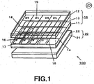
- the present invention is applied to, e.g., a color liquid crystal display apparatus 100 of the backlight system of the configuration as shown in FIG 1 .
- the color liquid crystal apparatus 100 shown in FIG. 1 comprises the transmission type color liquid crystal display panel 10, and a backlight unit 20 provided at the rear face side of the color liquid crystal display panel 10.
- the transmission type color liquid crystal display panel 10 has the configuration in which a TFT base (substrate) 11 and an opposite electrode base (substrate) 12 are arranged opposite to each other, and a liquid crystal layer 13 in which, e.g., twisted nematic (TN) liquid crystal is filled is provided at the spacing therebetween.
- a TFT base substrate
- an opposite electrode base substrate
- a liquid crystal layer 13 in which, e.g., twisted nematic (TN) liquid crystal is filled is provided at the spacing therebetween.
- signal lines 14 and scanning lines 15 which are arranged in a matrix form
- thin film transistors 16 as switching elements and pixel electrodes 17 which are arranged at intersecting points thereof.
- the thin film transistors 16 are sequentially selected by the scanning lines 15, and serve to write video signals delivered from the signal lines 14 into corresponding pixel electrodes 17.
- opposite electrodes 18 and color filters 19 are formed at the internal surface of the opposite electrode base 12.
- the color liquid crystal display apparatus 100 is adapted so that the transmission type color liquid crystal display panel 10 of such a configuration is put between two polarization plates to perform drive operation by the active matrix system in the state where white light is irradiated from the rear face side by the backlight unit 20 so that a desired full color image display can be obtained.
- the backlight unit 20 comprises a light source 21 and a waveform length selection filter 22.
- the backlight unit 20 serves to irradiate rays of light which have been emitted from the light source 21 to illuminate the color liquid crystal display panel 10 through the wavelength selection filter 22 from the rear face side thereof.
- the color liquid crystal display apparatus 100 to which the present invention is applied is driven by, e.g., a drive circuit 200 of which electric block configuration is shown in FIG. 2 .
- the drive circuit 200 comprises a power supply unit 110 for delivering drive powers of the color liquid crystal display panel 10 and the backlight unit 20, an X-driver circuit 120 and a Y-driver circuit 130 which are adapted for driving the color liquid crystal display panel 10, a RGB process processing unit 150 supplied with a video signal through an input terminal 140 from the external, an image memory 160 and a control unit 170 which are connected to the RGB process processing unit 150, and a backlight drive control unit 180 for performing drive control of the backlight unit 20.
- a power supply unit 110 for delivering drive powers of the color liquid crystal display panel 10 and the backlight unit 20
- an X-driver circuit 120 and a Y-driver circuit 130 which are adapted for driving the color liquid crystal display panel 10
- a RGB process processing unit 150 supplied with a video signal through an input terminal 140 from the external
- an image memory 160 and a control unit 170 which are connected to the RGB process processing unit 150
- a backlight drive control unit 180 for performing drive control of the backlight unit 20.
- video signal Vi which has been inputted through the internal terminal 140 is caused to undergo signal processing such as chroma processing, etc. by the RGB process processing unit 150. Further, the video signal Vi thus processed is converted from composite signal into RGB separate signal suitable for drive operation of the color liquid crystal display panel 10.
- the RGB separate signal thus obtained is delivered to the control unit 170 and is delivered to the X-driver 120 through the image memory 160.
- the control unit 170 controls the X-driver circuit 120 and the Y-driver circuit 130 at a predetermined timing corresponding to the RGB separate signal to drive the color liquid crystal display panel 10 by RGB separate signal delivered to the X-driver 120 through the image memory 160 to display an image corresponding to the RGB separate signal.
- the backlight unit 20 is of immediately below illumination type in which the transmission type color liquid crystal display panel 10 is disposed at the rear face thereof and serves to illuminate the color liquid crystal from the portion immediately below the rear face.
- the light source 21 of the backlight unit 20 includes plural LEDs (Light Emitting Diodes) and uses these plural light emitting diodes as light emitting source.
- the plural light emitting diodes are divided into set comprised of groups of light emitting diodes, and are driven every those sets.
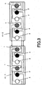
- FIG 3 shows the state where, as arrangement example of light emitting diodes, two light emitting diodes 1 of red, two light emitting diodes 2 of green and two light emitting diodes 3 of blue are respectively used every unit cells 4-1, 4-2 so that six light emitting diodes in total are arranged in line.
- distribution of the number of respective colors may be variation except for this example from the necessity of adjusting the light output balance because mixed color is caused to be white light having good balance by rating and/or light emission efficiency of light emitting diodes used, etc.
- FIG 3 shows the unit cell 4-1 and the unit cell 4-2 in the arrangement example shown in FIG 3 , the unit cell 4-1 and the unit cell 4-2 have entirely the same configuration, and are connected at the central both end portions indicated by arrow.
- FIG 4 shows the example in which the form where the unit cell 4-1 and the unit cell 4-2 are connected is illustrated by diode mark of the electric circuit diagram symbol.
- respective light emitting diodes i.e., light emitting diodes 1 of red, light emitting diodes 2 of green and light emitting diodes 3 of blue are connected in series in the state where they have polarities conforming to a direction where current flows from the left to the right.
- (2G 2R 2B) shows that six patterns in total consisting of two patterns for green, two patterns for red and two patterns for blue are caused to be elementary unit.
- (6G 6R 6B) shows that six patterns in total consisting of two patterns for green, two patterns for red and two patterns for blue are caused to be elementary unit.
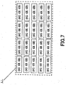
- the elementary unit which is three times larger than the previously described elementary unit (2G 2R 2B) of light emitting diodes is caused to be one middle unit (6G 6R 6B) so that the middle units (6G 6R 6B) are arranged in a matrix form having five rows in a horizontal direction and four columns in a vertical direction with respect to the screen.
- 360 light emitting diodes in total are arranged.
- These middle units (6G 6R 6B) are electrically connected in a screen horizontal direction so that light emitting diodes arranged in the screen horizontal direction.
- the middle units (6G 6R 6B) are electrically connected in the screen horizontal direction are connected in series, as shown in FIG. 8 , at the light source 21 of the backlight unit 20.
- plural groups 30 of plural light emitting diodes which are connected in series in a horizontal direction are formed.
- independent LED drive circuits 31 are respectively provided one by one at individual groups 30 of light emitting diodes which are connected in series in horizontal direction.
- the LED drive circuit 31 is a circuit for allowing current to flow in the group 30 of light emitting diodes to emit them.
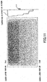
- FIG. 9 shows the region where the portion in which hatching is thick has high temperature, and shows the region where the portion in which hatching is thin has low temperature.
- temperature becomes high according as distance from the picture upper portion Su decreases, temperature becomes higher, and the screen lower portion Sd has low temperature.
- FIG. 10 is a view in which the diagram indicating the connection relationship of light emitting diodes of FIG. 8 and the temperature distribution diagram of FIG 9 overlap with each other. As shown in FIG 10 , in this example, when light emitting diodes arranged in a horizontal direction of the screen are connected, light emitting diodes having substantially the same temperature are connected to each other.
- thermosensor 32 for detecting temperatures of the groups of respective light emitting diodes 30.
- the temperature sensor 32 As the temperature sensor 32, as shown in FIG. 10 , there may be provided plural LEDs at respective vertical positions corresponding to the groups of light emitting diodes which are connected in series in a horizontal direction, or only one LED may be provided at one backlight unit 20. Moreover, as shown in FIG. 11 , for example, the backlight unit 20 may be caused to be of the configuration in which one temperature sensor 32 and a memory within which temperature distribution pattern in the screen vertical direction is stored in advance, e.g., memory 49 which will be described later are provided at the screen center to estimate temperatures at respective positions in the screen vertical direction by making reference to the content from detection value of one temperature sensor 32. Temperature values detected by the temperature sensors 32 are delivered to the LED drive circuit 32 for driving corresponding group of light emitting diodes.
- light quantity or chromaticity sensors 33 (33R, 33G, 33B) for detecting light quantities or chromaticities of respective colors of R, G, B of the respective groups of light emitting diodes 30.
- plural light quantity or chromaticity sensors 33 are provided at respective vertical positions corresponding to the groups 30 of light emitting diodes which are connected in series in a horizontal direction.
- an optical system in which a diffusion plate for permitting the entire color mixture to be uniform, etc. is utilized to effectively perform color mixing of rays of light emitted of individual LEDs, and the like to allow the number of light quantity or chromaticity sensors 33 (33R, 33G, 33B) to be one.
- the characteristic of the light quantity or chromaticity sensor 33 is calculated by optical simulation or actual measurement by the reference light emitting diode, etc. to prepare the correction value data thereof as memory table in advance to correct sensed light quantity data on the basis of correction value data, thus making it possible to comply with such situation or inconvenience.
- the LED drive circuit 31 for driving groups of light emitting diodes 30 which are connected in series in a horizontal direction will be explained.
- the LED drive circuit 31 is provided within backlight drive control unit 180.
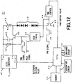
- a circuit configuration example of the LED drive circuit 31 is shown in FIG. 12 .
- the LED drive circuit 31 comprises a DC-DC converter 41, a constant resistor (Rc) 42, a FET 43, a PWM control circuit 44, a capacitor 45, a FET 46 for sample hold, a resistor 47, a hold timing circuit 48, a memory 49, and a CPU (Central Processing Unit) 50.
- the LED drive circuit 31 is supplied with detection output values of the temperature sensor or sensors 32, and the light quantity or chromaticity sensors 33 (33R, 33G, 33B).
- the DC-DC converter 41 is supplied with DC voltage V IN generated from the light source 110 shown in FIG 2 to perform switching operation of inputted DC power to generate a stabilized DC output voltage Vcc.
- the DC-DC converter 41 generates a stabilized output voltage Vcc so that potential difference between voltage inputted from feedback terminal Vf and output voltage Vcc becomes equal to reference voltage value (Vref).
- reference voltage value (Vref) is delivered from the CPU 50.
- the anode side of the group of light emitting diodes 30 which are connected in series is connected to the output terminal for output voltage Vcc of the DC-DC converter 41 through constant resistor (Rc). Moreover, the anode side of the group of light emitting diodes 30 which are connected in series is connected to the feedback terminal of the DC-DC converter 41 through source-drain of the sample-hold FET 46. Further, the cathode side of the group of light emitting diodes 30 which are connected in series is connected to the ground through the portion (channel) between source and drain.
- the gate of the FET 43 is supplied with PWM signal which has been generated from the PWM control circuit 44.
- PWM signal When PWM signal is in ON state, the portion (channel) between the source and the drain of the FET 43 is turned ON.
- the PWM signal When the PWM signal is in OFF state, the portion (channel) between source and drain is tuned OFF. Accordingly, when the PWM signal is in ON state, the FET 43 allows current to flow in the groups of light emitting diodes 30.
- the PWM signal is in OFF state, the FET 43 allows current flowing in the group of light emitting diodes 30 to be zero. Namely, when the PWM signal is in ON state, the FET 43 emits the group of light emitting diodes 30.
- the PWM signal When the PWM signal is in OFF state, the FET 43 stops emitting operation of light emission of the groups of light emitting diodes 30.
- the PWM control circuit 44 generates a PWM signal which is binary signal in which duty ratio between ON time and OFF time is adjusted.
- the PWM control circuit 44 is supplied with a PWM control value from the CPU 50 to change duty ratio in accordance with the PWM control value.
- the capacitor 45 is provided between the output terminal of the DC-DC converter 41 and the feedback terminal thereof.
- the resistor 47 is connected to the output terminal of the DC-DC converter 41 and the gate of the sample-hold FET 46.
- the hold timing circuit 48 is supplied with a PWM signal to generate a hold signal which is turned OFF only for a predetermined time period at rising edge of the PWM signal and which is turned ON at other times.
- the gate of the sample-hold FET 46 is supplied with a hold signal which has been outputted from the hold timing circuit 48.
- the hold signal is in OFF state, the portion (channel) between the source and the drain of the sample hold FET 46 is turned ON.
- the hold signal is in ON state, the portion (channel) between the source and the drain of the sample-hold FET 46 is turned OFF.
- current I LED is caused to flow in the group of light emitting diodes 30 only for a time period during which PWM signal generated from the PWM control circuit 44 is in ON state.
- the capacitor 45, the sample-hold FET 46 and the resistor 47 constitute sample-hold circuit.
- the sample-hold circuit serves to sample, at the time when the PWM signal is in ON state, voltage value of the anode of the group of light emitting diodes 30, i.e., one end of the constant resistor 42 in which output voltage Vcc is not applied to deliver the voltage value thus sampled to the feedback terminal of the DC-DC converter 41. Since the DC-DC converter 41 stabilizes output voltage Vcc on the basis of voltage value inputted to the feedback terminal, crest (peak) value of current I LED flowing in the constant resistor Rc 42 and the group of light emitting diodes 30 becomes constant.
- pulse drive operation corresponding to the PWM signal is performed in the state where crest (peak) value of current I LED flowing in the group 30 of light emitting diodes 30 is caused to be constant.
- the CPU 50 serves to adjust current quantities flowing in the groups of light emitting diodes 30, on the basis of both detection signals of the temperature sensor or sensors 32 and the light quantity or chromaticity sensors 33 (33R, 33G, 33B), so that color tone (color temperature and chromaticity) and luminance of white light emitted from the backlight unit 20 become constant.
- Adjustment of current values flowing in the group of light emitting diodes 30 may be performed by changing PWM control value to adjust duty of current flowing in the group of light emitting diodes 30, may be performed by changing reference voltage value (Vref) delivered to the DC-DC converter 41 to adjust crest (peak) value of current flowing in the group of light emitting diodes 30, or may be performed by combination of these adjustment methods.
- Vref reference voltage value
- the CPU 50 performs feedback control of intensity of rays of light emission of the group of light emitting diodes 30 on the basis of both detection signals of the temperature sensor or sensors 32 and light quantity or chromaticity sensors 33 (33R, 33G, 33B), thus making it possible to generate white light having uniform chromaticity and luminance within the image.
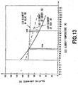
- FIG. 13 is a view showing relative luminance values of respective LED elements of red (R), green (G) and blue (B).
- LED element temperature is indicated in the x-axis direction
- relative luminance is indicated in the y-axis direction
- the point of element temperature 25°C is caused to be relative luminance 100%.
- the LED element of red (R) has the semiconductor layered structure of four element system of AlInGaP. Since the band gap energy is low, carriers contribution to light emission decrease at the time of high temperature. Thus, light quantity emitted is lowered. As a result, in the state of about 70°C which is general as running (operating) temperature of LED element, luminance value is lowered down to about 60% when 25°C is set as normal temperature. Moreover, in the LED element of red (R), change of luminance value with respect to temperature is large as compared to other colors.
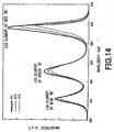
- FIG 14 is a graph showing brightness with respect to light emission wavelengths of respective LED elements of red (R), green (G) and blue (B). Graphs with respect to respective cases where temperature is 0°C, 25°C and 50°C are shown in FIG. 14 .
- light emission wavelength is indicated in the x-axis direction
- light emission output is indicated in the y-axis direction.
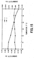
- FIG 15 shows temperature deviation of white chromaticity (CIE chromaticity coordinate display (x, y)) when rays of light emitted from LED element of red (R), LED element of green (G) and LED element of blue (B) which have the above-described characteristic are combined to optically perform synthetic additive color mixture at the backlight unit 20 to obtain white light.
- the characteristic shown in FIG 15 is measured in the state where feedback control of temperature and light quantity based on chromaticity sensor is stopped.
- chromaticity of white light has the deviation that deviation of Y ( ⁇ y value) becomes equal to +0.0025 and deviation of X ( ⁇ x value) becomes equal to -0.015.
- the chromaticity of white color is in correspondence with the tendency where wavelength corresponding to mountain-shaped summit point (peak) (peak wavelength) shifts towards long wavelength side according as temperature rises in the characteristic with respect to temperature change of LED element of red (R) shown in FIG 14 .
- the LED elements have temperature characteristic as stated above.
- Such LED elements have large temperature dependency and have their characteristics varying depending upon colors. For this reason, the CPU 50 is required to perform a control also by using the temperature sensor 32 in order to allow color tone (color temperature and chromaticity) of white light emitted from the backlight unit 20 to be constant.
- the CPU 50 is required to detect, by light quantity sensors, respective light emission quantities of respective colors of red (R), green (G) and blue(B) to synthetically control light emission quantities of red (R), green (G) and blue (B). Namely, there is not employed an approach to perform feedback control of light emission quantity of red (R) by making reference to only light quantity sensor output for red (R), but it is required to perform feedback control of light emission quantity of red (R) by making reference to light quantity sensor outputs of all colors (red (R), green (G) and blue (B)) also including other colors.
- the CPU 50 performs operation (calculation) on the basis of matrix operational expression having three rows and three columns as indicated by the following formula (1) to synthetically adjust light emission quantities of LED elements of respective colors (R, G, B).
- X Y Z m 11 m 12 m 13 m 21 m 22 m 23 m 31 m 32 m 33
- X", “Y” and “Z” represent chromaticity coordinates of rays of light emitted from the backlight unit 20.
- “Lr” indicates detection output value of red component of the light quantity or chromaticity sensor 33
- “Lg” indicates detection output value of green component of the light quantity or chromaticity sensor 33
- “Lb” indicates detection output value of blue component of the light quantity or chromaticity sensor 33.
- matrix A consisting of coefficients m xy of three rows, ⁇ three columns which is preceding matrix of the right side of the formula (1) is matrix of coefficients multiplied by detection output values (Lr, Lg, Lb) of the light quantity or chromaticity sensor 33.
- detection output values Lr, Lg, Lb
- subscript x of m is 1, 2, 3 and indicates row number of coefficient corresponding thereto
- subscript y thereof is 1, 2, 3 and indicates column number of coefficient corresponding thereto.
- the matrix A should be expressed as constant when considered ideally.
- the matrix A results in matrix obtained by multiplying matrix C represented by constant j xy of three rows ⁇ three columns and matrix B of function k xy (T) using, as parameter, temperature T of LED element for canceling the temperature characteristic.
- m 11 m 12 m 13 m 21 m 22 m 23 m 31 m 32 m 33 j 11 j 12 j 13 j 21 j 22 j 23 j 31 j 32 j 33
- the CPU 50 performs, on the basis of the formula (1), by using detection output (T) of temperature sensor 32 along with detection outputs (Lr, Lg, Lb) of the light quantity or chromaticity sensor 33, a feedback control such that color tone (color temperature and chromaticity) of white light becomes constant.
- function k xy (T) values which are components of the matrix B and coefficient j xy values which are components of the matrix C are calculated in advance by experiment or measurement before shipping or forwarding from factory, and are stored in memory 49 which is non-volatile memory.
- the CPU 50 performs, at a suitable time period (e.g., every predetermined time period, or at all times) an adjustment control of chromaticity and luminance of the backlight unit 20.
- the CPU 50 When the CPU 50 starts the adjustment control of chromaticity and luminance of the backlight unit 20, it reads out outputs of the temperature sensor or sensors 32 and the light quantity or chromaticity sensors 33, and calls (reads out) the function k xy and the coefficient j xy from the memory 49.
- the CPU 50 is operative to substitute temperature or temperatures which has or have been detected by the temperature sensor or sensors 32 into T of the above-mentioned formulas (1) and (2), and to substitute detection values of the light quantity or chromaticity sensors 33 into Lr, Lg, Lb of the above-mentioned formulas (1) and (2) to calculate chromaticities (X, Y, Z) of respective colors of the backlight unit 20.
- the CPU 50 adjusts current value (PWM duty or crest value) caused to flow in LED elements of respective colors so that the chromaticities (X, Y, Z) thus calculated become equal to values stored in the memory 49, etc. in which specific set values, e.g., ideal values are set before shipping or forwarding from factory.
- the CPU 50 permits color tone (color temperature and chromaticity) of white light emitted from the backlight unit 20 to be constant at all times.
- FIG 16A is a view showing temperature deviation of chromaticity (CIE chromaticity coordinate display (x, y)) of white light emitted from the backlight unit 20 in the case where chromaticity control is performed only by the light quantity or chromaticity sensor 33 without performing feedback control by the temperature sensor 32 (the case of the conventional method).
- FIG 16B is a view showing temperature deviation of chromaticity (CIE chromaticity coordinate display (x, y)) of white light emitted from the backlight unit 20 in the case where feedback control by both the temperature sensor 32 and the light quantity or chromaticity sensor 33 is performed to perform chromaticity control (the case of the method of the present invention).
- ⁇ y value is +0.0010 and ⁇ x value is -0.0015 as deviation within the range from 25°C to 50°. It is understood that this characteristic is improved by 1/5 in terms of ⁇ y value and by 1/10 in terms of ⁇ x value as compared to the characteristic shown in FIG. 15 .
- ⁇ y value is +0.0005 and ⁇ x value is -0.0005 as deviation within the range from 25°C to 50°C. It is understood that this characteristic is improved by 1/2 in terms of ⁇ y value and by 1/3 in terms of ⁇ x value as compared to the characteristic shown in FIG. 15 so that further characteristic improvement is performed.
- color tone color temperature and chromaticity
- luminance of white light to be emitted are caused to be constant on the basis of both detection signals of the temperature sensor or sensors 32 and the light quantity or chromaticity sensors 33 (33R, 33G, 33B), it is possible to emit rays of light of stable color tone with high accuracy.
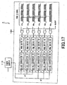
- the backlight drive control unit 180 comprises the above-described plural LED drive circuits 31 supplied with voltage from power supply 110 for converting AC voltage into DC voltage to drive the groups of light emitting diodes 30.
- the group of g1 indicates group of the uppermost row composed of group of light emitting diodes 30 of red (R1), group of light emitting diodes 30 of green (G1) and group of light emitting diodes of blue (B1).
- the group of g2 indicates the group of row located below by one row relative to the group g1 composed of group of light emitting diodes 30 of red (R2), group of light emitting diodes 30 of green (G2) and group of light emitting diodes 30 of blue (B2).
- FIG 14 shows, in a model form, difference between drive widths when PWM signal is delivered to the group of light emitting diodes 30 of respective rows.
- LED element of red Since the LED element of red (R) has good light luminous efficacy, ON time period of the PWM signal is shortened as compared to the LED element of blue (B). Moreover, difference k between drive widths of PWM signal of R1p of g1 row and PWM signal of R2p of g2 row is large. This is because since g1 row is located above the display relative to g2 row so that temperature is high and LED element to which attention is drawn is LED element of red (R) having large light emission quantity change by temperature dependency, it is necessary to allow drive width to be varied.
- the backlight drive control unit 180 performs drive operation such that pulse width of the PWM signal becomes large, in order to realize light quantity balance with respect to groups of other rows, at g1 row where temperature is high.
- the backlight drive control unit 180 is adapted so that difference of ON time period of PWM signal is used as a technique for changing light emission quantity in order to allow temperature distribution of the display to be uniform, thus making it possible to ensure uniformity of temperature characteristic within the display.
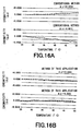
- FIG. 18 is a waveform diagram showing resolution of PWM signal.
- FIG. 18A shows waveform diagram of PWM signal delivered to the group of light emitting diodes 30 of red (R)
- FIG. 18B shows a waveform diagram of PWM signal delivered to the group of light emitting diodes 30 of green (G)
- FIG. 18(C) shows a waveform diagram of PWM signal delivered to the group of light emitting diodes 30 of blue (B).
- a predetermined white light can be obtained, as shown in FIG. 18 , at the time of mixture ratio where pulse width of PWM signal delivered to the group of light emitting diodes 30 of blue (B) is 256 (100%), pulse width of PWM signal delivered to the group of light emitting diodes 30 of green (G) is 191 (about 75%), and pulse width of PWM signal of the group of light emitting diodes 30 of red (R) is 126 (50%).
- the degree of freedom of pulse width of PWM signal delivered to the group of light emitting diodes 30 of blue (B) can be adjusted by 1/256 Step as shown in FIG. 18 .
- the degree of freedom of adjustment width of pulse width of PWM signal delivered to the group of light emitting diodes 30 of red (R) can be only adjusted by 1/126 Step which is about one half thereof.
- the backlight drive control unit 180 adjusts crest (peak) value of a signal (constant current value ILED) delivered from the DC-DC converter to the respective groups of light emitting diodes 30 so that adjustment widths of PWM signals delivered to respective groups of light emitting diodes 30 are substantially uniform (e.g., 8 bits).
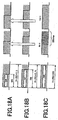
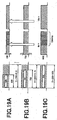
- the waveform diagram of PWM signal delivered to the group of light emitting diodes 30 of red (R) is shown in FIG. 19A
- the waveform diagram of PWM signal delivered to the group of light emitting diodes 30 of green (G) is shown in FIG 19B
- the waveform diagram of PWM signal delivered to the group of light emitting diodes 30 of blue (B) is shown in FIG. 19C .
- the backlight drive control unit 180 performs PAM (Pulse Amplitude Modulation) of signals delivered from, e.g., DC-DC converter to respective groups of light emitting diodes 30 to adjust crest (peak) value of constant current value ILED delivered to respective groups of light emitting diodes 30. Accordingly, the backlight drive control unit 180 performs adjustments in time direction and in direction of crest value with respect to signals to be delivered to respective groups of light emitting diodes 30 to ensure accuracy at the time of adjustment, thus making it possible to maintain balance of adjustment accuracy of the respective groups of light emitting diodes 30.
- PAM Pulse Amplitude Modulation
- FIG 20A shows signal waveform in the case where a signal in time direction is modulated (PWM is performed), and a signal in amplitude direction is not changed (fixed), i.e., peak current of LED element is not changed.
- FIG. 20C shows a signal waveform in the case where signal in the time direction (in the PWM direction) is fixed, and signal only in amplitude direction is modulated.
- FIG 20B shows a signal waveform in the case where a signal in time direction is modulated and a signal in amplitude direction is also modulated.
- the backlight drive control unit 180 performs modulation in a time direction (PWM), and modulation in an amplitude direction (PAM) may be performed for correction of light emission output balance by temperature distribution of display.
- PWM time direction
- PAM amplitude direction
- the backlight drive control unit 180 In adjusting light emitting operation of the groups of light emitting diodes 30 constituting the backlight unit 2, the backlight drive control unit 180 according to the invention of this Application constituted in this way performs adjustments in the amplitude direction and in the time direction so that resolutions of adjustment become uniform in all of the groups of light emitting diodes 30 of respective colors.
- the backlight drive control unit 180 suitably detects temperature distribution extending from the upper portion of the display toward the lower portion thereof to perform adjustment in the amplitude direction on the basis of the detection results to perform peak control of current values delivered to the groups of light emitting diodes 30, it is possible to eliminate display unevenness by temperature distribution of the display.
Landscapes
- Engineering & Computer Science (AREA)
- Physics & Mathematics (AREA)
- Computer Hardware Design (AREA)
- General Physics & Mathematics (AREA)
- Theoretical Computer Science (AREA)
- Liquid Crystal (AREA)
- Circuit Arrangement For Electric Light Sources In General (AREA)
- Led Devices (AREA)
- Liquid Crystal Display Device Control (AREA)
Claims (12)
- Ansteuerungseinrichtung (180) für eine Hintergrundbeleuchtungseinheit (20), die mehrere Gruppen von LED(Light Emitting Diode)-Elementen (30) umfasst, wobei die mehreren LED-Elemente in Reihe geschaltet sind und jede drei Primärfarben in verschiedenen Teilen (4, 4-1, 4-2) angeordnet sind,
wobei die Ansteuerungseinrichtung (180) Folgendes umfasst:unabhängige LED-Ansteuerungsschaltungen (31), die jeweils einzeln an einzelnen Gruppen (30) von Leuchtdioden bereitgestellt sind;ein Signalerzeugungsmittel (50), das funktionsfähig ist, ein Lichtemissionssignal der Gruppen der LED-Elemente zu erzeugen;ein Ansteuerungsmittel (43), das funktionsfähig ist, die Gruppen der LED-Elemente (30) auf der Basis des Signals, das von dem Signalerzeugungsmitteln (50) erzeugt wurde, anzusteuern;ein Spannungsanlegemittel (41), das funktionsfähig ist, eine Spannung an die Gruppen der LED-Elemente (30) anzulegen;ein Lichtemissionsquantitätsdetektionsmittel (33), das funktionsfähig ist, Quantitäten von Lichtstrahlen, die von den Gruppen der LED-Elemente, an die die Spannung angelegt wurde, emittiert werden, zu detektieren;ein Temperaturdetektionsmittel (32), das funktionsfähig ist, eine Temperatur oder Temperaturen der Gruppen der LED-Elemente zu detektieren; undein Steuerungsmittel (44), das funktionsfähig ist, das Ansteuerungsmittel (43) zu steuern, so dass eine Lichtemissionsausgabe in Übereinstimmung mit den jeweiligen Gruppen der LED-Elemente (30) gesteuert wird, die auf der Basis von Lichtemissionsquantitäten, die von dem Lichtemissionsquantitätsdetektionsmittel detektiert wurden, und der Temperatur oder den Temperaturen, die von dem Temperaturdetektionsmittel (32) detektiert wurde oder wurden, angeordnet wurden,ein Amplitudenanpassungsmittel (48) zum Anpassen der Amplitude eines konstanten Stromwertes, der in den Gruppen der LED-Elemente (30) fließt, in Übereinstimmung mit der Temperatur oder den Temperaturen, die von dem Temperaturdetektionsmittel (32) detektiert wurde oder wurden,
wobei das Steuerungsmittel (44) funktionsfähig ist, das Amplitudenanpassungsmittel (48) zusammen mit dem Signalerzeugungsmittel (150), das mit diesem zur Steuerung einer Lichtemissionsausgabe der Gruppen der LED-Elemente (30) verbunden ist, zu steuern, wobei das Amplitudenanpassungsmittel (48) eine Pulsamplitudenmodulation durchführt, um eine Spitze des konstanten Stromwerts so anzupassen, dass Anpassungsbreiten von pulsbreitenmodulierten Signalen, die an jeweilige Gruppen von LEDs (30) übertragen werden, im Wesentlichen gleichförmig sind,
wobei das Amplitudenanpassungsmittel (48) die Pulsamplitudenmodulation durchführt, um eine Lichtemissionsausgabeabgleichvariation in Abhängigkeit von der Temperatur oder den Temperaturen zu korrigieren, und das Signalerzeugungsmittel (50) die Pulsbreitenmodulation durchführt, so dass ein Weißabgleich angepasst wird. - Ansteuerungseinrichtung nach Anspruch 1, wobei die jeweiligen Gruppen der LED-Elemente (30) so ausgelegt sind, dass die mehreren in Reihe geschalteten LED-Elemente in einer horizontalen Richtung angeordnet sind.
- Ansteuerungseinrichtung nach Anspruch 1, wobei das Lichtemissionsquantitätsdetektionsmittel (33) Quantitäten von Lichtstrahlen detektiert, die von den Gruppen der LED-Elemente (30), die aus den LED-Elementen von beliebigen Primärfarben bestehen, emittiert wurden.
- Ansteuerungseinrichtung nach Anspruch 1, die Folgendes beinhaltet:einen Speicher (49) zum Speichern von Korrektionsdaten, die dem Korrigieren von Lichtquantitäten von von den LED-Elementen (30) emittierten Lichtstrahlen, die von dem Lichtemissionsquantitätsdetektionsmittel (33) detektiert wurden, in Übereinstimmung mit einem Teil, in dem die LED-Elemente (30) angeordnet sind, dienen,wobei das Steuerungsmittel (44) das Signalerzeugungsmittel (50) auf der Basis der Lichtemissionsquantitäten, die durch die in dem Speicher (40) gespeicherten Korrektionsdaten korrigiert wurden, und der Temperatur oder den Temperaturen, die von dem Temperaturdetektionsmittel (32) detektiert wurde oder wurden, steuert.
- Ansteuerungseinrichtung nach Anspruch 1, die Folgendes umfasst:eine Speichertabelle, in der Korrektionswertdaten, die durch ein vorbestimmtes Verfahren zur tatsächlichen Messung erhalten wurden, gespeichert sind,wobei das Steuerungsmittel (44) Lichtemissionsquantitäten, die von dem Lichtemissionsquantitätsdetektionsmittel (33) detektiert wurden, auf der Basis von Korrektionswertdaten, die in der Speichertabelle gespeichert sind, korrigiert, um das Signalerzeugungsmittel (50) auf der Basis von korrigierten Lichtemissionsquantitäten und von Temperatur oder Temperaturen, die von dem Temperaturdetektionsmittel (32) detektiert wurde oder wurden, zu steuern.
- Ansteuerungseinrichtung nach Anspruch 1, die Folgendes umfasst:Lichtquantitätsverhältnisanpassungsmittel zum geeigneten Anpassen eines Lichtquantitätsverhältnisses der jeweiligen LED-Elemente (30), und eine Speichertabelle, in der Temperaturinformationen einer beliebigen einzigen Farbe, die bestimmt ist, eine Referenz beim Erhalten von Weißlicht durch das Lichtquantitätsverhältnisanpassungsmittel zu sein, und Korrektionswertdaten, die durch ein vorbestimmtes Verfahren zur tatsächlichen Messung erhalten wurden, gespeichert sind,wobei das Steuerungsmittel (44) Lichtemissionsquantitäten, die von dem Lichtemissionsquantitätsdetektionsmittel (33) detektiert wurden, auf der Basis von Korrektionswertdaten, die in der Speichertabelle gespeichert sind, korrigiert, um das Signalerzeugungsmittel (50) auf der Basis von korrigierten Lichtemissionsquantitäten und von einer Temperatur oder Temperaturen, die von dem Temperaturdetektionsmittel (32) detektiert wurde oder wurden, zu steuern.
- Ansteuerungsverfahren für eine Hintergrundbeleuchtungseinheit, in der mehrere Gruppen von LED(Light Emitting Diode)-Elementen (30), wobei die mehreren LED-Elemente in Reihe geschaltet sind und jede drei Primärfarben in verschiedenen Teilen angeordnet sind,
wobei das Ansteuerungsverfahren Folgendes umfasst:einen Spannungsanlegeschritt des Anlegens einer Spannung an jede der Gruppen der LED-Elemente;einen Lichtemissionsquantitätsdetektionsschritt des Detektierens von Quantitäten von Lichtstrahlen, die von den Gruppen der LED-Elemente (30), an die die Spannung durch den Spannungsanlegeschritt angelegt wurde, emittiert werden;einen Temperaturdetektionsschritt des Detektierens von einer Temperatur oder Temperaturen der Gruppen der LED-Elemente (30);einen Signalerzeugungsschritt des Erzeugens eines Lichtemissionssignals der Gruppen der LED-Elemente (30) auf der Basis von Lichtemissionsquantitäten, die durch den Lichtemissionsquantitätsdetektionsschritt detektiert wurden, und von einer Temperatur oder Temperaturen, die durch den Temperaturdetektionsschritt detektiert wurde oder wurden;einen Steuerungsschritt des Steuerns einer Lichtemissionsausgabe in Übereinstimmung mit den jeweiligen mehreren Gruppen der LED-Elemente (30), die auf der Basis des Lichtemissionssignals, das durch den Signalerzeugungsschritt erzeugt wurde, angeordnet wurden,Anpassen der Amplitude eines konstanten Stromwertes, der in den Gruppen der LED-Elemente fließt, in Übereinstimmung mit der Temperatur oder den Temperaturen, die detektiert wurde oder wurden; undSteuern der Lichtemissionsausgabe der Gruppen von LED-Elementen durch Steuern von sowohl der Amplitude des konstanten Stromwertes als auch dem Tastgrad des Pulsbreitenmodulationssignals,wobei der Schritt des Anpassens der Amplitude eine Pulsamplitudenmodulation durchführt, um eine Spitze des konstanten Stromwertes so anzupassen, dass Anpassungsbreiten von pulsbreitenmodulierten Signalen zu jeder der primärfarbigen LEDs im Wesentlichen gleichförmig sind,
wobei die Pulsamplitudenmodulation einen Lichtemissionsausgabeabgleich in Abhängigkeit von der Temperatur oder den Temperaturen korrigiert und die Pulsbreitenmodulation zum Anpassen eines Weißabgleichs verwendet wird. - Ansteuerungsverfahren nach Anspruch 7,
wobei die jeweiligen Gruppen der LED-Elemente so ausgelegt sind, dass die mehreren in Reihe geschalteten LED-Elemente (30) in einer horizontalen Richtung angeordnet sind, und
eine Lichtemissionsausgabe in Übereinstimmung mit den jeweiligen Gruppen der LED-Elemente (30) in dem Steuerungsschritt gesteuert wird. - Ansteuerungsverfahren nach Anspruch 7, wobei Quantitäten von Lichtstrahlen, die von den Gruppen von LED-Elementen (30), die aus den LED-Elementen von beliebigen Primärfarben zusammengesetzt sind, erzeugt wurden, in dem Lichtemissionsquantitätsdetektionsschritt detektiert werden.
- Ansteuerungsverfahren nach Anspruch 7, das Folgendes umfasst:einen Korrektionsschritt des Korrigierens der Lichtemissionsquantitäten der LED-Elemente (30), die durch den Lichtemissionsquantitätsdetektionsschritt detektiert wurden, in Übereinstimmung mit einem Teil, in dem die LED-Elemente (30) angeordnet sind, so dass dementsprechend in dem Signalerzeugungsschritt das Lichtemissionssignal auf der Basis der Lichtemissionsquantitäten, die durch den Korrektionsschritt korrigiert wurden, und von einer Temperatur oder Temperaturen, die durch den Temperaturdetektionsschritt detektiert wurde oder wurden, erzeugt wird.
- Ansteuerungsverfahren nach Anspruch 7, das Folgendes umfasst:einen Korrektionsschritt des Korrigierens von Lichtemissionsquantitäten, die von Sensoren zum Detektieren von Quantitäten von Lichtstrahlen, die von den Gruppen der LED-Elemente (30) emittiert werden, in dem Lichtemissionsdetektionsschritt erhalten wurden, auf der Basis von Korrektionswertdaten einer Speichertabelle, in der Korrektionswertdaten, die durch ein vorbestimmtes Verfahren zur tatsächlichen Messung erhalten wurden, gespeichert sind,wobei das Lichtemissionssignal in dem Signalerzeugungsschritt auf der Basis von Lichtemissionsquantitäten, die durch den Korrektionsschritt korrigiert wurden, und von einer Temperatur oder Temperaturen, die durch den Temperaturdetektionsschritt detektiert wurde oder wurden, erzeugt wird.
- Ansteuerungsverfahren nach Anspruch 7, das Folgendes umfasst:einen Lichtquantitätsverhältnisanpassungsschritt des geeigneten Anpassens eines Lichtquantitätsverhältnisses der LED-Elemente der jeweiligen Farbe; und einen Korrektionsschritt des Korrigierens von Lichtemissionsquantitäten, die durch den Lichtemissionsdetektionsschritt detektiert wurden, auf der Basis einer Speichertabelle, in der Temperaturinformationen einer beliebigen einzigen Farbe, die bestimmt ist, eine Referenz beim Erhalten von Weißlicht durch denLichtquantitätsverhältnisanpassungsschritt zu sein, und Korrektionswertdaten, die durch ein vorbestimmtes Verfahren zur tatsächlichen Messung erhalten wurden, gespeichert sind,wobei das Lichtemissionssignal in dem Signalerzeugungsschritt auf der Basis von Lichtemissionsquantitäten, die durch den Korrektionsschritt korrigiert wurden, und von einer Temperatur oder Temperaturen, die durch den Temperaturdetektionsschritt detektiert wurde oder wurden, erzeugt wird.
Applications Claiming Priority (3)
| Application Number | Priority Date | Filing Date | Title |
|---|---|---|---|
| JP2004205146 | 2004-07-12 | ||
| JP2004336373 | 2004-11-19 | ||
| PCT/JP2005/012686 WO2006006537A1 (ja) | 2004-07-12 | 2005-07-08 | バックライトユニットの駆動装置及びその駆動方法 |
Publications (3)
| Publication Number | Publication Date |
|---|---|
| EP1672706A1 EP1672706A1 (de) | 2006-06-21 |
| EP1672706A4 EP1672706A4 (de) | 2008-06-04 |
| EP1672706B1 true EP1672706B1 (de) | 2016-11-02 |
Family
ID=35783880
Family Applications (1)
| Application Number | Title | Priority Date | Filing Date |
|---|---|---|---|
| EP05758237.1A Active EP1672706B1 (de) | 2004-07-12 | 2005-07-08 | Ansteuereinrichtung für eine rücklichteinheit und ansteuerverfahren dafür |
Country Status (6)
| Country | Link |
|---|---|
| US (2) | US7675249B2 (de) |
| EP (1) | EP1672706B1 (de) |
| JP (1) | JP4992423B2 (de) |
| KR (1) | KR101147843B1 (de) |
| TW (1) | TW200614115A (de) |
| WO (1) | WO2006006537A1 (de) |
Families Citing this family (79)
| Publication number | Priority date | Publication date | Assignee | Title |
|---|---|---|---|---|
| JP2005321727A (ja) | 2004-05-11 | 2005-11-17 | Sony Corp | バックライト装置及びカラー液晶表示装置 |
| KR20070039539A (ko) | 2004-07-15 | 2007-04-12 | 소니 가부시끼 가이샤 | 컬러필터 및 컬러 액정표시장치 |
| JP4909587B2 (ja) | 2005-12-28 | 2012-04-04 | Necディスプレイソリューションズ株式会社 | 画像表示装置 |
| KR20070077719A (ko) | 2006-01-24 | 2007-07-27 | 삼성전기주식회사 | 칼라 led의 구동 장치 |
| JP2007226190A (ja) * | 2006-01-30 | 2007-09-06 | Konica Minolta Holdings Inc | 映像表示装置およびヘッドマウントディスプレイ |
| KR101228923B1 (ko) * | 2006-03-02 | 2013-02-01 | 엘지이노텍 주식회사 | 엘시디 휘도 균일화 장치 |
| CN101406109B (zh) * | 2006-03-13 | 2012-07-18 | 皇家飞利浦电子股份有限公司 | 光单元 |
| JP5172128B2 (ja) * | 2006-03-30 | 2013-03-27 | シャープ株式会社 | バックライト装置、表示装置、バックライト装置の駆動方法 |
| JP2007287422A (ja) * | 2006-04-14 | 2007-11-01 | Nec Lcd Technologies Ltd | バックライトシステム及び液晶表示装置並びにバックライトの調整方法 |
| JP5049644B2 (ja) * | 2006-05-12 | 2012-10-17 | 三洋電機株式会社 | 光源制御装置及び映像表示装置 |
| JP2007317849A (ja) * | 2006-05-25 | 2007-12-06 | Sharp Corp | バックライト装置およびバックライト制御方法 |
| CN101400940B (zh) * | 2006-05-30 | 2011-02-09 | 夏普株式会社 | 背光源装置和使用该背光源装置的显示装置 |
| KR20080001050A (ko) * | 2006-06-29 | 2008-01-03 | 삼성전기주식회사 | Led를 구비한 lcd 백라이트 구동 시스템 |
| WO2008029831A1 (fr) * | 2006-09-05 | 2008-03-13 | Sharp Kabushiki Kaisha | Élément récepteur de lumière et dispositif d'éclairage et dispositif d'affichage utilisant cet élément |
| JP2008076899A (ja) | 2006-09-22 | 2008-04-03 | Sony Corp | バックライト装置及び表示装置 |
| US8373355B2 (en) * | 2006-11-09 | 2013-02-12 | Apple Inc. | Brightness control of a status indicator light |
| JP4285532B2 (ja) | 2006-12-01 | 2009-06-24 | ソニー株式会社 | バックライト制御装置、バックライト制御方法、および液晶表示装置 |
| EP2102846A1 (de) * | 2006-12-15 | 2009-09-23 | Osram Gesellschaft mit Beschränkter Haftung | Led-modul mit eigener farbregelung und entsprechendes verfahren |
| JP4264560B2 (ja) * | 2007-01-24 | 2009-05-20 | ソニー株式会社 | バックライト装置、バックライト制御方法、および液晶表示装置 |
| US8456388B2 (en) * | 2007-02-14 | 2013-06-04 | Cree, Inc. | Systems and methods for split processor control in a solid state lighting panel |
| US8410727B2 (en) | 2007-03-08 | 2013-04-02 | Rohm Co., Ltd. | LED lighting device and driving method for the same |
| TWI330296B (en) * | 2007-05-25 | 2010-09-11 | Young Optics Inc | Light source module |
| JP4877552B2 (ja) * | 2007-07-13 | 2012-02-15 | Necディスプレイソリューションズ株式会社 | 照明装置 |
| KR20090009436A (ko) * | 2007-07-20 | 2009-01-23 | 엘지이노텍 주식회사 | 엘이디 백라이트 |
| US20090033612A1 (en) * | 2007-07-31 | 2009-02-05 | Roberts John K | Correction of temperature induced color drift in solid state lighting displays |
| TR200705747A2 (tr) * | 2007-08-17 | 2009-03-23 | Vestel Elektroni̇k San. Ve Ti̇c. A.Ş. | Ekran panellerinde arka-ışık ve piksel parlaklığının otomatik ayarlanması |
| US8368636B2 (en) | 2007-09-21 | 2013-02-05 | Point Somee Limited Liability Company | Regulation of wavelength shift and perceived color of solid state lighting with intensity variation |
| US8264448B2 (en) | 2007-09-21 | 2012-09-11 | Point Somee Limited Liability Company | Regulation of wavelength shift and perceived color of solid state lighting with temperature variation |
| US8253666B2 (en) * | 2007-09-21 | 2012-08-28 | Point Somee Limited Liability Company | Regulation of wavelength shift and perceived color of solid state lighting with intensity and temperature variation |
| WO2009052684A1 (fr) * | 2007-10-25 | 2009-04-30 | Grandplex Development Limited | Système de commande d'affichage vidéo et multimédia |
| US20090140658A1 (en) * | 2007-12-04 | 2009-06-04 | Seiko Epson Corporation | Light emitting device, method of driving the same, and electronic apparatus |
| KR101001024B1 (ko) * | 2007-12-18 | 2010-12-14 | 한국전자통신연구원 | 비디오 멀티캐스팅 서비스에서 정보 보안 유지 방법 및장치 |
| WO2009081423A1 (en) * | 2007-12-20 | 2009-07-02 | Osram Gesellschaft mit beschränkter Haftung | A driver arrangement for light emitting diodes |
| US20090189841A1 (en) * | 2008-01-24 | 2009-07-30 | Himax Technologies Limited | Open-loop color management for light emitting diode backlight module |
| WO2009122761A1 (ja) * | 2008-04-02 | 2009-10-08 | シャープ株式会社 | 照明装置および表示装置 |
| JP2010044180A (ja) * | 2008-08-12 | 2010-02-25 | Victor Co Of Japan Ltd | 液晶表示装置及びこれに用いる映像信号処理方法 |
| TWI407832B (zh) * | 2008-07-15 | 2013-09-01 | Semisilicon Technology Corp | 使用載波訊號之發光二極體控制系統 |
| EP2309825A4 (de) * | 2008-08-08 | 2011-10-05 | Sharp Kk | Rückbeleuchtung und Anzeigevorrichtung damit |
| WO2010044866A1 (en) * | 2008-10-16 | 2010-04-22 | Superbulbs, Inc. | White ac led |
| US8278837B1 (en) | 2008-11-24 | 2012-10-02 | Switch Bulb Company, Inc. | Single inductor control of multi-color LED systems |
| US8143791B2 (en) * | 2008-12-12 | 2012-03-27 | Palo Alto Research Center Incorporated | Control system for light-emitting device |
| US9326346B2 (en) | 2009-01-13 | 2016-04-26 | Terralux, Inc. | Method and device for remote sensing and control of LED lights |
| US8358085B2 (en) | 2009-01-13 | 2013-01-22 | Terralux, Inc. | Method and device for remote sensing and control of LED lights |
| KR100902548B1 (ko) * | 2009-01-22 | 2009-06-15 | 주식회사 아크로텍 | 엘이디 백라이트 유닛 및 이를 포함하는 디스플레이 장치 |
| CN102356697B (zh) * | 2009-03-18 | 2014-05-28 | 株式会社半导体能源研究所 | 照明装置 |
| EP2273851A3 (de) * | 2009-06-24 | 2011-05-11 | Nxp B.V. | System und Verfahren zur Steuerung eines LED-Clusters |
| US8138687B2 (en) * | 2009-06-30 | 2012-03-20 | Apple Inc. | Multicolor lighting system |
| JP4686644B2 (ja) * | 2009-07-07 | 2011-05-25 | シャープ株式会社 | 液晶表示装置 |
| KR100919769B1 (ko) * | 2009-07-09 | 2009-10-07 | 주식회사 아이티파워 | 발광다이오드 구동장치 및 그의 제어방법 |
| JP2011050157A (ja) * | 2009-08-26 | 2011-03-10 | Canon Inc | 電子機器 |
| EP2484180B1 (de) * | 2009-09-30 | 2013-03-06 | Koninklijke Philips Electronics N.V. | Verdunklung eines led-treibers |
| WO2012087268A2 (en) * | 2009-11-17 | 2012-06-28 | Terralux, Inc. | Led power-supply detection and control |
| US8400626B2 (en) | 2010-06-10 | 2013-03-19 | Apple Inc. | Ambient light sensor |
| US9342058B2 (en) | 2010-09-16 | 2016-05-17 | Terralux, Inc. | Communication with lighting units over a power bus |
| US9596738B2 (en) | 2010-09-16 | 2017-03-14 | Terralux, Inc. | Communication with lighting units over a power bus |
| US20120306399A1 (en) * | 2010-11-22 | 2012-12-06 | Cristiano Bazzani | Projector system with single input, multiple output dc-dc converter |
| JP2012237972A (ja) * | 2011-04-26 | 2012-12-06 | Canon Inc | 温度推定装置、その制御方法、及び画像表示装置 |
| KR101891261B1 (ko) * | 2011-05-31 | 2018-08-27 | 엘지디스플레이 주식회사 | 액정표시장치 및 그 구동방법 |
| JP5436502B2 (ja) * | 2011-07-21 | 2014-03-05 | 三菱電機株式会社 | 光源点灯システム及び照明システム |
| JP5152375B2 (ja) * | 2011-07-22 | 2013-02-27 | Nltテクノロジー株式会社 | バックライトシステム及び液晶表示装置並びにバックライトの調整方法 |
| KR101854700B1 (ko) * | 2011-12-08 | 2018-06-15 | 엘지디스플레이 주식회사 | 백 라이트 유닛 및 이를 이용한 액정 표시장치 |
| WO2013090904A1 (en) | 2011-12-16 | 2013-06-20 | Terralux, Inc. | System and methods of applying bleed circuits in led lamps |
| US20140028858A1 (en) * | 2012-07-24 | 2014-01-30 | Jiaying Wu | Displays and Temperature Adaptive Display Calibration |
| JP6201287B2 (ja) | 2012-09-24 | 2017-09-27 | セイコーエプソン株式会社 | 表示装置、及び、表示装置の制御方法 |
| CN103971624A (zh) * | 2013-01-28 | 2014-08-06 | 富泰华工业(深圳)有限公司 | 漏光检测系统及方法 |
| US9265119B2 (en) | 2013-06-17 | 2016-02-16 | Terralux, Inc. | Systems and methods for providing thermal fold-back to LED lights |
| JP5867454B2 (ja) * | 2013-06-19 | 2016-02-24 | コニカミノルタ株式会社 | 画像形成装置 |
| KR102126534B1 (ko) * | 2013-10-31 | 2020-06-25 | 엘지디스플레이 주식회사 | 광원 구동장치 및 이를 이용한 액정표시장치 |
| DE102013113053B4 (de) * | 2013-11-26 | 2019-03-28 | Schott Ag | Treiberschaltung mit einer Halbleiterlichtquelle sowie Verfahren zum Betrieb einer Treiberschaltung |
| CN105355173A (zh) * | 2015-12-10 | 2016-02-24 | 武汉华星光电技术有限公司 | Led背光色温调节电路及具有其的显示装置 |
| US10467982B2 (en) * | 2017-03-31 | 2019-11-05 | Apple Inc. | Electronic devices with temperature-compensated displays |
| EP3503081B1 (de) * | 2017-12-22 | 2023-05-31 | Vestel Elektronik Sanayi ve Ticaret A.S. | Verfahren, vorrichtung und computerprogramm zur codierung sichtbarer lichtkommunikationsinformationen in einem bildrahmen |
| CN110556072A (zh) | 2018-05-31 | 2019-12-10 | 三星电子株式会社 | 显示面板以及显示面板的驱动方法 |
| KR102538488B1 (ko) * | 2018-10-04 | 2023-06-01 | 삼성전자주식회사 | 디스플레이 패널 및 디스플레이 패널의 구동 방법 |
| KR102538484B1 (ko) | 2018-10-04 | 2023-06-01 | 삼성전자주식회사 | 디스플레이 패널 및 디스플레이 패널의 구동 방법 |
| JP7303047B2 (ja) * | 2019-06-27 | 2023-07-04 | 矢崎総業株式会社 | 発光装置及び色度ばらつき補正方法 |
| US11227528B2 (en) * | 2020-05-29 | 2022-01-18 | Microsoft Technology Licensing, Llc | Setting white point based on display temperature |
| CN112967687A (zh) * | 2021-02-26 | 2021-06-15 | Tcl华星光电技术有限公司 | 防止背光模组过热的方法及显示装置 |
| US11835382B2 (en) | 2021-03-02 | 2023-12-05 | Apple Inc. | Handheld electronic device |
Family Cites Families (25)
| Publication number | Priority date | Publication date | Assignee | Title |
|---|---|---|---|---|
| US6127784A (en) * | 1998-08-31 | 2000-10-03 | Dialight Corporation | LED driving circuitry with variable load to control output light intensity of an LED |
| JP4288553B2 (ja) | 2000-07-25 | 2009-07-01 | 富士フイルム株式会社 | カメラのストロボ装置 |
| US6441558B1 (en) | 2000-12-07 | 2002-08-27 | Koninklijke Philips Electronics N.V. | White LED luminary light control system |
| US6888529B2 (en) * | 2000-12-12 | 2005-05-03 | Koninklijke Philips Electronics N.V. | Control and drive circuit arrangement for illumination performance enhancement with LED light sources |
| US6411046B1 (en) * | 2000-12-27 | 2002-06-25 | Koninklijke Philips Electronics, N. V. | Effective modeling of CIE xy coordinates for a plurality of LEDs for white LED light control |
| US7262752B2 (en) * | 2001-01-16 | 2007-08-28 | Visteon Global Technologies, Inc. | Series led backlight control circuit |
| US6507159B2 (en) * | 2001-03-29 | 2003-01-14 | Koninklijke Philips Electronics N.V. | Controlling method and system for RGB based LED luminary |
| JP2002314136A (ja) * | 2001-04-09 | 2002-10-25 | Toyoda Gosei Co Ltd | 半導体発光装置 |
| JP2002350846A (ja) * | 2001-05-22 | 2002-12-04 | Yazaki Corp | Ledバックライト |
| US20050057580A1 (en) * | 2001-09-25 | 2005-03-17 | Atsuhiro Yamano | El display panel and el display apparatus comprising it |
| US6630801B2 (en) * | 2001-10-22 | 2003-10-07 | Lümileds USA | Method and apparatus for sensing the color point of an RGB LED white luminary using photodiodes |
| JP2003132708A (ja) | 2001-10-25 | 2003-05-09 | Tanabe Take Shoten:Kk | Led照明装置 |
| JP2003188415A (ja) * | 2001-12-18 | 2003-07-04 | Asahi Matsushita Electric Works Ltd | Led点灯装置 |
| JP2003255914A (ja) * | 2002-03-06 | 2003-09-10 | Matsushita Electric Ind Co Ltd | 液晶表示装置 |
| JP2003297123A (ja) | 2002-03-28 | 2003-10-17 | Nissei Electric Co Ltd | ライトガイド用光源装置 |
| US6914387B2 (en) * | 2002-05-08 | 2005-07-05 | Sumitomo Electric Industries, Ltd. | Driving circuit for a light emitting element |
| US6841947B2 (en) * | 2002-05-14 | 2005-01-11 | Garmin At, Inc. | Systems and methods for controlling brightness of an avionics display |
| US6753661B2 (en) | 2002-06-17 | 2004-06-22 | Koninklijke Philips Electronics N.V. | LED-based white-light backlighting for electronic displays |
| US8100552B2 (en) * | 2002-07-12 | 2012-01-24 | Yechezkal Evan Spero | Multiple light-source illuminating system |
| US6930452B2 (en) | 2002-10-14 | 2005-08-16 | Lumileds Lighting U.S., Llc | Circuit arrangement |
| JP2004184852A (ja) * | 2002-12-05 | 2004-07-02 | Olympus Corp | 表示装置、光源装置、及び照明装置 |
| US7432668B2 (en) * | 2002-12-20 | 2008-10-07 | Koninklijke Philips Electronics N.V. | Sensing light emitted from multiple light sources |
| JP3874188B2 (ja) * | 2003-02-13 | 2007-01-31 | ノーリツ鋼機株式会社 | Led光源の温度調節装置 |
| US7183727B2 (en) * | 2003-09-23 | 2007-02-27 | Microsemi Corporation | Optical and temperature feedbacks to control display brightness |
| US7026769B2 (en) * | 2003-12-18 | 2006-04-11 | Joon Chok Lee | Luminary control system adapted for reproducing the color of a known light source |
-
2005
- 2005-07-08 KR KR1020067005015A patent/KR101147843B1/ko active IP Right Grant
- 2005-07-08 JP JP2006529008A patent/JP4992423B2/ja not_active Expired - Fee Related
- 2005-07-08 US US10/571,278 patent/US7675249B2/en active Active
- 2005-07-08 EP EP05758237.1A patent/EP1672706B1/de active Active
- 2005-07-08 WO PCT/JP2005/012686 patent/WO2006006537A1/ja not_active Application Discontinuation
- 2005-07-12 TW TW094123619A patent/TW200614115A/zh not_active IP Right Cessation
-
2010
- 2010-01-22 US US12/656,268 patent/US8111020B2/en active Active
Also Published As
| Publication number | Publication date |
|---|---|
| US7675249B2 (en) | 2010-03-09 |
| TW200614115A (en) | 2006-05-01 |
| US20090021178A1 (en) | 2009-01-22 |
| US20100181921A1 (en) | 2010-07-22 |
| JPWO2006006537A1 (ja) | 2008-07-31 |
| JP4992423B2 (ja) | 2012-08-08 |
| WO2006006537A1 (ja) | 2006-01-19 |
| TWI312141B (de) | 2009-07-11 |
| KR20070030726A (ko) | 2007-03-16 |
| US8111020B2 (en) | 2012-02-07 |
| EP1672706A4 (de) | 2008-06-04 |
| EP1672706A1 (de) | 2006-06-21 |
| KR101147843B1 (ko) | 2012-05-18 |
Similar Documents
| Publication | Publication Date | Title |
|---|---|---|
| EP1672706B1 (de) | Ansteuereinrichtung für eine rücklichteinheit und ansteuerverfahren dafür | |
| KR101208714B1 (ko) | 표시장치 및 백 라이트장치 | |
| JP4539492B2 (ja) | バックライト装置、バックライト駆動方法及び液晶表示装置 | |
| KR101148703B1 (ko) | 백라이트 구동 장치, 백라이트 구동 방법 및 액정 표시장치 | |
| CN100530706C (zh) | 用于驱动背光单元的装置和方法 | |
| KR101493492B1 (ko) | 백라이트 유닛, 이를 포함하는 액정 표시 장치 및 이의구동방법 | |
| KR101169051B1 (ko) | 액정 표시 장치 및 그의 구동 방법 | |
| CN100419523C (zh) | 背光装置、驱动背光的方法、以及液晶显示设备 | |
| KR101521098B1 (ko) | 광원 구동 방법 및 이를 수행하기 위한 광원 장치 | |
| TWI522988B (zh) | 具多階驅動的電致發光裝置老化補償 | |
| KR100798111B1 (ko) | 백라이트 제어 장치 및 그를 포함하는 백라이트 구동 장치 | |
| JP4992954B2 (ja) | バックライト駆動装置、バックライト駆動方法及び液晶表示装置 | |
| KR20080032440A (ko) | 백라이트 구동 장치 및 그의 구동 방법 |
Legal Events
| Date | Code | Title | Description |
|---|---|---|---|
| PUAI | Public reference made under article 153(3) epc to a published international application that has entered the european phase |
Free format text: ORIGINAL CODE: 0009012 |
|
| 17P | Request for examination filed |
Effective date: 20060322 |
|
| AK | Designated contracting states |
Kind code of ref document: A1 Designated state(s): AT BE BG CH CY CZ DE DK EE ES FI FR GB GR HU IE IS IT LI LT LU LV MC NL PL PT RO SE SI SK TR |
|
| AX | Request for extension of the european patent |
Extension state: AL BA HR MK YU |
|
| DAX | Request for extension of the european patent (deleted) | ||
| RBV | Designated contracting states (corrected) |
Designated state(s): DE FR GB NL |
|
| A4 | Supplementary search report drawn up and despatched |
Effective date: 20080507 |
|
| RIC1 | Information provided on ipc code assigned before grant |
Ipc: G09G 3/34 20060101AFI20080428BHEP |
|
| 17Q | First examination report despatched |
Effective date: 20080704 |
|
| R17C | First examination report despatched (corrected) |
Effective date: 20081114 |
|
| REG | Reference to a national code |
Ref country code: DE Ref legal event code: R079 Ref document number: 602005050590 Country of ref document: DE Free format text: PREVIOUS MAIN CLASS: H01L0033000000 Ipc: H05B0033080000 |
|
| RIC1 | Information provided on ipc code assigned before grant |
Ipc: G09G 3/34 20060101ALI20160205BHEP Ipc: H05B 33/08 20060101AFI20160205BHEP |
|
| GRAP | Despatch of communication of intention to grant a patent |
Free format text: ORIGINAL CODE: EPIDOSNIGR1 |
|
| GRAJ | Information related to disapproval of communication of intention to grant by the applicant or resumption of examination proceedings by the epo deleted |
Free format text: ORIGINAL CODE: EPIDOSDIGR1 |
|
| GRAP | Despatch of communication of intention to grant a patent |
Free format text: ORIGINAL CODE: EPIDOSNIGR1 |
|
| INTG | Intention to grant announced |
Effective date: 20160511 |
|
| INTG | Intention to grant announced |
Effective date: 20160523 |
|
| GRAS | Grant fee paid |
Free format text: ORIGINAL CODE: EPIDOSNIGR3 |
|
| GRAA | (expected) grant |
Free format text: ORIGINAL CODE: 0009210 |
|
| AK | Designated contracting states |
Kind code of ref document: B1 Designated state(s): DE FR GB NL |
|
| REG | Reference to a national code |
Ref country code: GB Ref legal event code: FG4D |
|
| REG | Reference to a national code |
Ref country code: DE Ref legal event code: R096 Ref document number: 602005050590 Country of ref document: DE |
|
| REG | Reference to a national code |
Ref country code: NL Ref legal event code: MP Effective date: 20161102 |
|
| PG25 | Lapsed in a contracting state [announced via postgrant information from national office to epo] |
Ref country code: NL Free format text: LAPSE BECAUSE OF FAILURE TO SUBMIT A TRANSLATION OF THE DESCRIPTION OR TO PAY THE FEE WITHIN THE PRESCRIBED TIME-LIMIT Effective date: 20161102 |
|
| REG | Reference to a national code |
Ref country code: FR Ref legal event code: PLFP Year of fee payment: 13 |
|
| REG | Reference to a national code |
Ref country code: DE Ref legal event code: R097 Ref document number: 602005050590 Country of ref document: DE |
|
| PLBE | No opposition filed within time limit |
Free format text: ORIGINAL CODE: 0009261 |
|
| STAA | Information on the status of an ep patent application or granted ep patent |
Free format text: STATUS: NO OPPOSITION FILED WITHIN TIME LIMIT |
|
| 26N | No opposition filed |
Effective date: 20170803 |
|
| REG | Reference to a national code |
Ref country code: FR Ref legal event code: PLFP Year of fee payment: 14 |
|
| REG | Reference to a national code |
Ref country code: DE Ref legal event code: R079 Ref document number: 602005050590 Country of ref document: DE Free format text: PREVIOUS MAIN CLASS: H05B0033080000 Ipc: H05B0045000000 |
|
| P01 | Opt-out of the competence of the unified patent court (upc) registered |
Effective date: 20230514 |
|
| PGFP | Annual fee paid to national office [announced via postgrant information from national office to epo] |
Ref country code: GB Payment date: 20230725 Year of fee payment: 19 |
|
| PGFP | Annual fee paid to national office [announced via postgrant information from national office to epo] |
Ref country code: FR Payment date: 20230725 Year of fee payment: 19 Ref country code: DE Payment date: 20230726 Year of fee payment: 19 |