EP1671768A1 - Elément préfabriqué avec des pièrres naturelles et procédé de fabrication d'un tel élément - Google Patents
Elément préfabriqué avec des pièrres naturelles et procédé de fabrication d'un tel élément Download PDFInfo
- Publication number
- EP1671768A1 EP1671768A1 EP04029534A EP04029534A EP1671768A1 EP 1671768 A1 EP1671768 A1 EP 1671768A1 EP 04029534 A EP04029534 A EP 04029534A EP 04029534 A EP04029534 A EP 04029534A EP 1671768 A1 EP1671768 A1 EP 1671768A1
- Authority
- EP
- European Patent Office
- Prior art keywords
- natural stones
- concrete wall
- prefabricated part
- joints
- concrete
- Prior art date
- Legal status (The legal status is an assumption and is not a legal conclusion. Google has not performed a legal analysis and makes no representation as to the accuracy of the status listed.)
- Withdrawn
Links
Images

Classifications
-
- B—PERFORMING OPERATIONS; TRANSPORTING
- B28—WORKING CEMENT, CLAY, OR STONE
- B28B—SHAPING CLAY OR OTHER CERAMIC COMPOSITIONS; SHAPING SLAG; SHAPING MIXTURES CONTAINING CEMENTITIOUS MATERIAL, e.g. PLASTER
- B28B19/00—Machines or methods for applying the material to surfaces to form a permanent layer thereon
- B28B19/0053—Machines or methods for applying the material to surfaces to form a permanent layer thereon to tiles, bricks or the like
- B28B19/0061—Means for arranging or fixing the tiles, bricks or the like in the mould
- B28B19/0069—Means for arranging or fixing the tiles, bricks or the like in the mould the tiles, bricks or the like being sunk in resilient mould material
Definitions
- the present invention relates to a precast with natural stones, a use of such a finished part for the production of a natural stone wall and a method for producing such a finished part.
- Prefabricated parts are industrially prefabricated and can therefore significantly reduce the construction costs of construction projects.
- a natural stone veneer is attached to an existing and static wall formed wall.
- the veneer is usually bricked up on a foundation projection of the existing wall on site and possibly anchored with anchor anchors in the supporting rear wall.
- the retaining wall element prefabricated for slope mounting in gardens.
- the retaining wall element has a supporting body of iron-reinforced concrete, which extends in the vertical and wagon-right direction, in particular in cross-section L-shaped.
- bricks preferably natural stones, are applied on the front side of the vertical supporting body part. The bricks are thus bricked directly to the support body. This is just as expensive as a conventional natural stone veneer.
- DE 101 21 591 C1 proposes a prefabricated construction element which has a foot part on which rows of massive natural stones, in particular boulders or basalt columns, are fixed, which determine the wall height.
- This preparation is relatively expensive.
- the precast component is very heavy.
- it is difficult to obtain a desired wall height since the corresponding natural stones are not always available in the desired heights.
- this prefabricated component leads to a much different appearance than traditional natural stone walls.
- EP 1 270 839 A2 discloses a prefabricated transportable component for the erection of walls and / or ceilings. First, a brick layer of bricks and mortar is formed. The masonry layer then serves as a permanent formwork for a concrete core. In particular, the device is provided for the construction of a vaulted ceiling and executed arched at least the masonry layer. Here, too, results in a comparable effort as in conventional methods for producing a natural stone wall, since first the brick layer of masonry stone is built.
- the present invention has for its object to provide a finished part, a use of such a finished part and a method for producing such a finished part, so that in a simple and cost-effective manner, in particular with low production costs, the production of the finished part and in particular the establishment of a natural stone wall or be made possible.
- a basic idea of the present invention is to use plate-shaped natural stones and lay them flat next to each other and then cast a concrete wall directly against it, so that thereby the natural stones are connected to the concrete wall.
- a very simple, inexpensive and fast production of a precast consisting of a concrete wall and from the plate-shaped natural stones is made possible.
- joints are grouted between the natural stones with joint mortar, in particular only up to a certain height, before the concrete wall is poured. So can be prevented in a very simple way that concrete when pouring or concreting the concrete wall runs on the view or front of natural stones and pollutes them. Alternatively or additionally, this can also be achieved or supported by the natural stones a soft or elastically conformable pad or overlay placed or placed in a suitably suitable, not adhering to the front of natural stones material to avoid the pollution mentioned and / or in particular to an undesirable filling of the joints between the natural stones with concrete or Grout mortar to avoid the front of natural stones.
- the natural stones are designed in the manufacture of the finished part on an at least substantially horizontal and in particular flat surface.
- the pad may also have a different orientation, in particular be inclined, and / or a non-planar pad can be used.
- the finished part at a distance from the first, connected to the natural stones concrete wall on a second concrete wall, so that there is a bivalve structure.
- the second concrete wall on your outside also be provided with plate-shaped natural stones corresponding to the first concrete wall.
- Such a prefabricated element is particularly suitable for the construction of natural stone walls, since the precast component is aligned only upright in the desired manner, optionally embedded in a foundation or placed on a foundation. Subsequently, the gap between the two concrete walls is filled, in particular concreted. If necessary, several prefabricated parts can be arranged continuously to form a continuous natural stone wall. The connection of the finished parts with each other can then be achieved by a corresponding, ranging from a gap in the next gap reinforcement.
- corresponding prefabricated parts can again be used as needed, which then preferably consist only of a single concrete wall with the plate-shaped natural stones and in particular have the form of elongated cover plates. These cover plates can then be fastened, for example in the usual way with mortar on the wall crown.
- FIG. 1 shows a prefabricated part 1 according to the proposal with a first concrete wall 2 and with plate-shaped natural stones 3.
- the first concrete wall 2 is cast directly against the natural stones 3.
- the natural stones 3 are firmly connected to the concrete wall 2.
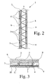
- Fig. 2 shows the finished part 1 in a schematic, not to scale cut.
- Fig. 3 shows a part of the finished part 1 in the production in a sectional, not to scale, schematic representation.
- the finished part 1 At least substantially plate-shaped natural stones 3, such as porphyry or Buntsandsteinplatten used.
- natural stones 3 such as porphyry or Buntsandsteinplatten used.
- artificial stone slabs or the like. can be used, so that the term "natural stones" is preferably interpreted accordingly wide.
- the natural stones 3 have a more or less smooth or even front side V and / or rear side R. However, natural stones 3 may also have a more or less rough or coarsely carved or otherwise structured surface, in particular front side V and / or rear side R, be used.
- the natural stones 3 preferably have a mean thickness of 2 to 8 cm, in particular of about 3 to 5 cm.
- the natural stones 3 are designed flat, so that the later covered with natural stones 3 surface is preferably as completely as possible covered with natural stones 3, so only as small or narrow joints 4 between the natural stones 3 are formed. If necessary, an optimal arrangement and selection of natural stones 3 can be controlled or supported by a corresponding computer program. If necessary, individual natural stones 3 can be cut or processed in any other way in order to achieve the required or desired plate sizes, shapes and / or contours.
- the joints 4 are grouted between the natural stones 3, in particular filled with a suitable grout 5 or shed according to a particularly preferred embodiment.
- the joints 4 are filled only at a height of substantially 0.5 to 3 cm, in particular substantially 1 to 2 cm, so that the joint mortar 5 is set back from the back R of the natural stones 3, the joints 4 so far only partially filled with grout 5. This allows engagement of the concrete of the adjoining concrete wall 2 in the joints 4, whereby a better toothing and thus connection between the natural stones 3 and the concrete wall 2 can be achieved.
- joints 4 are preferably not completely filled or grouted to the front V of the natural stones 3 with joint mortar 5 or concrete of the first concrete wall 2. This will be explained later.
- the natural stones 3 may be provided on the back with a bonding agent or adhesive. This is particularly useful for relatively smooth backs R of natural stones 3.
- the first concrete wall 2 is poured directly against the natural stones 3, in particular to the upwardly facing backs R of the preferably lying natural stones.
- the first concrete wall 2 is preferably poured with still moist or uncured grout 5 on the natural stones 3 in order to obtain a good connection between the concrete and the grout 5 and / or sufficient adaptability of the grout 5 to compensate for the casting process eventually occurring movements or displacements of natural stones 3 relative to each other to ensure.
- the first concrete wall 2, in the illustrated embodiment, preferably has an average thickness of 3 to 10 cm, in particular approximately 4 to 7 cm.
- the finished part 1 preferably has a second concrete wall 6, which is arranged in particular parallel and spaced from the first concrete wall 2, so that between the two concrete walls 2 and 6, a gap 7 is formed, as indicated in Fig. 2.
- the two concrete walls 2 and 6 are preferably connected by means of a cast-in connection element, such as a lattice girder 8. Accordingly, in the production of the first concrete wall 2, preferably already the lattice girder 8 and preferably a suitable reinforcement 9 is poured. After sufficient hardening or hardening of the first concrete wall 2, the natural stones 3 are connected to the first concrete wall 2. The first concrete wall 2 with the natural stones 3 and the cast-in lattice girder 8 is then reversed, so that then the second concrete wall 6 can be poured onto the lattice girder 8. Preferably, a suitable reinforcement 9 or the like is also poured into the second concrete wall 6.
- a suitable reinforcement 9 or the like is also poured into the second concrete wall 6.
- the second concrete wall 6 preferably has at least substantially the same thickness as the first concrete wall 2 or as the composite formed from the first concrete wall 2 and the natural stones 3.
- the distance between the two concrete walls 2 and 6 is preferably between 8 and 30 cm, in particular approximately between 10 and 20 cm, as proposed Prefabricated part 1. This allows the formation of very stable walls, especially of heavy duty walls.
- the proposed finished part 1 is formed at least substantially plate-shaped. This applies both with and without the optionally provided second concrete wall 6.
- the finished part 1 is provided in the representation example only on a flat side, namely the outside, the first concrete wall 2 with the natural stones 3.
- the natural stones 3 cover this flat side at least substantially completely.
- the finished part 1 can also be provided with the natural stones 3 on two sides.
- the additionally arranged on the back of the second concrete wall 2 natural stones 3 can be inserted or pressed, for example, immediately after the casting of the first concrete wall 2 in the still fresh concrete.
- the first concrete wall 2 can also be cast in two steps or layers, so that following the proposed procedure, the concrete wall 2 is cast successively against the two natural stone layers.
- the second concrete wall 6 can be provided with a natural stone layer corresponding to the first concrete wall 2, in which case the second concrete wall 6 is preferably poured directly against the second natural stone layer in accordance with the proposed method.
- the natural stones 3 are initially designed flat, preferably on a suitable support 10, as indicated in Fig. 3.
- the pad 10 is in particular a conventional steel formwork or the like for the production of concrete walls or similar.
- Fig. 3 shows a fragmentary, schematic section, wherein corresponding side walls of the formwork are not shown.
- the pad 10 is preferably at least substantially planar and / or in particular aligned horizontally. This allows a simple production, since the first concrete wall 2 can be poured directly without countershuttering on the flat-laid natural stones 3.
- the base 10 or a support 11 initially arranged thereon is designed such that its surface conforms to the front sides V of the natural stones 3 and / or at least pushes something into the joints 4.
- the pad 10 or - if present - the support 11 is designed to be correspondingly soft or elastically deformable, in particular made of a suitable plastic or rubber-like material.
- the support 11 it is also possible to use a suitable, in particular liquid or viscous material, which is first applied to the support 10 in a relatively small layer thickness. If the natural stones 3 are then placed, they press with their front sides V to the pad 10 in the material. Accordingly, the material completely covers the front sides V of the natural stones 3 and is pressed into the joints 4 up to a certain height depending on the filling quantity.
- the material is chosen or formed, in particular hydrophobic and / or viscous, that it does not mix with the natural stones 3 and not with the joint mortar 5 or the concrete formed the first concrete wall 2 or even mixes. Then follows the optional grouting and casting of the first concrete wall 2. After stripping or lifting the first concrete wall 2 with the natural stones 3, said material is removed again from the front. Preferably, said material is released from the front even again automatically due to gravity.
- Both by said soft or elastic training of the pad 10 or edition 11 as well as by the said material can be achieved that neither joint mortar 5 nor concrete of the first concrete wall 2 pollute the front V of natural stones 3 and / or the joints 4 not Completely be filled or grouted to the front sides V of the natural stones 3. Accordingly, a front panel is created without much cleaning effort, which corresponds to a natural stone wall produced in a conventional manner, at least substantially.
- the natural stones 3 are impregnated after production of the finished part 1 with a moss formation inhibiting or even preventing agent such as silica or the like.
- the finished finished part 1 is at least substantially aligned vertically with its concrete walls 2 and 6 for producing a natural stone wall.
- the finished part 1 can for example be placed on a prepared foundation or other foundation and / or embedded in a foundation or determined in any other way. Then we filled the gap 7 between the concrete walls 2 and 6, in particular concreted.
- a natural stone wall can be made on site or built in a very simple and fast way.
- the natural stone wall can also form a self-standing heavy-duty wall.
- the wall crown can be covered by suitable cover plates, which are laid, for example, in mortar. These cover plates can, if necessary, from the proposed finished parts 1 - then without second concrete wall 6 - are formed.
- the proposed finished part 1 is very simple and inexpensive to produce. Furthermore, the proposed finished part 1 is relatively easy, so that it is inexpensive and easy to transport to the desired site. From the proposed finished part 1 or more proposed precast 1 then a natural stone wall can be made very simple, as already explained, with several finished parts 1 can be firmly connected to each other by appropriate from a gap 7 in the next gap 7 probabilities.
- the prefabricated part 1, in particular formed without a second concrete wall may also have a foot, not shown, which is preferably formed in one piece with the first concrete wall 2 or integrally formed thereon is and extends preferably transversely to the main extension plane of the first concrete wall 2, in particular on both sides of the main extension plane.
Landscapes
- Chemical & Material Sciences (AREA)
- Engineering & Computer Science (AREA)
- Ceramic Engineering (AREA)
- Mechanical Engineering (AREA)
- Revetment (AREA)
Priority Applications (1)
| Application Number | Priority Date | Filing Date | Title |
|---|---|---|---|
| EP04029534A EP1671768A1 (fr) | 2004-12-14 | 2004-12-14 | Elément préfabriqué avec des pièrres naturelles et procédé de fabrication d'un tel élément |
Applications Claiming Priority (1)
| Application Number | Priority Date | Filing Date | Title |
|---|---|---|---|
| EP04029534A EP1671768A1 (fr) | 2004-12-14 | 2004-12-14 | Elément préfabriqué avec des pièrres naturelles et procédé de fabrication d'un tel élément |
Publications (1)
| Publication Number | Publication Date |
|---|---|
| EP1671768A1 true EP1671768A1 (fr) | 2006-06-21 |
Family
ID=34927761
Family Applications (1)
| Application Number | Title | Priority Date | Filing Date |
|---|---|---|---|
| EP04029534A Withdrawn EP1671768A1 (fr) | 2004-12-14 | 2004-12-14 | Elément préfabriqué avec des pièrres naturelles et procédé de fabrication d'un tel élément |
Country Status (1)
| Country | Link |
|---|---|
| EP (1) | EP1671768A1 (fr) |
Cited By (2)
| Publication number | Priority date | Publication date | Assignee | Title |
|---|---|---|---|---|
| ITPT20090017A1 (it) * | 2009-10-26 | 2011-04-27 | Ct Nord Srl | Foglie di pietra |
| WO2013174495A3 (fr) * | 2012-05-21 | 2014-03-06 | Progress Holding A.G. | Installation de fabrication d'une dalle de béton garnie d'éléments de revêtement |
Citations (8)
| Publication number | Priority date | Publication date | Assignee | Title |
|---|---|---|---|---|
| DE7419996U (de) | 1974-10-31 | Kauffmann W | Stützmauer-Element für Gartenanlagen | |
| DE2823748A1 (de) * | 1977-06-01 | 1978-12-14 | Ludovicus Houben | Verfahren fuer die herstellung vorgefertigter hohlmauern, gemaess demselben hergestellte hohlmauern und ausruestung fuer die durchfuehrung desselben |
| LU83159A1 (de) * | 1981-02-20 | 1981-06-05 | F Klimaytis | Verfahren zur herstellung von fertigbauwandplatten mit verblendung |
| FR2515567A1 (fr) * | 1981-10-30 | 1983-05-06 | Deshais Patrick | Procede de prefabrication d'elements d'ouvrages de maconnerie de moellons de pierre naturelle et produits en resultant |
| CH673114A5 (en) * | 1987-11-27 | 1990-02-15 | Vwd Vertrieb Wirtschaftlicher | Environment friendly stone surface treatment - by high pressure wet cleaning and impregnation |
| FR2734752A1 (fr) * | 1995-05-11 | 1996-12-06 | Brignoli Jean | Materiau composite granit, pierre ou marbre plus beton |
| DE10121591C1 (de) | 2001-05-03 | 2002-11-14 | Juergen Rothermel | Fertigteilbauelement |
| EP1270839A2 (fr) | 2001-06-19 | 2003-01-02 | Bertwin Schnubel | Elément de construction préfabriquée et transportable pour la réalisation de paroi et ou de plafond et procédé pour sa fabrication |
-
2004
- 2004-12-14 EP EP04029534A patent/EP1671768A1/fr not_active Withdrawn
Patent Citations (8)
| Publication number | Priority date | Publication date | Assignee | Title |
|---|---|---|---|---|
| DE7419996U (de) | 1974-10-31 | Kauffmann W | Stützmauer-Element für Gartenanlagen | |
| DE2823748A1 (de) * | 1977-06-01 | 1978-12-14 | Ludovicus Houben | Verfahren fuer die herstellung vorgefertigter hohlmauern, gemaess demselben hergestellte hohlmauern und ausruestung fuer die durchfuehrung desselben |
| LU83159A1 (de) * | 1981-02-20 | 1981-06-05 | F Klimaytis | Verfahren zur herstellung von fertigbauwandplatten mit verblendung |
| FR2515567A1 (fr) * | 1981-10-30 | 1983-05-06 | Deshais Patrick | Procede de prefabrication d'elements d'ouvrages de maconnerie de moellons de pierre naturelle et produits en resultant |
| CH673114A5 (en) * | 1987-11-27 | 1990-02-15 | Vwd Vertrieb Wirtschaftlicher | Environment friendly stone surface treatment - by high pressure wet cleaning and impregnation |
| FR2734752A1 (fr) * | 1995-05-11 | 1996-12-06 | Brignoli Jean | Materiau composite granit, pierre ou marbre plus beton |
| DE10121591C1 (de) | 2001-05-03 | 2002-11-14 | Juergen Rothermel | Fertigteilbauelement |
| EP1270839A2 (fr) | 2001-06-19 | 2003-01-02 | Bertwin Schnubel | Elément de construction préfabriquée et transportable pour la réalisation de paroi et ou de plafond et procédé pour sa fabrication |
Cited By (5)
| Publication number | Priority date | Publication date | Assignee | Title |
|---|---|---|---|---|
| ITPT20090017A1 (it) * | 2009-10-26 | 2011-04-27 | Ct Nord Srl | Foglie di pietra |
| WO2013174495A3 (fr) * | 2012-05-21 | 2014-03-06 | Progress Holding A.G. | Installation de fabrication d'une dalle de béton garnie d'éléments de revêtement |
| CN104395047A (zh) * | 2012-05-21 | 2015-03-04 | 进展控股股份公司 | 用于制造铺设有覆层元件的混凝土板的设备 |
| RU2598951C2 (ru) * | 2012-05-21 | 2016-10-10 | Прогресс Холдинг А.Г. | Установка для изготовления снабженной облицовочными элементами бетонной панели |
| CN104395047B (zh) * | 2012-05-21 | 2016-12-14 | 进展控股股份公司 | 用于制造铺设有覆层元件的混凝土板的设备 |
Similar Documents
| Publication | Publication Date | Title |
|---|---|---|
| DE60023894T2 (de) | Paneel und verfahren zur herstellung von betonwänden | |
| DE2354316C2 (de) | Gebäude aus Fertigbauteilen | |
| EP3085843B1 (fr) | Dispositif et procédé de couplage thermique de parties betonnées de bâtiment | |
| DE10018212B4 (de) | Verfahren zur Herstellung eines Beton-Deckenelements mit biegesteifen Beton- Trägerelementen, Deckenelement und Vorrichtung zur Durchführung des Verfahrens | |
| EP0757137A1 (fr) | Coffrage | |
| DE3790970C2 (de) | Fassadentafel | |
| EP1907642B1 (fr) | Procede de construction mur-plafond dans une execution en beton arme | |
| EP0051101B1 (fr) | Plaque en ciment et procédé et dispositif pour sa fabrication | |
| DE10310701A1 (de) | Verankerungssystem zur Übertragung und Schub-, Zug-, Druck-, Biegezug- und Torsionskräften in Beton und Betonfertigteilen | |
| AT391731B (de) | Deckenplatte und verfahren zu ihrer herstellung sowie anordnung zur durchfuehrung des verfahrens | |
| EP1605101A1 (fr) | Procédé et dispositif pour la fabrication d'un panneau multicouche en béton | |
| DE202004019390U1 (de) | Fertigteil | |
| EP1671768A1 (fr) | Elément préfabriqué avec des pièrres naturelles et procédé de fabrication d'un tel élément | |
| DE2714016A1 (de) | Zweischichtenplatte, insbesondere bodenplatte fuer spiel- und sportplaetze | |
| EP0170218A2 (fr) | Procédé pour la fabrication d'un élément de murage, élément de murage fabriqué selon le procédé et plaque de support pour l'élément | |
| DE19519314B4 (de) | Bodenplatte aus Kunststein | |
| DE19808812C2 (de) | Verfahren zur Herstellung einer festen Fahrbahn | |
| EP1431468A1 (fr) | Section du bâtiment avec des éléments de double parois et procédé de construction | |
| DE896860C (de) | In sich vorgespanntes Bewehrungselement aus Formsteinen | |
| EP0480295B1 (fr) | Ensemble pour la construction d'une maison d'habitation ou de vacances | |
| DE3025135A1 (de) | Verbundbauelement aus beton, insbesondere deckenelement, verfahren zu seiner herstellung und verwendung im bauwesen | |
| DE2636168A1 (de) | Verfahren und vorrichtung zum erstellen von bauwerken | |
| AT517855B1 (de) | Bausatz für einen Brüstungsaufbau | |
| DE2264362A1 (de) | Verlorene schalungsplatte | |
| DE10121864B4 (de) | Drempelwandvorrichtung |
Legal Events
| Date | Code | Title | Description |
|---|---|---|---|
| PUAI | Public reference made under article 153(3) epc to a published international application that has entered the european phase |
Free format text: ORIGINAL CODE: 0009012 |
|
| AK | Designated contracting states |
Kind code of ref document: A1 Designated state(s): AT BE BG CH CY CZ DE DK EE ES FI FR GB GR HU IE IS IT LI LT LU MC NL PL PT RO SE SI SK TR |
|
| AX | Request for extension of the european patent |
Extension state: AL BA HR LV MK YU |
|
| RAP1 | Party data changed (applicant data changed or rights of an application transferred) |
Owner name: ELSKES FERTIGTEILE GMBH & CO. KG |
|
| AKX | Designation fees paid | ||
| STAA | Information on the status of an ep patent application or granted ep patent |
Free format text: STATUS: THE APPLICATION IS DEEMED TO BE WITHDRAWN |
|
| 18D | Application deemed to be withdrawn |
Effective date: 20061222 |
|
| REG | Reference to a national code |
Ref country code: DE Ref legal event code: 8566 |