EP1666788A2 - Verfahren zur Auslegung einer Entladungslampe - Google Patents
Verfahren zur Auslegung einer Entladungslampe Download PDFInfo
- Publication number
- EP1666788A2 EP1666788A2 EP05012057A EP05012057A EP1666788A2 EP 1666788 A2 EP1666788 A2 EP 1666788A2 EP 05012057 A EP05012057 A EP 05012057A EP 05012057 A EP05012057 A EP 05012057A EP 1666788 A2 EP1666788 A2 EP 1666788A2
- Authority
- EP
- European Patent Office
- Prior art keywords
- reflector
- light
- burner
- lamp
- collecting system
- Prior art date
- Legal status (The legal status is an assumption and is not a legal conclusion. Google has not performed a legal analysis and makes no representation as to the accuracy of the status listed.)
- Granted
Links
- 238000000034 method Methods 0.000 title claims description 15
- 230000003287 optical effect Effects 0.000 claims description 8
- 101000912561 Bos taurus Fibrinogen gamma-B chain Proteins 0.000 abstract 1
- 238000009434 installation Methods 0.000 description 4
- 230000006978 adaptation Effects 0.000 description 3
- 230000005855 radiation Effects 0.000 description 3
- 238000010521 absorption reaction Methods 0.000 description 2
- 238000005516 engineering process Methods 0.000 description 2
- 230000002093 peripheral effect Effects 0.000 description 2
- 230000008646 thermal stress Effects 0.000 description 2
- 230000004323 axial length Effects 0.000 description 1
- 239000000919 ceramic Substances 0.000 description 1
- 238000001816 cooling Methods 0.000 description 1
- 230000001419 dependent effect Effects 0.000 description 1
- 238000010586 diagram Methods 0.000 description 1
- 230000003203 everyday effect Effects 0.000 description 1
- 239000011521 glass Substances 0.000 description 1
- 239000002241 glass-ceramic Substances 0.000 description 1
- 238000010438 heat treatment Methods 0.000 description 1
- 238000003384 imaging method Methods 0.000 description 1
- 239000000463 material Substances 0.000 description 1
- 238000005457 optimization Methods 0.000 description 1
- XOFYZVNMUHMLCC-ZPOLXVRWSA-N prednisone Chemical compound O=C1C=C[C@]2(C)[C@H]3C(=O)C[C@](C)([C@@](CC4)(O)C(=O)CO)[C@@H]4[C@@H]3CCC2=C1 XOFYZVNMUHMLCC-ZPOLXVRWSA-N 0.000 description 1
- WFKWXMTUELFFGS-UHFFFAOYSA-N tungsten Chemical compound [W] WFKWXMTUELFFGS-UHFFFAOYSA-N 0.000 description 1
- 229910052721 tungsten Inorganic materials 0.000 description 1
- 239000010937 tungsten Substances 0.000 description 1
Images


Classifications
-
- H—ELECTRICITY
- H04—ELECTRIC COMMUNICATION TECHNIQUE
- H04N—PICTORIAL COMMUNICATION, e.g. TELEVISION
- H04N9/00—Details of colour television systems
- H04N9/12—Picture reproducers
- H04N9/31—Projection devices for colour picture display, e.g. using electronic spatial light modulators [ESLM]
- H04N9/3141—Constructional details thereof
- H04N9/315—Modulator illumination systems
-
- F—MECHANICAL ENGINEERING; LIGHTING; HEATING; WEAPONS; BLASTING
- F21—LIGHTING
- F21V—FUNCTIONAL FEATURES OR DETAILS OF LIGHTING DEVICES OR SYSTEMS THEREOF; STRUCTURAL COMBINATIONS OF LIGHTING DEVICES WITH OTHER ARTICLES, NOT OTHERWISE PROVIDED FOR
- F21V7/00—Reflectors for light sources
- F21V7/04—Optical design
Definitions
- the invention relates to a method for designing a discharge lamp according to the preamble of claim 1 and to a lamp designed according to such a method and to a reflector designed according to such a method.
- the optical system (light engine) of digital projectors usually has a microdisplay panel, which in principle represents a chip on the surface of which controllable pixels are arranged.
- the optical system of the projector illuminates the panel and projects the resulting image onto the wall using the projection lens.
- three main types of microdisplays are distinguished: DMD, LCD, LCoS.
- the miniaturization of the projectors depends, among other things, on the size of these microdisplay panels and also on the light sources used.
- the basic structure of a projector with LCD panel is For example, in the US 5,902,033, while referring to the function of the DMD panels on the relevant patent applications of the company Texas Instruments, which are directed to the DLP method (Digital Light Processing ®).
- the light source used is predominantly high-pressure discharge lamps, as described for example under www.osram.com under video and projection lamps (VIP lamps).
- These high-pressure discharge lamps have a burner which is inserted in a glass reflector.
- these burners have an approximately centrally arranged discharge chamber, which merges into two burner shafts arranged diametrically opposite one another. Due to the comparatively large axial length of these burners, a part of the emitted radiation is reflected onto the end portion of the shaft, so that it is exposed to a strong thermal load.
- EP 1 220 294 A1 it is proposed to provide the end section of the shaft with a reflection layer which acts as a heat protection layer and reflects the radiation that occurs, so that additional heating of the burner in this area can be avoided.
- a supply of cooling air can take place, but the fans required for this increase both the installation space of the projector and its noise emissions.
- the design of the reflector takes place as a function of a few parameters, such as the etendue (light conductance) and the acceptance angle of the light-collecting system and the length of a discharge arc of an inserted discharge lamp. These parameters then allow the numerical eccentricity, i. h., determine the shape of the elliptical reflector, whereby an eccentricity calculated on the basis of the acceptance angle is corrected with an adaptation value which depends on the etendue and the arc length. That is, with this adjustment value, the reflector is adapted to the light-collecting system.
- the shape of the ellipse is thus determined as a function of these parameters, wherein two of the parameters (etendue and acceptance angle) are predetermined by the optical system, while the third parameter (arc length) is predetermined by the lamp used. Regardless of the size of the reflector then the maximum efficiency of the light-collecting system is guaranteed.
- the invention thus makes it possible, in an extremely simple manner, to adapt the geometry of an elliptical reflector optimally to the light-collecting system, for example a projector, as a function of a few parameters.
- the two ellipse axes can be selected at the predetermined eccentricity so that the thermal load of the reflector or the lamp described above is minimal.
- the larger focal length in which the light beams emitted by the burner are bundled by means of the elliptical reflector can be determined as a function of the length and diameter of a burner shaft and of the previously calculated eccentricity. With knowledge of this focal length, the two ellipse axes can then be calculated by simple geometrical considerations.
- the length of the lamp can be further reduced by allowing the torch stem to project slightly out of the aperture hole.
- the angle range beyond which the burner protrudes from the aperture hole is included in the calculation of the larger focal length.
- the space required for the installation of the reflector space is minimal when it is provided with flats, two of which are arranged at a parallel distance from each other, preferably wherein the distance between two flats is less than the distance of the other two flats.
- the burner is preferably designed as a high-pressure discharge lamp.
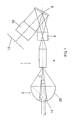
- FIG. 1 shows the basic structure of a DLP (Digital Light Processing) projector for video projection.
- the optical system of the projector 1 consists essentially of a HID lamp (high-intensity discharge lamp) 2, an integrator 4, a relay optics 6, a DMD chip 8 and the lens 10, on the image on a screen 12 is projected. Not shown is the color wheel used in the DLP technique, which is usually arranged between the integrator 4 and the lamp 2.
- the components HID lamp 2, integrator 4, relay optics 6, DMD chip 8 and lens 10 are also referred to as light engine.
- FIG. 2 shows an enlarged view of the HID lamp 2 of Figure 1. Accordingly, this has a burner 14, whose piston has a discharge vessel 16 approximately centrally, to connect two axially projecting burner shafts 18, 20.
- a burner 14 whose piston has a discharge vessel 16 approximately centrally, to connect two axially projecting burner shafts 18, 20.
- two tungsten electrodes 22, 24 are arranged, which are arranged with a predetermined distance from one another, which determines the length g (not shown) of a discharge arc.
- the burner 14 is inserted into an elliptical, substantially rotationally symmetrical reflector 26, which is provided with a reflection layer.
- the discharge vessel 16 with the two electrodes 22, 24 is arranged so that the resulting discharge arc lies in a focal point F 1 of the reflector 26.
- the light generated in the discharge vessel 16 by the discharge arc is imaged by the reflector 26 on the focus F 2 , which lies in the input aperture of the integrator 4. Since the discharge arc does not represent a punctiform light source, this image does not take place-as shown in idealized form in FIG. 2-punctiform exactly in focus F 2 .
- the light emitted by the HID lamp 2 is equalized by multiple reflection in the integrator 4 and then displayed on the output side via the relay optics 6 on the DMD chip 8. Over this the actual picture is produced.
- 600,000 pivoting micromirrors which act as a light valve, are located on the DMD chip 8. Depending on the mirror position, an image pixel can be created or remain dark.
- the light reflected by the DMD chip 8 receives the corresponding color information from the color wheel arranged in front of it. Grayscale and color nuances are reflected by a correspondingly longer or shorter reflection time.
- the image delivered by the DMD chip 8 is finally imaged on the screen 12 via the objective 10.
- the light-collecting system of the projector 1 with the integrator 4, the relay optics 6 and the DMD chip 8 is usually given, so that accordingly the etendue (area and acceptance angle) of the DMD chip 8 are given as constants.
- the mirrors of the DMD chip 8 of a 0.7 "DMD chip 8 can usually be deflected by 12 ° so that the acceptance angle ⁇ of the DMD chip is corresponding to 12 °. such that the acceptance angle ⁇ 'of the light collecting system is approximately between 20 ° and 40 °. An optimization can then take place in an existing projection system usually only by suitable design of the HID lamp 2.
- a reflector 26 is to be designed, which is built as compact as possible and further minimizes the thermal stress on the components of the HID lamp 2.
- thermal problems may occur, in particular the distance of the burner 14 to the reflector 26 is critical because too small a distance to a close thermal contact between the burner 14 and reflector 26th can lead. So far, a thermal load was avoided by, for example, high-quality glass ceramic reflectors were used or the burner were cemented by means of a cementing in a ceramic part of the reflector.
- Figure 3 shows an ellipsoid, after which the reflector 26 is made.
- This ellipsoid is characterized inter alia by the focal point F 1 and the focus F 2 , wherein the distance of the focal point F 1 from the vertex 28 defines the focal length f 1 , while the distance of the focus F 2 from the vertex 28 corresponds to the focal length f 2 .
- the two ellipse half-axes a (longer semiaxis) and b (shorter semiaxis) are shown in FIG.
- a light beam emanating from the focal point F 1 is reflected by the ellipsoid towards the focus F 2 - in FIG. 3, this light beam is incident, for example, at the angle ⁇ 'towards the focus F 2 .
- the burner 14 is arranged in the optical axis 30 of the reflector 26 such that the burner shaft 20, in particular its end face 32, is arranged completely within the aperture hole 35, which is characterized by the aperture cone 34. This limits that area of the burner 14 in which no imaging takes place. If now the end face 32 is inserted into this aperture cone 34, then the radiation reflected by the reflector 26 does not impinge on the burner shaft 20, so that it is not additionally heated by absorption of radiant energy.
- the end face 32 is not exactly in the aperture cone 34 but stands with its outer peripheral portions 36 (see enlarged view of Figure 4) beyond the aperture cone 34 addition.
- the reference numeral 32 ' is in the figures 2 and 4 that position of the end face 32 marked, in which this would lie completely in the aperture cone 34 - to this position reach, then an axially shorter built burner 14 should be used.
- this angular range is characterized by the angle ⁇ in Figure 4 and should be less than 2 °, preferably less than 1 °.
- the end face (as shown at 32 ') is completely inserted into the aperture cone 34.
- This focal length ratio m can be determined as a function of the numerical eccentricity e 0 calculated at the outset.
- the thermal load of the burner 14 can be lowered further, if the focal length f 1 , ie, the center distance of the discharge vessel 16 from the vertex 28 of the ellipsoid is chosen larger than 8 mm, so that the burner and the reflector are reliably thermally decoupled.
- the reduction of the numerical eccentricity caused by the adaptation factor ⁇ e not only leads to an optimum efficiency of the system, but also to an increase of the focal length ratio of m and thus for a given f value f 2 to a larger f 1 and thus to a greater distance between the discharge vessel 16 and the apex 28 of the reflector.
- FIG. 5 shows a further possibility of minimizing the installation space required for the HID lamp 2.
- the reflector 26 with flats 38, 40 and two above and below the plane in Figure 5 shown flats 42, 44 are provided, which are indicated by dashed lines in Figure 5. These flattenings are created by "cutting away” the indicated hatched in Figure 5 areas. As shown in FIG. 5, at the flats 42, 44, more material has been removed from the original circular reflector 26 than is required for the flats 38, 40. D. h., The reflector 26 has perpendicular to the plane in Figure 5 has a smaller width than in the Plane. The flats are a compromise between small size and high efficiency.
- a HID lamp 2 was used.
- other discharge lamps with regard to the design of the dimensions a, b, in principle, incandescent lamps are used.
- incandescent lamps are used.
- DMD chips 8 other types, for example the types mentioned in the introduction to the description, may also be used.
- the invention relates to a method for designing a discharge lamp for use with a light-collecting system, in particular a projector for data or video projection. Furthermore, a lamp designed according to such a method and a reflector provided therefor are disclosed.
Landscapes
- Engineering & Computer Science (AREA)
- General Engineering & Computer Science (AREA)
- Multimedia (AREA)
- Signal Processing (AREA)
- Projection Apparatus (AREA)
- Non-Portable Lighting Devices Or Systems Thereof (AREA)
- Fastening Of Light Sources Or Lamp Holders (AREA)
- Discharge Lamps And Accessories Thereof (AREA)
- Discharge Lamp (AREA)
Abstract
Description
- Die Erfindung betrifft ein Verfahren zur Auslegung einer Entladungslampe nach dem Oberbegriff des Anspruchs 1 sowie eine nach einem derartigen Verfahren ausgelegte Lampe und einen nach einem derartigen Verfahren ausgelegten Reflektor.
- Der Markt für Digitalprojektoren zur Daten- oder Videoprojektion wächst seit Erfindung der DLP-Technologie weltweit stark an. Diese zunehmende Verbreitung ist unter anderem auch damit begründet, dass die Projektoren aufgrund der eingesetzten Technologien immer preisgünstiger herstellbar sind und in ihren Abmessungen so kompakt ausgeführt werden, dass sie einen mobilen Einsatz im Büroalltag ermöglichen.
- Das optische System (light engine) von Digitalprojektoren weist üblicherweise ein Mikrodisplay-Panel auf, das im Prinzip einen Chip darstellt, auf dessen Oberfläche ansteuerbare Pixel angeordnet sind. Durch das optische System des Projektors wird das Panel beleuchtet und das entstehende Bild mittels des Projektionsobjektivs an die Wand projeziert. Prinzipiell werden drei Haupttypen von Mikrodisplays unterschieden: DMD, LCD, LCoS. Die Miniaturisierung der Projektoren hängt unter anderem von der Größe dieser Mikrodisplay-Panels und auch von den eingesetzten Lichtquellen ab. Der Grundaufbau eines Projektors mit LCD-Panel ist beispielsweise in der US 5,902,033 beschrieben, während hinsichtlich der Funktion der DMD-Panels auf die einschlägigen Patentanmeldungen der Firma Texas Instruments verwiesen wird, die auf das DLP-Verfahren (Digital Light Processing ®) gerichtet sind.
- Bei den vorbeschriebenen digitalen Projektionssystemen werden als Lichtquelle überwiegend Hochdruckentladungslampen eingesetzt, wie sie beispielsweise unter www.osram.com unter Video- und Projektionslampen (VIP-Lampen) beschrieben sind. Diese Hochdruckentladungslampen haben einen Brenner, der in einen Glasreflektor eingesetzt ist. Bei der Auslegung derartiger Hochdruckentladungslampen muss beachtet werden, dass bei den auftretenden sehr hohen Temperaturen weder der Reflektor noch der Brenner thermisch geschädigt werden. Diese Brenner haben in der Regel eine etwa mittig angeordnete Entladungskammer, die in zwei diametral zueinander angeordnete Brennerschäfte übergeht. Aufgrund der vergleichsweise großen Axiallänge dieser Brenner wird ein Teil der abgegebenen Strahlung auf den Endabschnitt des Schafts reflektiert, so dass dieser einer starken thermischen Belastung ausgesetzt ist. In der EP 1 220 294 A1 wird vorgeschlagen, den Endabschnitt des Schafts mit einer Reflexionsschicht zu versehen, die als Wärmeschutzschicht wirkt und die auftretende Strahlung reflektiert, so dass eine zusätzliche Erwärmung des Brenners in diesem Bereich vermieden werden kann. Alternativ oder zusätzlich kann eine Zufuhr von Kühlluft erfolgen, die dafür erforderlichen Lüfter vergrößern jedoch sowohl den Bauraum des Projektors als auch dessen Lärmemissionen.
- Es ist Aufgabe der vorliegenden Erfindung, ein Verfahren zur Auslegung einer Entladungslampe, eine nach einem derartigen Verfahren ausgelegte Lampe, insbesondere eine Entladungslampe und einen dafür geeigneten Reflektor zu schaffen, die einen minimalen Bauraum, eine hohe optische Effizienzund eine geringe thermische Beslastung aufweisen.
- Diese Aufgabe wird hinsichtlich des Verfahrens durch die Merkmalskombination des Anspruchs 1, hinsichtlich der Lampe, insbesondere der Entladungslampe durch die Merkmalskombination des Anspruchs 5 und hinsichtlich des Reflektors durch die Merkmalskombination des Anspruchs 9 gelöst. Besondere vorteilhafte Ausgestaltungen finden sich in den abhängigen Ansprüchen.
- Erfindungsgemäß erfolgt die Auslegung des Reflektors in Abhängigkeit von einigen wenigen Parametern, wie von der Etendue (Lichtleitwert) und vom Akzeptanzwinkel des lichtsammelnden Systems und von der Länge eines Entladungsbogens einer eingesetzten Entladungslampe. Mit diesen Parametern lässt sich dann die numerische Exzentrizität, d. h., die Form des elliptischen Reflektors bestimmen, wobei eine in Abhängigkeit vom Akzeptanzwinkel berechnete Exzentrizität mit einem Anpassungswert korrigiert wird, der von der Etendue und der Bogenlänge abhängt. D. h., mit diesem Anpassungswert erfolgt eine Anpassung des Reflektors an das lichtsammelnde System.
- Erfindungsgemäß wird somit die Form der Ellipse in Abhängigkeit von diesen Parametern ermittelt, wobei zwei der Parameter (Etendue und Akzeptanzwinkel) durch das optische System vorgegeben sind, während der dritte Parameter (Bogenlänge) durch die verwendete Lampe vorgegeben ist. Unabhängig von der Größe des Reflektors ist dann die maximale Effizienz des lichtsammelnden Systems gewährleistet.
- Die Erfindung ermöglicht es somit, auf äußerst einfache Weise die Geometrie eines elliptischen Reflektors in Abhängigkeit von wenigen Parametern in optimaler Weise an das lichtsammelnde System, beispielsweise eines Projektors anzupassen.
- Um den Bauraum des Systems weiter zu minimieren, können erfindungsgemäß die beiden Ellipsenachsen bei der vorgegebenen Exzentrizität so ausgewählt werden, dass die eingangs beschriebene thermische Belastung des Reflektors oder der Lampe minimal ist.
- Bei Entladungslampen für Projektionssysteme ist der Entladungsbogen im Brennpunkt F1 (kleinere Brennweite) des elliptischen Reflektors angeordnet. Diese Brennweite wird erfindungsgemäß ≥ 8 mm gewählt - es zeigte sich, dass dieses Maß ein optimaler Kompromiss zwischen einer kompakten Bauweise und einer minimalen thermischen Belastung des Brenners und des Reflektors darstellt. Die Größe des Reflektors wird so gewählt, dass der Brenner sich entweder vollständig oder nahezu im Aperturloch befindet. Unter einem derartigen Aperturloch wird ein mittiger Bereich verstanden, in den der Reflektor aufgrund der typischen Strahlstärkeverteilung des Brenners nicht abstrahlt. In Abhängigkeit von dieser Bedingung (Brennerende liegt innerhalb des Aperturlochs) lässt sich die größere Brennweite, in der die vom Brenner abgestrahlten Lichtstrahlen mittels des elliptischen Reflektors gebündelt werden, in Abhängigkeit von der Länge und dem Durchmesser eines Brennerschaftes sowie von der zuvor berechneten Exzentrizität ermitteln. In Kenntnis dieser Brennweite können dann durch einfache geometrische Betrachtungen die beiden Ellipsenachsen berechnet werden.
- Die Baulänge der Lampe lässt sich weiter verkürzen, wenn zugelassen wird, dass der Brennerschaft etwas aus dem Aperturloch hervorsteht. In diesem Fall geht in die Berechnung der größeren Brennweite zusätzlich zu den vorbeschriebenen Parametern dann noch der Winkelbereich ein, um den der Brenner aus dem Aperturloch heraussteht.
- Der für den Einbau des Reflektors erforderliche Bauraum ist minimal, wenn dieser mit Abflachungen versehen wird, von denen jeweils zwei im Parallelabstand zueinander angeordnet sind, wobei vorzugsweise der Abstand zweier Abflachungen geringer ist als der Abstand der beiden anderen Abflachungen.
- Der Brenner wird vorzugsweise als Hochdruckentladungslampe ausgeführt.
- Im folgenden wird die Erfindung anhand von Ausführungsbeispielen unter Bezugnahme auf Zeichnungen näher erläutert. Es zeigen:
- Figur 1
- eine Schemadarstellung eines Projektors mit einer Hochdruckentladungslampe und einem optischen System des Projektors;
- Figur 2
- eine Prinzipdarstellung zur Erläuterung der Geometrie eines elliptischen Reflektors der Hochdruckentladungslampe aus Figur 1;
- Figur 3
- eine vergrößerte Darstellung der Hochdruckentladungslampe aus Figur 1;
- Figur 4
- eine Variante der Hochdruckentladungslampe gemäß Figur 3;
- Figur 5
- ein weiteres Ausführungsbeispiel einer Hochdruckentladungslampe mit abgeflachtem Reflektor und
- Figur 6
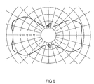
- eine Strahlstärkeverteilung einer Hochdruckentladungslampe.
- Figur 1 zeigt den Grundaufbau eines DLP (Digital Light Processing)-Projektors zur Videoprojektion. Das optische System des Projektors 1 besteht im Wesentlichen aus einer HID-Lampe (High-Intensity-Discharge-Lampe) 2, einem Integrator 4, einer Relay-Optik 6, einem DMD-Chip 8 sowie dem Objektiv 10, über das die Abbildung auf einen Bildschirm 12 projeziert wird. Nicht dargestellt ist das bei der DLP-Technik verwendete Farbrad, das meist zwischen dem Integrator 4 und der Lampe 2 angeordnet ist. Die Bauelemente HID-Lampe 2, Integrator 4, Relay-Optik 6, DMD-Chip 8 sowie Objektiv 10 werden auch als light engine bezeichnet.
- Figur 2 zeigt eine vergrößerte Darstellung der HID-Lampe 2 aus Figur 1. Demgemäß hat diese einen Brenner 14, dessen Kolben etwa mittig ein Entladungsgefäß 16 hat, an sich zwei axial vorspringende Brennerschäfte 18, 20 anschliessen. Im Entladungsgefäß 16 sind zwei Wolfram-Elektroden 22, 24 (schematisch dargestellt) angeordnet, die mit einem vorbestimmten Abstand zueinander angeordnet sind, der die Länge g (nicht dargestellt) eines Entladungsbogens bestimmt.
- Der Aufbau derartiger HID-Lampen ist bekannt, diese werden beispielsweise unter www.osram.de unter dem Namen VIP-Lampen beschrieben, so dass weitere Erläuterungen entbehrlich sind.
- Der Brenner 14 ist in einen elliptischen, im Wesentlichen rotationssymetrischen Reflektor 26 eingesetzt, der mit einer Reflektionsschicht versehen ist. Das Entladungsgefäß 16 mit den beiden Elektroden 22, 24 ist so angeordnet, dass der entstehende Entladungsbogen in einem Brennpunkt F1 des Reflektors 26 liegt. Das im Entladungsgefäß 16 durch den Entladungsbogen erzeugte Licht wird durch den Reflektor 26 auf den Fokus F2 abgebildet, der in der Eingangsapertur des Integrators 4 liegt. Da der Entladungsbogen keine punktförmige Lichtquelle darstellt erfolgt diese Abbildung nicht - wie in Figur 2 idealisiert dargestellt - punktförmig exakt im Fokus F2.
- Das von der HID-Lampe 2 abgestrahlte Licht wird durch Mehrfachreflektion im Integrator 4 vergleichmäßigt und dann austrittsseitig über die Relay-Optik 6 auf den DMD-Chip 8 abgebildet. Über diesen wird das eigentliche Bild erzeugt. Auf dem DMD-Chip 8 befinden sich je nach Ausführung beispielsweise 600.000 schwenkbare Mikrospiegel, die als Lichtventil wirken. Je nach Spiegeistellung kann dabei ein Bildpixel erzeugt werden oder dunkel bleiben. Das von dem DMD-Chip 8 reflektierte Licht bekommt von dem davor angeordneten Farbrad die entsprechende Farbinformation. Graustufen und Farbnuancen werden durch eine entsprechend längere oder kürzere Reflektionszeit wiedergegeben. Das vom DMD-Chip 8 abgegebene Bild wird schließlich über das Objektiv 10 auf die Leinwand 12 abgebildet.
- Bei der Auslegung der Projektoren 1 ist man bemüht, diese möglichst kompakt und mit hoher Effizienz auszubilden, so dass eine brilliante Projektion mit großer Helligkeit und gutem Kontrast ermöglicht ist. Dabei ist das lichtsammelnde System des Projektors 1 mit dem Integrator 4, der Relay-Optik 6 und dem DMD-Chip 8 in der Regel vorgegeben, so dass entsprechend auch die Etendue (Fläche und Akzeptanzwinkel) des DMD-Chip 8 als Konstanten vorgegeben sind.
- Die Spiegel des DMD-Chips 8 eines 0,7"-DMD-Chips 8 lassen sich üblicherweise um 12° auslenken, so dass der Akzeptanzwinkel γ des DMD-Chips entsprechend 12° beträgt. Durch die Relay-Optik 6 wird dieser Akzeptanzwinkel aufgeweitet, so dass der Akzeptanzwinkel γ' des lichtsammelnden Systems etwa zwischen 20° und 40° beträgt. Eine Optimierung kann dann in einem vorhandenen Projektionssystem in der Regel nur durch geeignete Auslegung der HID-Lampe 2 erfolgen.
- Es sei nun angenommen, dass bei gegebenem Brenner 14 mit einer bestimmten Länge g des Entladungsbogens und einer Länge L (Figur 2) des halben Brenners 14 (Abstand Mittelpunkt des Entladungsgefässes 16 bis Stirnfläche des Brennerschafts 20) und einem vorhandenen lichtsammelnden System mit der Etendue E und dem Akzeptanzwinkel γ' ein Reflektor 26 ausgelegt werden soll, der möglichst kompakt gebaut ist und des Weiteren die thermische Belastung der Bauelemente der HID-Lampe 2 minimiert.
- In einem ersten Auslegungsschritt wird zunächst die die Geometrie des Reflektors 26 im Wesentlichen charakterisierende Exzentriezität ea bestimmt. Diese berechnet sich nach:

mit γ': Akzeptanzwinkel - In einem weiteren Schritt wird ein Anpassungsfaktor für die Exzentrizität berechnet, der im Wesentlichen von den vorgenannten Parametern des Projektors 1 abhängt. Dieser Anpassungsfaktor Δe berechnet sich nach:

- mit g: Länge des Entladungsbogens;
- E: Etendue
- γ': Akzeptanzwinkel.
- Die numerische Exzentrizität e0 berechnet sich dann aus der Differenz zwischen der Exzentrizität ea und dem Anpassungsfaktor Δe:

- Bei einem 0,7"-DMD-Chip 6 mit einem Spiegelkippwinkel von 12° und einer Etendue von E = 20 mm2sr ergeben sich dann bei einer bestimmten Relay-Optik 6 die in Tabelle 1 dargestellten numerischen Exzentrizitätswerte e0 bei einem von der Relay-Optik 6 bestimmten Akzeptanzwinkel γ'.
Tabelle 1 γ' ea eo 23° 0.85 0.81 29° 0.81 0.77 34° 0.77 0.72 - Mit den vorbeschriebenen Auslegungsregeln ist somit die Grundform des elliptischen Reflektors 26 vorgegeben. Zur Minimierung des Reflektors 26 müssen einige thermische Auslegungskriterien berücksichtigt werden.
- Wie eingangs erläutert, können beim Betrieb eines hochwattigen Brenners in einem sehr kleinen elliptischen Reflektor thermische Probleme auftreten, wobei im Besonderen der Abstand des Brenners 14 zum Reflektor 26 kritisch ist, da ein zu kleiner Abstand zu einem engen thermischen Kontakt zwischen Brenner 14 und Reflektor 26 führen kann. Bisher wurde eine thermische Belastung dadurch vermieden, dass beispielsweise hochwertige Reflektoren aus Glaskeramik verwendet wurden oder die Brenner mittels einer Kittung in ein Keramikteil des Reflektors eingekittet wurden.
- Ein weiteres thermisches Problem besteht darin, dass der Brennerschaft 20 so lang ist, dass er in den abgestrahlten Lichtkegel hineinragt und durch Absorption des Lichtes erwärmt wird. Zur Beseitigung dieses Problems wurde in der eingangs genannten EP 1 220 294 A1 angeregt, den Endabschnitt des Brennerschaftes 20 mit einer Reflektionsschicht zu versehen. Die Erfindung wendet sich von dieser vergleichsweise aufwendigen Lösung ab und vermeidet die thermische Belastung durch geeignete Auslegung des Reflektors 26. Dies wird anhand der schematischen Darstellungen in den Figuren 2 bis 5 erläutert.
- Figur 3 zeigt ein Ellipsoid, nach dem der Reflektor 26 gefertigt ist. Dieses Ellipsoid ist unter anderem durch den Brennpunkt F1 und den Fokus F2 gekennzeichnet, wobei der Abstand des Brennpunkts F1 vom Scheitel 28 die Brennweite f1 definiert, während der Abstand des Fokus F2 vom Scheitel 28 der Brennweite f2 entspricht. In Figur 3 sind des Weiteren die beiden Ellipsenhalbachsen a (längere Halbachse) und b (kürzere Halbachse) eingezeichnet. Ein vom Brennpunkt F1 ausgehender Lichtstrahl wird durch den Ellipsoid zum Fokus F2 hin reflektiert - in Figur 3 fällt dieser Lichtstrahl beispielhaft mit dem Winkel γ' zum Fokus F2 hin ein.
- Erfindungsgemäß wird der Brenner 14 derart in der optischen Achse 30 des Reflektors 26 angeordnet, dass der Brennerschaft 20, insbesondere dessen Stirnfläche 32 vollständig innerhalb des Aperturlochs 35 angeordnet ist, das durch den Aperturkegel 34 gekennzeichnet ist. Dieser begrenzt denjenigen Bereich des Brenners 14 in dem keine Abbildung erfolgt. Legt man nun die Stirnfläche 32 in diesen Aperturkegel 34 hinein, so trifft die vom Reflektor 26 reflektierte Strahlung nicht auf den Brennerschaft 20 auf, so dass dieser auch nicht zusätzlich durch Absorption von Strahlungsenergie erwärmt wird.
- Bei dem in Figur 2 dargestellten Ausführungsbeispiel liegt die Stirnfläche 32 nicht exakt im Aperturkegel 34 sondern steht mit ihren Aussenumfangsabschnitten 36 (siehe vergrößerte Darstellung gemäß Figur 4) über den Aperturkegel 34 hinaus. Mit dem Bezugszeichen 32' ist in den Figuren 2 und 4 diejenige Position der Stirnfläche 32 gekennzeichnet, bei der diese vollständig im Aperturkegel 34 liegen würde - um diese Position zu erreichen, müsste dann ein axial kürzer gebauter Brenner 14 verwendet werden.
- Erfindungsgemäß kann jedoch ein geringes Herausragen der Umfangsabschnitte 36 - wie in Figur 4 dargestellt - akzeptiert werden, wobei dieser Winkelbereich durch den Winkel ζ in Figur 4 gekennzeichnet ist und weniger als 2°, vorzugsweise weniger als 1° betragen sollte.
- Für den Fall, in dem die thermische Belastung des Brennerschafts 20 minimal sein soll, wird die Stirnfläche (wie mit 32' dargestellt) vollständig in den Aperturkegel 34 eingebracht. Bei gegebener Länge L und Durchmesser d des Brennerschafts 20 berechnet sich die Brennweite f2 dann nach
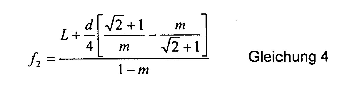

- Dieses Brennweitenverhältnis m kann in Abhängigkeit von der eingangs berechneten numerischen Exzentrizität e0 ermittelt werden.
- Aus dieser Brennweite f2 errechnet sich dann die größere Ellipsenhalbachse a nach


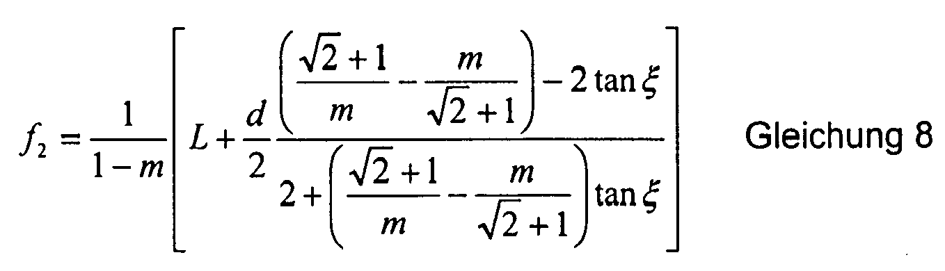
- In dem Fall, in dem ein geringes Herausragen des Brennerschaftes 20 aus dem Aperturkegel 34 und somit eine geringfügige thermische Belastung des Brenners 14 zugelassen wird, berechnet sich die Brennweite f2 nach der Gleichung 8

- Aus den Gleichungen 6, 7 können dann wieder die beiden Halbachsen a, b der Ellipse in Abhängigkeit von der Brennweite f2 und der numerischen Exzentrizität e0 berechnet werden.
- Die thermische Belastung des Brenners 14 lässt sich weiter absenken, wenn die Brennweite f1, d. h., der Mittelabstand des Entladungsgefäßes 16 vom Scheitel 28 des Ellipsoids größer als 8 mm gewählt wird, so dass der Brenner und der Reflektor zuverlässig thermisch entkoppelt sind.
- Wendet man die vorbeschriebenen Auslegungskriterien auf einen Projektor mit einem 0.7"-DMD-Chip 8 mit 12° Kippwinkel (10 % overfill) an, wobei sich durch die Relay-Optik 6 ein Akzeptanzwinkel von 30° einstellt, so ergeben sich die in Tabelle 2 dargestellten Kennwerte in Abhängigkeit von der entsprechend vorgegebenen Etendue E, dem Akzeptanzwinkel γ', der Länge des Entladungsbogens g, der Länge L des Brennerschafts 20, dem Durchmesser d des Brennerschafts 20 und dem erlaubten Herausragen ζ des Brennerschafts 20 aus dem Aperturkegel die in Tabelle 2 angegebenen Werte, die sich ohne weiteres mit Hilfe der sehr einfach aufgebauten Gleichungen 1 bis 8 berechnen lassen.
Tabelle 2 Größe Wert Einheit E 22.7 mm2sr γ' 30 ° g 1.0 mm L 31 mm d 6 mm ξ 0.48 ° ea 0.800 Δe 0.038 eo 0.762 m 0.135 f2 64.56 mm f1 8.74 mm a 36.65 mm b 23.75 mm - Die durch den Anpassungsfaktor Δe verursachte Verringerung der numerischen Exzentrizität führt nicht nur zu einer optimalen Effizienz des Systems, sondern auch zu einer Erhöhung des Brennweitenverhältnisses von m und damit bei gegebener Brennwerte f2 zu einem größeren f1 und somit zu einem größeren Abstand zwischen dem Entladungsgefäß 16 und dem Scheitel 28 des Reflektors.
- In Figur 5 ist eine weitere Möglichkeit dargestellt, den für die HID-Lampe 2 benötigten Bauraum zu minimieren. Demgemäß ist der Reflektor 26 mit Abflachungen 38, 40 sowie zwei oberhalb und unterhalb der Zeichenebene in Figur 5 dargestellten Abflachungen 42, 44 versehen, die in Figur 5 gestrichelt angedeutet sind. Diese Abflachungen werden durch "Wegschneiden" der in Figur 5 schraffiert angedeuteten Bereiche geschaffen. Gemäß Figur 5 wurde bei den Abflachungen 42, 44 mehr Material vom ursprünglich kreisförmigen Reflektor 26 abgenommen, als es für die Abflachungen 38, 40 erforderlich ist. D. h., der Reflektor 26 hat senkrecht zur Zeichenebene in Figur 5 eine geringere Breite als in der Zeichenebene. Die Abflachungen stellen einen Kompromiß zwischen kleiner Baugröße und hoher Effizienz dar.
- Bei den vorbeschriebenen Ausführungsbeispielen wurde eine HID-Lampe 2 verwendet. Selbstverständlich können auch andere Entladungslampen, im Hinblick auf die Auslegung der Abmessungen a, b prinzipiell auch Glühlampen verwendet werden. Anstelle der beschriebenen DMD-Chips 8 können auch andere, beispielsweise die in der Beschreibungseinleitung genannten Bauarten eingestetzt werden.
- Die Erfindung betrifft ein Verfahren zur Auslegung einer Entladungslampe zur Verwendung mit einem lichtsammelnden System, insbesondere eines Projektors zur Daten- oder Videoprojektion. Offenbart sind des Weiteren eine nach einem derartigen Verfahren ausgelegte Lampe und ein dafür vorgesehener Reflektor.
Claims (9)
- Verfahren zur Auslegung einer Entladungslampe (2), die zur Verwendung mit einem lichtsammelnden System, insbesondere in einem Projektor zur Daten- oder Videoprojektion vorgesehen ist, mit einem Brenner (14), der ein Elektroden (22, 24) aufnehmendes Entladungsgefäß (16) aufweist, und der in einen elliptischen Reflektor (26) eingesetzt ist, wobei die Geometrie des Ellipsoids unter anderem durch zwei Brennpunkte (F1, F2) durch eine numerische Exzentrizität (e0) sowie zwei Ellipsenhalbachsen (a, b) bestimmt ist und wobei das lichtsammelnde System durch eine Etendue (E) und einen Akzeptanzwinkel (γ') gekennzeichnet ist, dadurch gekennzeichnet, dass die Exzentrizität (e0) der Ellipse nach



- Verfahren nach Anspruch 1, wobei die näher zum Ellipsenscheitel (28) angeordnete Brennweite (f1) größer als 8 mm gewählt wird.
- Verfahren nach Anspruch 1 oder 2, wobei die längere Brennweite (f2) nach


- Verfahren nach Anspruch 1 oder 2, wobei die längere Brennweite (f2) nach


- Lampe, insbesondere Entladungslampe, zur Verwendung mit einem lichtsammelnden System, insbesondere in einem Projektor zur Daten- oder Videoprojektion, mit einem Brenner (14), der ein Elektroden (22, 24) aufnehmendes Entladungsgefäß (16) aufweist, und der in einen elliptischen Reflektor (26) eingesetzt ist, wobei die Geometrie des Ellipsoides unter anderem durch zwei Brennpunkte (F1, F2), durch die numerische Exzentrizität (e0) sowie zwei Ellipsenhalbachsen (a, b) bestimmt ist, und wobei das lichtsammelnde System durch eine Etendue (E) und einen Akzeptanzwinkel (γ') charakterisiert ist, gekennzeichnet durch eine Reflektorgeometrie, die nach einem der vorhergehenden Ansprüche ausgelegt ist.
- Lampe nach Anspruch 5, wobei der Reflektor (26) etwa parallel zur optischen Achse (30) mit vier Abflachungen (38, 40; 42, 44) versehen ist, wobei jeweils zwei Abflachungen (38, 40; 32, 44) im Parallelabstand zueinander angeordnet sind.
- Lampe nach Anspruch 6, wobei der Abstand zwischen zwei Abflachungen (42, 44) geringer ist als zwischen den beiden anderen Abflachungen (38, 40).
- Lampe nach einem der Ansprüche 5 bis 7, wobei der Brenner (14) eine Hochdruckentladungslampe ist.
- Reflektor, insbesondere für eine Entladungslampe, zur Verwendung mit einem lichtsammelnden System, insbesondere in einem Projektor zur Daten- oder Videoprojektion, mit einem Brenner (14), der ein Elektroden aufnehmendes Entladungsgefäß (16) aufweist und der in einen elliptischen Reflektor (26) eingesetzt ist, wobei die Geometrie des Ellipsoids unter anderem durch zwei Brennpunkte (F1, F2), durch die numerische Exzentrizität (e0) sowie durch zwei Ellipsenhalbachsen (a, b) bestimmt ist und an das lichtsammelnde System durch eine Etendue (E) und einen Akzeptanzwinkel (γ) angepasst ist, gekennzeichnet durch eine Reflektorgeometrie, die nach einem der Ansprüche 1 bis 4 ausgelegt ist.
Applications Claiming Priority (1)
| Application Number | Priority Date | Filing Date | Title |
|---|---|---|---|
| DE102004032406A DE102004032406A1 (de) | 2004-07-02 | 2004-07-02 | Verfahren zur Auslegung einer Entladungslampe |
Publications (3)
| Publication Number | Publication Date |
|---|---|
| EP1666788A2 true EP1666788A2 (de) | 2006-06-07 |
| EP1666788A3 EP1666788A3 (de) | 2008-08-13 |
| EP1666788B1 EP1666788B1 (de) | 2009-10-21 |
Family
ID=35513156
Family Applications (1)
| Application Number | Title | Priority Date | Filing Date |
|---|---|---|---|
| EP05012057A Expired - Lifetime EP1666788B1 (de) | 2004-07-02 | 2005-06-03 | Verfahren zur Auslegung einer Entladungslampe |
Country Status (8)
| Country | Link |
|---|---|
| US (1) | US7352119B2 (de) |
| EP (1) | EP1666788B1 (de) |
| JP (1) | JP4302082B2 (de) |
| CN (1) | CN1725429B (de) |
| AT (1) | ATE446477T1 (de) |
| CA (1) | CA2510771A1 (de) |
| DE (2) | DE102004032406A1 (de) |
| TW (1) | TWI330750B (de) |
Families Citing this family (6)
| Publication number | Priority date | Publication date | Assignee | Title |
|---|---|---|---|---|
| US20090021131A1 (en) * | 1997-08-28 | 2009-01-22 | Daniel Lee Stark | Lamp with high efficiency linear polarized light output |
| TWI307782B (en) * | 2006-05-16 | 2009-03-21 | Delta Electronics Inc | Projector apparatus with multi-light sources and light coupling module thereof |
| WO2008083851A1 (de) * | 2007-01-10 | 2008-07-17 | Osram Gesellschaft mit beschränkter Haftung | Auslegung einer beleuchtungsoptik zur minimierung des einflusses von bogenauslenkungen |
| CN102878528A (zh) * | 2012-08-28 | 2013-01-16 | 中国科学院长春光学精密机械与物理研究所 | 变形椭球面聚光镜 |
| CN113791521A (zh) * | 2017-02-02 | 2021-12-14 | 凤凰电机株式会社 | 高压放电灯 |
| CN112799228B (zh) * | 2021-01-29 | 2024-06-04 | 华中科技大学 | 一种单物镜成亚波长近球形焦点的系统及方法 |
Citations (2)
| Publication number | Priority date | Publication date | Assignee | Title |
|---|---|---|---|---|
| US5902033A (en) | 1997-02-18 | 1999-05-11 | Torch Technologies Llc | Projector system with hollow light pipe optics |
| EP1220294A1 (de) | 2000-12-19 | 2002-07-03 | Philips Corporate Intellectual Property GmbH | Hochdruckentladungslampe |
Family Cites Families (3)
| Publication number | Priority date | Publication date | Assignee | Title |
|---|---|---|---|---|
| US5829858A (en) * | 1997-02-18 | 1998-11-03 | Levis; Maurice E. | Projector system with light pipe optics |
| US5884991A (en) * | 1997-02-18 | 1999-03-23 | Torch Technologies Llc | LCD projection system with polarization doubler |
| US6566815B2 (en) * | 2000-01-14 | 2003-05-20 | Patent-Treuhand-Gesellschaft für elektrische Glühlampen mbH | Reflector high-pressure discharge lamp unit |
-
2004
- 2004-07-02 DE DE102004032406A patent/DE102004032406A1/de not_active Withdrawn
-
2005
- 2005-06-03 AT AT05012057T patent/ATE446477T1/de not_active IP Right Cessation
- 2005-06-03 DE DE502005008366T patent/DE502005008366D1/de not_active Expired - Lifetime
- 2005-06-03 EP EP05012057A patent/EP1666788B1/de not_active Expired - Lifetime
- 2005-06-20 TW TW094120417A patent/TWI330750B/zh not_active IP Right Cessation
- 2005-06-27 CA CA002510771A patent/CA2510771A1/en not_active Abandoned
- 2005-07-01 US US11/171,404 patent/US7352119B2/en not_active Expired - Fee Related
- 2005-07-04 JP JP2005195362A patent/JP4302082B2/ja not_active Expired - Fee Related
- 2005-07-04 CN CN2005100822469A patent/CN1725429B/zh not_active Expired - Fee Related
Patent Citations (2)
| Publication number | Priority date | Publication date | Assignee | Title |
|---|---|---|---|---|
| US5902033A (en) | 1997-02-18 | 1999-05-11 | Torch Technologies Llc | Projector system with hollow light pipe optics |
| EP1220294A1 (de) | 2000-12-19 | 2002-07-03 | Philips Corporate Intellectual Property GmbH | Hochdruckentladungslampe |
Also Published As
| Publication number | Publication date |
|---|---|
| TWI330750B (en) | 2010-09-21 |
| EP1666788A3 (de) | 2008-08-13 |
| EP1666788B1 (de) | 2009-10-21 |
| DE502005008366D1 (de) | 2009-12-03 |
| TW200604714A (en) | 2006-02-01 |
| US20060001343A1 (en) | 2006-01-05 |
| US7352119B2 (en) | 2008-04-01 |
| JP2006018304A (ja) | 2006-01-19 |
| CN1725429B (zh) | 2010-06-09 |
| ATE446477T1 (de) | 2009-11-15 |
| DE102004032406A1 (de) | 2006-02-16 |
| CN1725429A (zh) | 2006-01-25 |
| JP4302082B2 (ja) | 2009-07-22 |
| CA2510771A1 (en) | 2006-01-02 |
Similar Documents
| Publication | Publication Date | Title |
|---|---|---|
| DE60127621T2 (de) | Beleuchtungseinrichtung | |
| DE112012005021B4 (de) | Projektionstyp-Bildanzeigevorrichtung | |
| DE60320479T2 (de) | Optisches System und Bildanzeige unter Verwendung dieses Systemes | |
| DE69922758T2 (de) | Lichtintegrierende vorrichtung mit reduzierter dynamischer schattenbildung | |
| DE112012005809B4 (de) | Optisches Lichtkonvergierungssystem und projektionsartige Bilddarstellungsvorrichtung | |
| DE102008051252B4 (de) | Projektionsobjektiv und Projektor | |
| DE10151267A1 (de) | Beleuchtungseinheit | |
| DE69522520T2 (de) | Elektrische lampe mit reflektor | |
| DE202004018920U1 (de) | Projektor | |
| DE3536550A1 (de) | Lichtsammelvorrichtung fuer ein lichtprojektionssystem | |
| DE102013208549A1 (de) | Leuchtstoffrad und Beleuchtungsvorrichtung mit diesem Leuchtstoffrad und einer Pumplichtquelle | |
| EP1666788B1 (de) | Verfahren zur Auslegung einer Entladungslampe | |
| DE2638391A1 (de) | Vorrichtung zum optischen projizieren eines durch einen elektronenstrahl in einer kathodenstrahlroehre erzeugten bildes | |
| DE102014217326A1 (de) | Beleuchtungsvorrichtung mit einer Wellenlängenkonversionsanordnung | |
| DE102021004216A1 (de) | Wellenlängenumwandlungselement, Lichtquellenvorrichtung und Bildprojektionsvorrichtung | |
| DE102009022266B4 (de) | Xenonlampe mit leitendem Film auf dem Entladungsgefäss | |
| DE7127414U (de) | Optisches system insbesondere projektor | |
| DE69811026T2 (de) | Gleichstrom-Entladungslampe und Lichtquelle mit, unmittelbar an der Enladungslampe angebrachten Reflektor | |
| DE102015224880A1 (de) | Scheinwerfer zur Beleuchtung | |
| DE102012219666A1 (de) | Projektionsvorrichtung und Verfahren zum Betreiben einer Projektionsvorrichtung | |
| DE69522292T2 (de) | Projektionsbildanzeigevorrichtung | |
| DE102017222632B4 (de) | Beleuchtungsvorrichtung | |
| DE102016205590A1 (de) | Beleuchtungsvorrichtung zum Erzeugen einer rechteckigen Lichtverteilung in einer Beleuchtungsebene | |
| DE102011080641A1 (de) | Projektionseinheit und Verfahren zum Steuern der Projektionseinheit | |
| DE10326539B4 (de) | Entladungslampe vom Kurzbogentyp |
Legal Events
| Date | Code | Title | Description |
|---|---|---|---|
| PUAI | Public reference made under article 153(3) epc to a published international application that has entered the european phase |
Free format text: ORIGINAL CODE: 0009012 |
|
| AK | Designated contracting states |
Kind code of ref document: A2 Designated state(s): AT BE BG CH CY CZ DE DK EE ES FI FR GB GR HU IE IS IT LI LT LU MC NL PL PT RO SE SI SK TR |
|
| AX | Request for extension of the european patent |
Extension state: AL BA HR LV MK YU |
|
| PUAL | Search report despatched |
Free format text: ORIGINAL CODE: 0009013 |
|
| AK | Designated contracting states |
Kind code of ref document: A3 Designated state(s): AT BE BG CH CY CZ DE DK EE ES FI FR GB GR HU IE IS IT LI LT LU MC NL PL PT RO SE SI SK TR |
|
| AX | Request for extension of the european patent |
Extension state: AL BA HR LV MK YU |
|
| 17P | Request for examination filed |
Effective date: 20081022 |
|
| AKX | Designation fees paid |
Designated state(s): AT BE BG CH CY CZ DE DK EE ES FI FR GB GR HU IE IS IT LI LT LU MC NL PL PT RO SE SI SK TR |
|
| GRAP | Despatch of communication of intention to grant a patent |
Free format text: ORIGINAL CODE: EPIDOSNIGR1 |
|
| RAP1 | Party data changed (applicant data changed or rights of an application transferred) |
Owner name: OSRAM GESELLSCHAFT MIT BESCHRAENKTER HAFTUNG |
|
| GRAS | Grant fee paid |
Free format text: ORIGINAL CODE: EPIDOSNIGR3 |
|
| GRAA | (expected) grant |
Free format text: ORIGINAL CODE: 0009210 |
|
| AK | Designated contracting states |
Kind code of ref document: B1 Designated state(s): AT BE BG CH CY CZ DE DK EE ES FI FR GB GR HU IE IS IT LI LT LU MC NL PL PT RO SE SI SK TR |
|
| REG | Reference to a national code |
Ref country code: GB Ref legal event code: FG4D Free format text: NOT ENGLISH |
|
| REG | Reference to a national code |
Ref country code: CH Ref legal event code: EP |
|
| REG | Reference to a national code |
Ref country code: IE Ref legal event code: FG4D |
|
| REF | Corresponds to: |
Ref document number: 502005008366 Country of ref document: DE Date of ref document: 20091203 Kind code of ref document: P |
|
| LTIE | Lt: invalidation of european patent or patent extension |
Effective date: 20091021 |
|
| NLV1 | Nl: lapsed or annulled due to failure to fulfill the requirements of art. 29p and 29m of the patents act | ||
| REG | Reference to a national code |
Ref country code: HU Ref legal event code: AG4A Ref document number: E006938 Country of ref document: HU |
|
| PG25 | Lapsed in a contracting state [announced via postgrant information from national office to epo] |
Ref country code: LT Free format text: LAPSE BECAUSE OF FAILURE TO SUBMIT A TRANSLATION OF THE DESCRIPTION OR TO PAY THE FEE WITHIN THE PRESCRIBED TIME-LIMIT Effective date: 20091021 Ref country code: SE Free format text: LAPSE BECAUSE OF FAILURE TO SUBMIT A TRANSLATION OF THE DESCRIPTION OR TO PAY THE FEE WITHIN THE PRESCRIBED TIME-LIMIT Effective date: 20091021 Ref country code: FI Free format text: LAPSE BECAUSE OF FAILURE TO SUBMIT A TRANSLATION OF THE DESCRIPTION OR TO PAY THE FEE WITHIN THE PRESCRIBED TIME-LIMIT Effective date: 20091021 Ref country code: ES Free format text: LAPSE BECAUSE OF FAILURE TO SUBMIT A TRANSLATION OF THE DESCRIPTION OR TO PAY THE FEE WITHIN THE PRESCRIBED TIME-LIMIT Effective date: 20100201 Ref country code: PT Free format text: LAPSE BECAUSE OF FAILURE TO SUBMIT A TRANSLATION OF THE DESCRIPTION OR TO PAY THE FEE WITHIN THE PRESCRIBED TIME-LIMIT Effective date: 20100222 Ref country code: IS Free format text: LAPSE BECAUSE OF FAILURE TO SUBMIT A TRANSLATION OF THE DESCRIPTION OR TO PAY THE FEE WITHIN THE PRESCRIBED TIME-LIMIT Effective date: 20100221 |
|
| REG | Reference to a national code |
Ref country code: IE Ref legal event code: FD4D |
|
| PG25 | Lapsed in a contracting state [announced via postgrant information from national office to epo] |
Ref country code: PL Free format text: LAPSE BECAUSE OF FAILURE TO SUBMIT A TRANSLATION OF THE DESCRIPTION OR TO PAY THE FEE WITHIN THE PRESCRIBED TIME-LIMIT Effective date: 20091021 Ref country code: SI Free format text: LAPSE BECAUSE OF FAILURE TO SUBMIT A TRANSLATION OF THE DESCRIPTION OR TO PAY THE FEE WITHIN THE PRESCRIBED TIME-LIMIT Effective date: 20091021 |
|
| PG25 | Lapsed in a contracting state [announced via postgrant information from national office to epo] |
Ref country code: BG Free format text: LAPSE BECAUSE OF FAILURE TO SUBMIT A TRANSLATION OF THE DESCRIPTION OR TO PAY THE FEE WITHIN THE PRESCRIBED TIME-LIMIT Effective date: 20100121 Ref country code: IE Free format text: LAPSE BECAUSE OF FAILURE TO SUBMIT A TRANSLATION OF THE DESCRIPTION OR TO PAY THE FEE WITHIN THE PRESCRIBED TIME-LIMIT Effective date: 20091021 Ref country code: DK Free format text: LAPSE BECAUSE OF FAILURE TO SUBMIT A TRANSLATION OF THE DESCRIPTION OR TO PAY THE FEE WITHIN THE PRESCRIBED TIME-LIMIT Effective date: 20091021 Ref country code: EE Free format text: LAPSE BECAUSE OF FAILURE TO SUBMIT A TRANSLATION OF THE DESCRIPTION OR TO PAY THE FEE WITHIN THE PRESCRIBED TIME-LIMIT Effective date: 20091021 Ref country code: RO Free format text: LAPSE BECAUSE OF FAILURE TO SUBMIT A TRANSLATION OF THE DESCRIPTION OR TO PAY THE FEE WITHIN THE PRESCRIBED TIME-LIMIT Effective date: 20091021 |
|
| PLBE | No opposition filed within time limit |
Free format text: ORIGINAL CODE: 0009261 |
|
| STAA | Information on the status of an ep patent application or granted ep patent |
Free format text: STATUS: NO OPPOSITION FILED WITHIN TIME LIMIT |
|
| PG25 | Lapsed in a contracting state [announced via postgrant information from national office to epo] |
Ref country code: SK Free format text: LAPSE BECAUSE OF FAILURE TO SUBMIT A TRANSLATION OF THE DESCRIPTION OR TO PAY THE FEE WITHIN THE PRESCRIBED TIME-LIMIT Effective date: 20091021 Ref country code: CZ Free format text: LAPSE BECAUSE OF FAILURE TO SUBMIT A TRANSLATION OF THE DESCRIPTION OR TO PAY THE FEE WITHIN THE PRESCRIBED TIME-LIMIT Effective date: 20091021 |
|
| 26N | No opposition filed |
Effective date: 20100722 |
|
| PG25 | Lapsed in a contracting state [announced via postgrant information from national office to epo] |
Ref country code: GR Free format text: LAPSE BECAUSE OF FAILURE TO SUBMIT A TRANSLATION OF THE DESCRIPTION OR TO PAY THE FEE WITHIN THE PRESCRIBED TIME-LIMIT Effective date: 20100122 |
|
| PG25 | Lapsed in a contracting state [announced via postgrant information from national office to epo] |
Ref country code: MC Free format text: LAPSE BECAUSE OF NON-PAYMENT OF DUE FEES Effective date: 20100630 |
|
| REG | Reference to a national code |
Ref country code: CH Ref legal event code: PL |
|
| GBPC | Gb: european patent ceased through non-payment of renewal fee |
Effective date: 20100603 |
|
| REG | Reference to a national code |
Ref country code: FR Ref legal event code: ST Effective date: 20110228 |
|
| PG25 | Lapsed in a contracting state [announced via postgrant information from national office to epo] |
Ref country code: IT Free format text: LAPSE BECAUSE OF FAILURE TO SUBMIT A TRANSLATION OF THE DESCRIPTION OR TO PAY THE FEE WITHIN THE PRESCRIBED TIME-LIMIT Effective date: 20091021 |
|
| PG25 | Lapsed in a contracting state [announced via postgrant information from national office to epo] |
Ref country code: CH Free format text: LAPSE BECAUSE OF NON-PAYMENT OF DUE FEES Effective date: 20100630 Ref country code: LI Free format text: LAPSE BECAUSE OF NON-PAYMENT OF DUE FEES Effective date: 20100630 Ref country code: HU Free format text: LAPSE BECAUSE OF NON-PAYMENT OF DUE FEES Effective date: 20100604 |
|
| PG25 | Lapsed in a contracting state [announced via postgrant information from national office to epo] |
Ref country code: FR Free format text: LAPSE BECAUSE OF NON-PAYMENT OF DUE FEES Effective date: 20100630 |
|
| PG25 | Lapsed in a contracting state [announced via postgrant information from national office to epo] |
Ref country code: GB Free format text: LAPSE BECAUSE OF NON-PAYMENT OF DUE FEES Effective date: 20100603 |
|
| PG25 | Lapsed in a contracting state [announced via postgrant information from national office to epo] |
Ref country code: AT Free format text: LAPSE BECAUSE OF NON-PAYMENT OF DUE FEES Effective date: 20100603 |
|
| REG | Reference to a national code |
Ref country code: DE Ref legal event code: R081 Ref document number: 502005008366 Country of ref document: DE Owner name: OSRAM GMBH, DE Free format text: FORMER OWNER: OSRAM GESELLSCHAFT MIT BESCHRAENKTER HAFTUNG, 81543 MUENCHEN, DE Effective date: 20111213 |
|
| PG25 | Lapsed in a contracting state [announced via postgrant information from national office to epo] |
Ref country code: CY Free format text: LAPSE BECAUSE OF FAILURE TO SUBMIT A TRANSLATION OF THE DESCRIPTION OR TO PAY THE FEE WITHIN THE PRESCRIBED TIME-LIMIT Effective date: 20091021 |
|
| PG25 | Lapsed in a contracting state [announced via postgrant information from national office to epo] |
Ref country code: NL Free format text: LAPSE BECAUSE OF FAILURE TO SUBMIT A TRANSLATION OF THE DESCRIPTION OR TO PAY THE FEE WITHIN THE PRESCRIBED TIME-LIMIT Effective date: 20091021 Ref country code: LU Free format text: LAPSE BECAUSE OF NON-PAYMENT OF DUE FEES Effective date: 20100603 |
|
| PG25 | Lapsed in a contracting state [announced via postgrant information from national office to epo] |
Ref country code: TR Free format text: LAPSE BECAUSE OF FAILURE TO SUBMIT A TRANSLATION OF THE DESCRIPTION OR TO PAY THE FEE WITHIN THE PRESCRIBED TIME-LIMIT Effective date: 20091021 |
|
| REG | Reference to a national code |
Ref country code: DE Ref legal event code: R081 Ref document number: 502005008366 Country of ref document: DE Owner name: OSRAM GMBH, DE Free format text: FORMER OWNER: OSRAM AG, 81543 MUENCHEN, DE Effective date: 20130205 |
|
| REG | Reference to a national code |
Ref country code: DE Ref legal event code: R081 Ref document number: 502005008366 Country of ref document: DE Owner name: OSRAM GMBH, DE Free format text: FORMER OWNER: OSRAM GMBH, 81543 MUENCHEN, DE Effective date: 20130823 |
|
| PGFP | Annual fee paid to national office [announced via postgrant information from national office to epo] |
Ref country code: DE Payment date: 20180625 Year of fee payment: 14 |
|
| PGFP | Annual fee paid to national office [announced via postgrant information from national office to epo] |
Ref country code: BE Payment date: 20180620 Year of fee payment: 14 |
|
| REG | Reference to a national code |
Ref country code: DE Ref legal event code: R119 Ref document number: 502005008366 Country of ref document: DE |
|
| REG | Reference to a national code |
Ref country code: BE Ref legal event code: MM Effective date: 20190630 |
|
| PG25 | Lapsed in a contracting state [announced via postgrant information from national office to epo] |
Ref country code: DE Free format text: LAPSE BECAUSE OF NON-PAYMENT OF DUE FEES Effective date: 20200101 |
|
| PG25 | Lapsed in a contracting state [announced via postgrant information from national office to epo] |
Ref country code: BE Free format text: LAPSE BECAUSE OF NON-PAYMENT OF DUE FEES Effective date: 20190630 |