EP1663703B1 - Siege et procede associe - Google Patents
Siege et procede associe Download PDFInfo
- Publication number
- EP1663703B1 EP1663703B1 EP04764898A EP04764898A EP1663703B1 EP 1663703 B1 EP1663703 B1 EP 1663703B1 EP 04764898 A EP04764898 A EP 04764898A EP 04764898 A EP04764898 A EP 04764898A EP 1663703 B1 EP1663703 B1 EP 1663703B1
- Authority
- EP
- European Patent Office
- Prior art keywords
- seat
- fastening
- diagonal
- attachment
- monitoring means
- Prior art date
- Legal status (The legal status is an assumption and is not a legal conclusion. Google has not performed a legal analysis and makes no representation as to the accuracy of the status listed.)
- Expired - Lifetime
Links
- 238000000034 method Methods 0.000 title description 2
- 238000012544 monitoring process Methods 0.000 claims description 39
- 238000006073 displacement reaction Methods 0.000 description 5
- 201000009032 substance abuse Diseases 0.000 description 5
- 230000004913 activation Effects 0.000 description 4
- 238000010586 diagram Methods 0.000 description 4
- 230000002265 prevention Effects 0.000 description 2
- 241001244708 Moroccan pepper virus Species 0.000 description 1
- 238000010276 construction Methods 0.000 description 1
- 230000004069 differentiation Effects 0.000 description 1
- 230000000694 effects Effects 0.000 description 1
- 238000011156 evaluation Methods 0.000 description 1
- 238000003780 insertion Methods 0.000 description 1
- 230000037431 insertion Effects 0.000 description 1
Images

Classifications
-
- B—PERFORMING OPERATIONS; TRANSPORTING
- B60—VEHICLES IN GENERAL
- B60N—SEATS SPECIALLY ADAPTED FOR VEHICLES; VEHICLE PASSENGER ACCOMMODATION NOT OTHERWISE PROVIDED FOR
- B60N2/00—Seats specially adapted for vehicles; Arrangement or mounting of seats in vehicles
- B60N2/02—Seats specially adapted for vehicles; Arrangement or mounting of seats in vehicles the seat or part thereof being movable, e.g. adjustable
- B60N2/0224—Non-manual adjustments, e.g. with electrical operation
- B60N2/02246—Electric motors therefor
-
- B—PERFORMING OPERATIONS; TRANSPORTING
- B60—VEHICLES IN GENERAL
- B60N—SEATS SPECIALLY ADAPTED FOR VEHICLES; VEHICLE PASSENGER ACCOMMODATION NOT OTHERWISE PROVIDED FOR
- B60N2/00—Seats specially adapted for vehicles; Arrangement or mounting of seats in vehicles
- B60N2/24—Seats specially adapted for vehicles; Arrangement or mounting of seats in vehicles for particular purposes or particular vehicles
- B60N2/30—Non-dismountable or dismountable seats storable in a non-use position, e.g. foldable spare seats
- B60N2/3002—Non-dismountable or dismountable seats storable in a non-use position, e.g. foldable spare seats back-rest movements
- B60N2/3004—Non-dismountable or dismountable seats storable in a non-use position, e.g. foldable spare seats back-rest movements by rotation only
- B60N2/3009—Non-dismountable or dismountable seats storable in a non-use position, e.g. foldable spare seats back-rest movements by rotation only about transversal axis
- B60N2/3011—Non-dismountable or dismountable seats storable in a non-use position, e.g. foldable spare seats back-rest movements by rotation only about transversal axis the back-rest being hinged on the cushion, e.g. "portefeuille movement"
-
- B—PERFORMING OPERATIONS; TRANSPORTING
- B60—VEHICLES IN GENERAL
- B60N—SEATS SPECIALLY ADAPTED FOR VEHICLES; VEHICLE PASSENGER ACCOMMODATION NOT OTHERWISE PROVIDED FOR
- B60N2/00—Seats specially adapted for vehicles; Arrangement or mounting of seats in vehicles
- B60N2/24—Seats specially adapted for vehicles; Arrangement or mounting of seats in vehicles for particular purposes or particular vehicles
- B60N2/30—Non-dismountable or dismountable seats storable in a non-use position, e.g. foldable spare seats
- B60N2/3038—Cushion movements
- B60N2/304—Cushion movements by rotation only
- B60N2/3045—Cushion movements by rotation only about transversal axis
- B60N2/305—Cushion movements by rotation only about transversal axis the cushion being hinged on the vehicle frame
-
- B—PERFORMING OPERATIONS; TRANSPORTING
- B60—VEHICLES IN GENERAL
- B60N—SEATS SPECIALLY ADAPTED FOR VEHICLES; VEHICLE PASSENGER ACCOMMODATION NOT OTHERWISE PROVIDED FOR
- B60N2/00—Seats specially adapted for vehicles; Arrangement or mounting of seats in vehicles
- B60N2/24—Seats specially adapted for vehicles; Arrangement or mounting of seats in vehicles for particular purposes or particular vehicles
- B60N2/30—Non-dismountable or dismountable seats storable in a non-use position, e.g. foldable spare seats
- B60N2/3038—Cushion movements
- B60N2/3063—Cushion movements by composed movement
- B60N2/3065—Cushion movements by composed movement in a longitudinal-vertical plane
-
- B—PERFORMING OPERATIONS; TRANSPORTING
- B60—VEHICLES IN GENERAL
- B60N—SEATS SPECIALLY ADAPTED FOR VEHICLES; VEHICLE PASSENGER ACCOMMODATION NOT OTHERWISE PROVIDED FOR
- B60N2/00—Seats specially adapted for vehicles; Arrangement or mounting of seats in vehicles
- B60N2/24—Seats specially adapted for vehicles; Arrangement or mounting of seats in vehicles for particular purposes or particular vehicles
- B60N2/30—Non-dismountable or dismountable seats storable in a non-use position, e.g. foldable spare seats
- B60N2/3088—Non-dismountable or dismountable seats storable in a non-use position, e.g. foldable spare seats characterised by the mechanical link
- B60N2/309—Non-dismountable or dismountable seats storable in a non-use position, e.g. foldable spare seats characterised by the mechanical link rods
-
- B—PERFORMING OPERATIONS; TRANSPORTING
- B60—VEHICLES IN GENERAL
- B60N—SEATS SPECIALLY ADAPTED FOR VEHICLES; VEHICLE PASSENGER ACCOMMODATION NOT OTHERWISE PROVIDED FOR
- B60N2/00—Seats specially adapted for vehicles; Arrangement or mounting of seats in vehicles
- B60N2/90—Details or parts not otherwise provided for
- B60N2/919—Positioning and locking mechanisms
- B60N2002/952—Positioning and locking mechanisms characterised by details of the locking system
- B60N2002/957—Positioning and locking mechanisms characterised by details of the locking system the locking system prevents an abnormal or wrong mounting situation, i.e. deployment or functioning of a seat part being prevented if the seat or seat part is not properly mounted
Definitions
- the invention relates to a seat, in particular a vehicle seat, according to the preamble of claim 1.
- a seat in particular a vehicle seat
- this has the effect that, for example, as a boarding aid in a motor vehicle for users of the motor vehicle who want to sit on the rear seat of a motor vehicle, the back of a seat located in front of the rear seat forward, i. away from the rear seat, to be folded.
- vans especially so-called "vans” or "MPVs”
- it is advantageous that further functional possibilities or positions of vehicle seats are possible, for example, the back of such a seat can be folded forward so that the back of the Backrest can be used as a table.
- vehicle seats which, especially in vehicles which do not have separate doors as access for a rear seat bench, have a backrest such that the backrest of the vehicle seat is folded forward for the easier entry of passengers onto the rear bench seat.
- a mechanical unlocking device is usually operated manually, so that the backrest, which is provided locked in its normal position in a certain, adjustable angle of inclination to the seat, can be folded forward.
- the entire seat substructure remains in the same position, ie remains in the same place, and thus is still a hindrance to boarding passengers.
- Such vehicle seats are for example from the publications DE 101 39 538 C1 . DE 297 15 345 U . DE 100 56 024 A . EP 0 575 733 A and DE 101 36 244 C known, in which case from a generic seat of the DE 101 39 538 C1 is assumed.
- the invention is therefore based on the object to provide a seat, in particular a vehicle seat, which has a maximum of possible variations in terms of its intended for different situations of use adjustment positions.
- the invention provides a Abuse of the setting options or to prevent an unintended combination of setting options.
- a seat according to claim 1 This results in a maximum of adjustment that leads to an increase in the ease of use when using the seat and the motor vehicle. Furthermore, it is advantageous that release means are provided, wherein the release means cause a solution of either the diagonal attachment or the second attachment only during a predetermined time interval when located in its folding position backrest. As a result, abuses of use of the seat continue to be limited.
- the seat part in the entry position, is provided separately from the seat base in the region of the second attachment and / or the diagonal attachment is longitudinally displaced in the lowered position relative to its setting in the normal position.
- a second actuator is provided for separating the seat part in the region of the second fastening and / or that a first actuator is provided for longitudinal displacement of the diagonal fastening, wherein the first and / or the second actuator are provided in particular as electromotive actuators.
- this causes the possibility of the various adjustment options of the seat can be made automated or controlled and thus eliminates a direct release by a user, which on the one hand facilitates the use, for example, does not have to be handled in inaccessible places of the seat , and on the other hand simplified the construction of the seat and thus cheaper, because no unwieldy and weight-causing handles, levers or other actuators must be provided.
- first monitoring means are provided, wherein the first monitoring means cause a prevention of the solution of the diagonal fastening in the boarding position and / or the second monitoring means are provided, but wherein the second monitoring means cause a prevention of the solution of the second attachment in the sinking position ,
- first monitoring means and / or the second monitoring means and / or the triggering means are provided as micro-switches. This makes it possible in a particularly simple and cost-effective manner to provide the monitoring means according to the invention on a seat.
- the seat has a control device for controlling the solution of the fasteners as a function of the position assumed by the seat.
- the control device for example as a programmable control device, it is possible according to the invention in a simple manner to preclude misuse of the various adjustment possibilities of the seat according to the invention.
- Another object of the present invention is a method in which a seat according to the invention is controlled in such a way that it reaches a maximum of
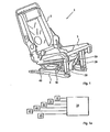
- FIG. 1 shows a vehicle seat 1 or seat 1 according to the invention with a backrest part 2 and a seat part 3, wherein the seat part 3 is connected to a seat base 4 via a front first attachment 20, a rear second attachment 40 and a diagonal attachment 30.
- the seat 1 according to the invention is provided in particular largely symmetrical with respect to its longitudinal axis, so that in an advantageous embodiment of the seat 1 both the front first attachment 20 and the second attachment 40 and the diagonal attachment 30 both on the left side and on the right side of Seat 1 are provided.
- the following is spoken without differentiation of the two sides of the seat 1 of the fasteners 20, 30 and 40 in the singular, but in each case both sides of a respective attachment 20, 30 and 40 are meant.
- FIG. 1a schematically illustrated the controller 10, which is connected to a triggering means 21, a first monitoring means 31, a first actuator 32, a second monitoring means 41, a second actuator 42 and an actuating means 43.
- the actuators 32, 42 of the second attachment 40 and the diagonal attachment 30 depending on the states of the triggering means 21 and the monitoring means 31, 41 and the actuating means 43, that is, in particular, the existing locking and / or unlocking state of Seat, controlled.
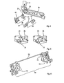
- FIG. 2 are various components of the seat according to the invention in an enlarged view, which is enlarged in size, shown.
- the seat part 3 not fully shown, only a side frame 3b is shown, on which the triggering means 21 can be seen.
- the second attachment 40 and the diagonal attachment 30 are shown with their individual parts.
- the second attachment 40 includes the second actuator 42 and the second Monitoring means 41.
- the diagonal fastening 30 comprises the first actuator 32 and the first monitoring means 31.
- an operating part 23 connected to the backrest part 2, which is moved by a movement of the backrest part 2 and actuates the release means 21 when the backrest part 2 is folded forwards.
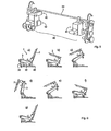
- FIG. 3 a section of the side part 3b of the seat part 3 is shown with attached release means 21, wherein in a left part of the FIG. 3 the depending on the position of the backrest or the backrest part 2 moving actuating member 23 cooperates with the release means 21 so that the release means 21 signals a Nachvorneklappen the backrest part 2 in its folded position.
- the actuating member 23 is provided corresponding to the normal position of the backrest part 2, so that the actuating member 23 does not cooperate with the triggering means 21 and signals the folding position of the backrest part 2.
- the diagonal mounting 30 is shown with its first actuator 32, its first monitoring means 31 and an adjusting bracket 34, on which the first actuator 32 acts.
- the first actuator 32 acts on the adjusting yoke 34 of the diagonal fastening 30, the diagonal fastening 30 is released and, according to the invention, can be displaced in particular longitudinally.
- the second attachment 40 is shown, the second attachment 40 comprising the second actuator 42, the second monitoring means 41 and also an adjustment bracket 44, on which - analogous to the diagonal attachment 30 - the second actuator 42 acts.
- the second attachment 40 is released and in particular the seat part 3 relative to the seat base 4 release, so that the seat 1 and the backrest part 2 together with the seat part 3 to the front first attachment 20 around, or around a rotation axis in the region of the front first attachment 20 is rotatably provided.
- FIG. 6a to FIG. 6g a sequence of positions of the seat 1 according to the invention is shown to the adjustment of the seat 1 from its normal position in to illustrate his boarding position and back to his normal position.
- the description of the various components of the seat in each case of these sub-figures has been omitted for the sake of simplicity.
- FIG. 6a the seat 1 is shown in its normal position.
- the seat 1 is in FIG. 6b shown with backrest folded backrest part 2.
- the release means 21 is activated, so that the second actuator 42 can provide a release of the seat part 3 in the region of the second attachment 40, which in FIG. 6c is shown.
- FIG. 6d the Einsteigeposition of the seat 1 is shown.
- FIG. 6e the movement of the seat 1 or its backrest part 2 and its seat part 3 is shown back to the normal position, wherein in FIG. 6f a latching of the second attachment 40 takes place, so that the seat part 3 is in turn firmly connected to the seat base 4.
- FIG. 6g the seat 1 is shown in its normal position.
- FIG. 7a to Figure 7g a sequence of positions of the seat 1 according to the invention is shown to illustrate the adjustment of the seat 1 from its normal position to its lowered position and back to its normal position.
- the description of the various components of the seat in each case of these sub-figures has been omitted for the sake of simplicity.
- the seat 1 is shown in its normal position.
- a user by means of the control means 10 connected to the actuating means 43, which, however, in the figures - except schematically in FIG. 1a - Not shown, can initiate the setting of the sinking position.
- the user actuates the actuating means 43, such as a button, touch screen or the like, whereby the controller 10 is signaled that the user intends to adjust the seat 1 in the retractable position.
- the actuating means 43 can therefore be distinguished between the user's request of the adjustment of the seat in the Einsteigeposition and in the sinking position.
- the seat 1 is in FIG. 7b shown with backrest folded backrest part 2.
- the triggering means 21 is activated, so that - because of the previous operation of the actuating means 43 - the first actuator 32 can allow a longitudinal displacement of the diagonal fastening 30, their beginning in FIG. 7c is shown and their complete shift in FIG. 7d is shown.
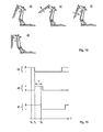
- FIG. 1 shows a first sequence of positions of a seat to illustrate the adjustment of the seat from the lowered position to an unauthorized position which abuses the large adjustment possibilities of a seat.
- the diagonal fastening 30 is adjusted longitudinally displaced. If, in this situation, the backrest part 2 erected (see. FIG. 8b ) is - with the triggering means 21 is turned off - and subsequently set back into its folding position (see. FIG. 8c ) - the triggering means 21 is actuated again by the actuating member 23 and it is initiated by the controller 10, a release or a solution of the second attachment 40 -, it is possible that by the solution of the second attachment 40 (see.
- FIG. 8d Nachvorneklappen of the seat 1 about a lying in the region of the first attachment 20 axis of rotation despite the course in the retracted position not locked diagonal attachment 30 is conceivable.
- Such misuse of the adjustment options is prevented according to the invention in that the first monitoring means 31 are attached to the diagonal attachment 30, which are actuated by the solution of the diagonal attachment 30 in the retractable position and when actuated, a solution of the second attachment, ie a control of the second actuator 42, prevent.
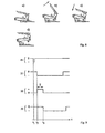
- FIG. 9 is that in FIG. 8 illustrated monitoring principle to prevent the abuse shown in a seat 1 according to the invention again illustrated by a logic diagram.
- four lines are given which represent states of various components of the seat 1 according to the invention. Each line represents the time course t of the state of the respective component. The designation "0" means that the corresponding component is inactive or not actuated.
- the first line relates to the actuating means 43, the second line relates to the triggering means 21, the third line relates to the first actuator 32 and the fourth line relates to the first monitoring means 31.
- the actuating means 43 is activated by a user operation.
- the backrest part 2 is set in its folding position.
- the triggering means 21 When the folding position is reached, the triggering means 21 is thereby activated (by means of the actuating part 23), which is the case at the second time t2.
- the controller 10 activates the first actuator 32 during a predetermined time interval T of, for example, 500 ms in order to enable the sinking position to be reached.
- T a predetermined time interval
- the first monitoring means 31 When the first actuator 32 has released the adjustment yoke 34 of the diagonal attachment 30, the first monitoring means 31 is activated at the third time t3.
- the controller 10 is now provided according to the invention such that a subsequent activation of the second actuator 42 is omitted as long as the first monitoring means signals an unlocking of the diagonal attachment 30 and this also for the case that the triggering means 21 - possibly by in the FIG. 8 shown adjustment operations of the backrest part 2 - is actuated again and could in principle cause a release of the second attachment 40 by activation of the second actuator 42.
- FIG. 10a to FIG. 10d a second sequence of positions of a seat is shown to illustrate the adjustment of the seat from the boarding position to an unauthorized and the large adjustment of a seat abusing position.
- the second attachment 40 is provided loosely, that is, the backrest part 2 and the seat part 3 can be folded around an axis of rotation in the region of the first attachment 20 forward. If, in this situation, the backrest part 2 erected (see. FIG. 10b ) is - with the triggering means 21 is turned off - and subsequently set back into its folding position (see. FIG.
- FIG. 11 is that in FIG. 10 illustrated monitoring principle to prevent the abuse shown in a seat 1 according to the invention again illustrated by a logic diagram.
- three lines are given, representing the states of various components of the seat 1 according to the invention. Each line represents the time course t of the state of the respective component. The designation "0" means that the corresponding component is inactive or not actuated.
- the first line relates to the triggering means 21, the second line relates to the second actuator 42 and the third line relates to the second monitoring means 41.
- the backrest is adjusted by a mechanical unlocking of the locking of the backrest part 2. As a result, the backrest part 2 is set in its folding position.
- the triggering means 21 is thereby activated (by means of the actuating part 23), which is the case at the fifth time t5.
- the controller 10 activates the second actuator 42 during a predetermined time interval T of, for example, 500 ms in order to enable the reaching in position to be reached.
- the second monitoring means 41 is activated at the same time t6.
- the control is 10 according to the invention provided such that a subsequent activation of the first actuator 32 is omitted as long as the second monitoring means 41 signals an unlocking of the second attachment 40 and this also for the case that the triggering means 21 - possibly by in the FIG. 10 illustrated adjusting operations of the Lehnenteils 2 - is actuated again and in principle could cause a release of the diagonal fastening 30 by activation of the first actuator 32.
- the release means 21 and the monitoring means 31, 41 are inventively provided in particular as a contact switch or as a micro-switch, which are switched mechanically by the movement of certain components.
- Representative of these components is the actuating member 23 for actuating the triggering means 21.
- a part of the tripping or monitoring means 21, 31, 41 perform a monitoring of the condition, while others carry out a monitoring of changes.
- the triggering means 21 responds to "flanks" or is evaluated by the control device 10 on "flanks" of its signal, while the first and second monitoring means 31, 41 only react to detected states, i. be evaluated by the controller 10 exclusively for instantaneous signals. From the latter there is the advantage that the evaluation of the monitoring means 31, 41 is independent of the movement history of the seat and thus an increased robustness of the system is given, for example, during power outages.
Landscapes
- Engineering & Computer Science (AREA)
- Aviation & Aerospace Engineering (AREA)
- Transportation (AREA)
- Mechanical Engineering (AREA)
- Seats For Vehicles (AREA)
- Chemical And Physical Treatments For Wood And The Like (AREA)
Claims (6)
- Siège (1), en particulier siège de véhicule automobile, avec une partie de dossier (2) et avec une partie d'assise (3), dans lequel il est prévu que la partie de dossier (2) puisse se rabattre d'une position normale à une position rabattue et inversement par rapport à la partie d'assise (3), dans lequel le siège (1) présente une infrastructure de siège (4), dans lequel il est prévu que la partie d'assise (3) soit mobile par rapport à l'infrastructure de siège (4), dans lequel il est prévu, pour la fixation de la partie d'assise (3) à l'infrastructure de siège (4), au moins une première fixation antérieure (20), une deuxième fixation postérieure (40) et une fixation diagonale (30), dans lequel il est prévu que le siège (1) soit réglable dans au moins une position d'embarquement et dans une position d'escamotage, en plus d'une position normale, dans lequel il est prévu que la deuxième fixation (40) soit débloquée dans la position d'embarquement et dans lequel il est prévu que la fixation diagonale (30) soit débloquée dans la position d'escamotage, caractérisé en ce qu'il est prévu des moyens de déblocage (21), dans lequel les moyens de déblocage (21) provoquent, lorsque le dossier (2) se trouve dans sa position rabattue, un déblocage soit de la fixation diagonale (30) soit de la deuxième fixation (40) uniquement pendant un intervalle de temps prédéterminé (T).
- Siège (1) selon la revendication 1, caractérisé en ce qu'il est prévu que, dans la position d'embarquement, la partie d'assise (3) soit séparée de l'infrastructure de siège (4) dans la région de la deuxième fixation (40) et/ou que, dans la position d'escamotage, la fixation diagonale (30) soit déplacée longitudinalement par rapport à son réglage dans la position normale.
- Siège (1) selon l'une quelconque des revendications précédentes, caractérisé en ce qu'il est prévu un deuxième actionneur (42) pour la séparation de la partie d'assise (3) dans la région de la deuxième fixation (40) et/ou en ce qu'il est prévu un premier actionneur (32) pour le déplacement longitudinal de la fixation diagonale (30), dans lequel le premier et/ou le deuxième actionneur (32, 42) sont prévus en particulier sous la forme d'actionneurs à moteur électrique.
- Siège (1) selon l'une quelconque des revendications précédentes, caractérisé en ce qu'il est prévu des premiers moyens de surveillance (31), dans lequel les premiers moyens de surveillance provoquent un empêchement de déblocage de la fixation diagonale (30) dans la position d'embarquement et/ou en ce qu'il est prévu des deuxièmes moyens de surveillance (41), dans lequel les deuxièmes moyens de surveillance (41) provoquent un empêchement de déblocage de la deuxième fixation (40) dans la position d'escamotage.
- Siège (1) selon la revendication 4, caractérisé en ce que les premiers moyens de surveillance (31) et/ou les deuxièmes moyens de surveillance (41) et/ou les moyens de déblocage (21) sont prévus sous la forme de micro-interrupteurs.
- Siège (1) selon l'une quelconque des revendications précédentes, caractérisé en ce que le siège (1) comporte un dispositif de commande (10) pour la commande du déblocage des fixations (20, 30, 40) en fonction de l'état existant de verrouillage et/ou de déverrouillage.
Priority Applications (1)
| Application Number | Priority Date | Filing Date | Title |
|---|---|---|---|
| PL04764898T PL1663703T3 (pl) | 2003-09-09 | 2004-09-07 | Fotel i sposób |
Applications Claiming Priority (2)
| Application Number | Priority Date | Filing Date | Title |
|---|---|---|---|
| DE10341375A DE10341375B4 (de) | 2003-09-09 | 2003-09-09 | Sitz, insbesondere Kraftfahrzeugsitz |
| PCT/EP2004/009955 WO2005025931A1 (fr) | 2003-09-09 | 2004-09-07 | Siege et procede associe |
Publications (2)
| Publication Number | Publication Date |
|---|---|
| EP1663703A1 EP1663703A1 (fr) | 2006-06-07 |
| EP1663703B1 true EP1663703B1 (fr) | 2011-08-10 |
Family
ID=34258495
Family Applications (1)
| Application Number | Title | Priority Date | Filing Date |
|---|---|---|---|
| EP04764898A Expired - Lifetime EP1663703B1 (fr) | 2003-09-09 | 2004-09-07 | Siege et procede associe |
Country Status (7)
| Country | Link |
|---|---|
| US (1) | US7802850B2 (fr) |
| EP (1) | EP1663703B1 (fr) |
| JP (1) | JP4722046B2 (fr) |
| AT (1) | ATE519621T1 (fr) |
| DE (1) | DE10341375B4 (fr) |
| PL (1) | PL1663703T3 (fr) |
| WO (1) | WO2005025931A1 (fr) |
Families Citing this family (10)
| Publication number | Priority date | Publication date | Assignee | Title |
|---|---|---|---|---|
| US7552972B2 (en) | 2005-06-02 | 2009-06-30 | Lear Corporation | Power assist fold and tumble vehicle seat |
| US7699399B2 (en) * | 2005-08-30 | 2010-04-20 | Aisin Seiki Kabushiki Kaisha | Seat apparatus |
| JP5309746B2 (ja) * | 2008-07-15 | 2013-10-09 | トヨタ紡織株式会社 | 車両用シート |
| JP5751083B2 (ja) | 2011-08-11 | 2015-07-22 | トヨタ紡織株式会社 | 車両用シート |
| DE102011084087B4 (de) | 2011-10-06 | 2020-06-04 | Bayerische Motoren Werke Aktiengesellschaft | Verstellvorrichtung zur ergonomischen Einstellung eines Fahrzeugsitzes mit mehreren verstellbaren Sitzkomponenten und/oder zur ergonomischen Einstellung von sitzpositionsabhängigen verstellbaren Fahrzeugkomponenten |
| FR3071447B1 (fr) | 2017-09-22 | 2020-05-22 | Faurecia Sieges D'automobile | Siege a basculement automatique |
| DE102018112926B4 (de) * | 2018-05-30 | 2022-04-14 | Adient Engineering and IP GmbH | Fahrzeugsitz |
| US11351891B2 (en) * | 2018-09-27 | 2022-06-07 | Faurecia Sièges d'Automobile | System comprising a vehicle seat with tilting backrest |
| FR3101290B1 (fr) * | 2019-09-30 | 2022-12-23 | Faurecia Sieges Dautomobile | Siège de véhicule |
| CN219270552U (zh) * | 2023-02-18 | 2023-06-30 | 顾家家居股份有限公司 | 一种具有靠背翻折功能的沙发 |
Family Cites Families (25)
| Publication number | Priority date | Publication date | Assignee | Title |
|---|---|---|---|---|
| JPS57165529A (en) * | 1981-04-04 | 1982-10-12 | Koichi Miura | Construction of strip footing |
| JPS6056648B2 (ja) * | 1981-09-01 | 1985-12-11 | マツダ株式会社 | 自動車用シ−ト |
| JPS61202941A (ja) * | 1985-03-04 | 1986-09-08 | Nippon Soken Inc | パワ−シ−ト畳み込み制御装置 |
| DE3801294C2 (de) * | 1988-01-19 | 1995-01-19 | Daimler Benz Ag | Klappbarer Fahrzeugsitz |
| DE4220661C2 (de) * | 1992-06-24 | 1997-07-31 | Man Nutzfahrzeuge Ag | Vorklappbarer Reisebegleitsitz in Omnibussen |
| CA2111725C (fr) * | 1993-12-18 | 1998-10-13 | Wojciech Smuk | Mecanisme permettant d'incliner et de replier des sieges d'automobiles |
| DE29715345U1 (de) * | 1997-08-27 | 1998-12-24 | Johnson Controls GmbH, 51399 Burscheid | Sitzkonstruktion insbesondere für Kfz-Rücksitze |
| US6012755A (en) * | 1997-10-15 | 2000-01-11 | Lear Corporation | Foldable automotive seat |
| BR9911971A (pt) * | 1998-07-14 | 2001-03-27 | Magna Interior Sys Inc | Montagens de assento de automóveis e de elevação de assento |
| US6000742A (en) * | 1999-02-01 | 1999-12-14 | Ford Motor Company | Multi-positional seat mounting apparatus |
| US6024411A (en) * | 1999-03-17 | 2000-02-15 | Daimlerchrysler Corporation | Seat mounted cupholder adapted for seat riser fold and tumble mechanism |
| DE19964143C2 (de) * | 1999-09-11 | 2001-07-12 | Keiper Gmbh & Co | Fahrzeugsitz mit Packagestellung |
| US6174017B1 (en) * | 1999-11-04 | 2001-01-16 | Daimlerchrysler Corporation | Dumping and articulating seat |
| US6131999A (en) * | 1999-11-22 | 2000-10-17 | Ford Motor Company | Folding vehicle seat assembly |
| US6135555A (en) * | 1999-11-22 | 2000-10-24 | Ford Motor Company | Tumbling vehicle seat assembly |
| US6793285B1 (en) * | 2000-03-13 | 2004-09-21 | Magna Seating Systems Inc. | Safety mechanism for a fold and tumble seat assembly |
| US6590354B2 (en) * | 2000-10-19 | 2003-07-08 | Lear Corporation | Seat adjusting system having motor with integrated sensor and control electronics |
| DE10056024C2 (de) | 2000-11-11 | 2002-10-31 | Bosch Gmbh Robert | Personenkraftwagen mit Fondsitzen |
| DE10130813C2 (de) * | 2001-06-26 | 2003-06-05 | Keiper Gmbh & Co Kg | Fahrzeugsitz mit Bodenstellung |
| DE10136244C1 (de) * | 2001-07-25 | 2002-08-29 | Keiper Gmbh & Co | Fahrzeugsitz, insbesondere Kraftfahrzeugsitz |
| DE10139538C1 (de) * | 2001-08-10 | 2003-03-20 | Faurecia Autositze Gmbh & Co | Fondsitz für Kraftfahrzeuge |
| JP3597497B2 (ja) * | 2001-10-16 | 2004-12-08 | 本田技研工業株式会社 | 車両用シート |
| US7118178B2 (en) * | 2002-11-06 | 2006-10-10 | Intier Automotive Inc, | Power folding seat |
| US6857703B2 (en) * | 2002-11-05 | 2005-02-22 | Fisher Dynamics Corporation | Fold, tumble and kneel seat assembly |
| US7959230B2 (en) * | 2003-04-11 | 2011-06-14 | Johnson Controls Technology Company | Seating system for a vehicle |
-
2003
- 2003-09-09 DE DE10341375A patent/DE10341375B4/de not_active Expired - Fee Related
-
2004
- 2004-09-07 US US10/571,185 patent/US7802850B2/en not_active Expired - Fee Related
- 2004-09-07 AT AT04764898T patent/ATE519621T1/de active
- 2004-09-07 WO PCT/EP2004/009955 patent/WO2005025931A1/fr not_active Ceased
- 2004-09-07 PL PL04764898T patent/PL1663703T3/pl unknown
- 2004-09-07 JP JP2006525737A patent/JP4722046B2/ja not_active Expired - Fee Related
- 2004-09-07 EP EP04764898A patent/EP1663703B1/fr not_active Expired - Lifetime
Also Published As
| Publication number | Publication date |
|---|---|
| ATE519621T1 (de) | 2011-08-15 |
| US7802850B2 (en) | 2010-09-28 |
| PL1663703T3 (pl) | 2012-01-31 |
| EP1663703A1 (fr) | 2006-06-07 |
| DE10341375A1 (de) | 2005-04-07 |
| JP4722046B2 (ja) | 2011-07-13 |
| DE10341375B4 (de) | 2005-09-29 |
| US20070236068A1 (en) | 2007-10-11 |
| WO2005025931A1 (fr) | 2005-03-24 |
| JP2007504990A (ja) | 2007-03-08 |
Similar Documents
| Publication | Publication Date | Title |
|---|---|---|
| EP0826855B1 (fr) | Serrure, spécialement pour portes de véhicules ou similaires | |
| DE102005051298B4 (de) | Sitzanordnung für ein Fahrzeug | |
| EP1997997A2 (fr) | Procédé de réglage motorisé d'une porte de véhicule automobile | |
| EP1078807B1 (fr) | Dispositif de réglage éléctrique pour le siège d'un véhicule automobile | |
| EP1178897B1 (fr) | Dispositif servant a commander des moteurs de positionnement pour le reglage de differentes parties d'un siege | |
| EP1663703B1 (fr) | Siege et procede associe | |
| DE102016207524A1 (de) | Verstelleinrichtung für einen Fahrzeugsitz und Steuerungsverfahren | |
| DE19631454C2 (de) | Fahrzeugsitz mit einer Sitzplatte und einer Rückenlehne | |
| DE102019001066A1 (de) | Sitzanlage für einen lnnenraum eines Kraftwagens | |
| DE102013224282A1 (de) | Automatisches Verfahren eines durch Fremdkraft verfahrbaren Sitzes eines Personenkraftwagens bei Dauerbetätigung des Türaußengriffes | |
| DE19630223C2 (de) | Verstelleinrichtung für einen Vordersitz eines Kraftfahrzeugs | |
| DE102004033222B4 (de) | Sitzverstellung | |
| DE19951120C2 (de) | Vorrichtung und Verfahren zur Erleichterung des Ein- und/oder Aussteigens zu bzw. von einem Fondsitz eines viertürigen Kraftfahrzeuges | |
| EP0257538B2 (fr) | Arrangement des interrupteurs dans des véhicules à moteur | |
| DE102004061141A1 (de) | Türzuziehgriff | |
| DE102013000164A1 (de) | Fahrzeugsitz, insbesondere für einen Pkw | |
| WO2006092210A2 (fr) | Vehicule automobile | |
| DE102016114884A1 (de) | Kraftfahrzeuginnenraumanordnung mit einer Betätigungseinrichtung für ein Arretiersystem | |
| DE102017101075B4 (de) | Verfahren zur Verlagerung eines Kraftfahrzeugsitzes mit Easy-Entry-Funktion | |
| DE3447039C2 (de) | Zentralverriegelung für Kraftfahrzeuge | |
| DE102004048821B4 (de) | Vorrichtung und Verfahren zum Verstellen einer Fahrzeugkomponente | |
| EP1681198B1 (fr) | Dispositif pour permettre l'accés à un espace clos de l'intérieur d'un véhicule automobile | |
| DE69600339T2 (de) | Vorrichtung zur Steuerung einer elektrisch bedienbaren Schiebedacheinrichtung für Kraftfahrzeug | |
| DE19711369B4 (de) | Bedienvorrichtung für ein Fahrzeug mit Fernbedienung der Beifahrerseite | |
| DE102004010592A1 (de) | Cockpit eines Kraftfahrzeugs mit einem Lenkrad und einem verstellbaren Sitz |
Legal Events
| Date | Code | Title | Description |
|---|---|---|---|
| PUAI | Public reference made under article 153(3) epc to a published international application that has entered the european phase |
Free format text: ORIGINAL CODE: 0009012 |
|
| 17P | Request for examination filed |
Effective date: 20060321 |
|
| AK | Designated contracting states |
Kind code of ref document: A1 Designated state(s): AT BE BG CH CY CZ DE DK EE ES FI FR GB GR HU IE IT LI LU MC NL PL PT RO SE SI SK TR |
|
| DAX | Request for extension of the european patent (deleted) | ||
| 17Q | First examination report despatched |
Effective date: 20081110 |
|
| GRAP | Despatch of communication of intention to grant a patent |
Free format text: ORIGINAL CODE: EPIDOSNIGR1 |
|
| GRAS | Grant fee paid |
Free format text: ORIGINAL CODE: EPIDOSNIGR3 |
|
| GRAA | (expected) grant |
Free format text: ORIGINAL CODE: 0009210 |
|
| AK | Designated contracting states |
Kind code of ref document: B1 Designated state(s): AT BE BG CH CY CZ DE DK EE ES FI FR GB GR HU IE IT LI LU MC NL PL PT RO SE SI SK TR |
|
| REG | Reference to a national code |
Ref country code: GB Ref legal event code: FG4D Free format text: NOT ENGLISH |
|
| REG | Reference to a national code |
Ref country code: CH Ref legal event code: EP |
|
| REG | Reference to a national code |
Ref country code: DE Ref legal event code: R081 Ref document number: 502004012784 Country of ref document: DE Owner name: ADIENT LUXEMBOURG HOLDING S.A.R.L., LU Free format text: FORMER OWNER: JOHNSON CONTROLS GMBH, 51399 BURSCHEID, DE Ref country code: DE Ref legal event code: R081 Ref document number: 502004012784 Country of ref document: DE Owner name: ADIENT LUXEMBOURG HOLDING S.A R.L., LU Free format text: FORMER OWNER: JOHNSON CONTROLS GMBH, 51399 BURSCHEID, DE |
|
| REG | Reference to a national code |
Ref country code: IE Ref legal event code: FG4D Free format text: LANGUAGE OF EP DOCUMENT: GERMAN |
|
| REG | Reference to a national code |
Ref country code: DE Ref legal event code: R096 Ref document number: 502004012784 Country of ref document: DE Effective date: 20111006 |
|
| REG | Reference to a national code |
Ref country code: NL Ref legal event code: VDEP Effective date: 20110810 |
|
| REG | Reference to a national code |
Ref country code: SK Ref legal event code: T3 Ref document number: E 10366 Country of ref document: SK |
|
| PG25 | Lapsed in a contracting state [announced via postgrant information from national office to epo] |
Ref country code: NL Free format text: LAPSE BECAUSE OF FAILURE TO SUBMIT A TRANSLATION OF THE DESCRIPTION OR TO PAY THE FEE WITHIN THE PRESCRIBED TIME-LIMIT Effective date: 20110810 Ref country code: SE Free format text: LAPSE BECAUSE OF FAILURE TO SUBMIT A TRANSLATION OF THE DESCRIPTION OR TO PAY THE FEE WITHIN THE PRESCRIBED TIME-LIMIT Effective date: 20110810 Ref country code: FI Free format text: LAPSE BECAUSE OF FAILURE TO SUBMIT A TRANSLATION OF THE DESCRIPTION OR TO PAY THE FEE WITHIN THE PRESCRIBED TIME-LIMIT Effective date: 20110810 Ref country code: PT Free format text: LAPSE BECAUSE OF FAILURE TO SUBMIT A TRANSLATION OF THE DESCRIPTION OR TO PAY THE FEE WITHIN THE PRESCRIBED TIME-LIMIT Effective date: 20111212 |
|
| REG | Reference to a national code |
Ref country code: PL Ref legal event code: T3 |
|
| PG25 | Lapsed in a contracting state [announced via postgrant information from national office to epo] |
Ref country code: SI Free format text: LAPSE BECAUSE OF FAILURE TO SUBMIT A TRANSLATION OF THE DESCRIPTION OR TO PAY THE FEE WITHIN THE PRESCRIBED TIME-LIMIT Effective date: 20110810 Ref country code: CY Free format text: LAPSE BECAUSE OF FAILURE TO SUBMIT A TRANSLATION OF THE DESCRIPTION OR TO PAY THE FEE WITHIN THE PRESCRIBED TIME-LIMIT Effective date: 20110810 Ref country code: GR Free format text: LAPSE BECAUSE OF FAILURE TO SUBMIT A TRANSLATION OF THE DESCRIPTION OR TO PAY THE FEE WITHIN THE PRESCRIBED TIME-LIMIT Effective date: 20111111 |
|
| REG | Reference to a national code |
Ref country code: IE Ref legal event code: FD4D |
|
| BERE | Be: lapsed |
Owner name: JOHNSON CONTROLS G.M.B.H. Effective date: 20110930 |
|
| PG25 | Lapsed in a contracting state [announced via postgrant information from national office to epo] |
Ref country code: MC Free format text: LAPSE BECAUSE OF NON-PAYMENT OF DUE FEES Effective date: 20110930 Ref country code: IE Free format text: LAPSE BECAUSE OF FAILURE TO SUBMIT A TRANSLATION OF THE DESCRIPTION OR TO PAY THE FEE WITHIN THE PRESCRIBED TIME-LIMIT Effective date: 20110810 |
|
| REG | Reference to a national code |
Ref country code: CH Ref legal event code: PL |
|
| PG25 | Lapsed in a contracting state [announced via postgrant information from national office to epo] |
Ref country code: EE Free format text: LAPSE BECAUSE OF FAILURE TO SUBMIT A TRANSLATION OF THE DESCRIPTION OR TO PAY THE FEE WITHIN THE PRESCRIBED TIME-LIMIT Effective date: 20110810 Ref country code: RO Free format text: LAPSE BECAUSE OF FAILURE TO SUBMIT A TRANSLATION OF THE DESCRIPTION OR TO PAY THE FEE WITHIN THE PRESCRIBED TIME-LIMIT Effective date: 20110810 Ref country code: IT Free format text: LAPSE BECAUSE OF FAILURE TO SUBMIT A TRANSLATION OF THE DESCRIPTION OR TO PAY THE FEE WITHIN THE PRESCRIBED TIME-LIMIT Effective date: 20110810 |
|
| PLBE | No opposition filed within time limit |
Free format text: ORIGINAL CODE: 0009261 |
|
| STAA | Information on the status of an ep patent application or granted ep patent |
Free format text: STATUS: NO OPPOSITION FILED WITHIN TIME LIMIT |
|
| PG25 | Lapsed in a contracting state [announced via postgrant information from national office to epo] |
Ref country code: BE Free format text: LAPSE BECAUSE OF NON-PAYMENT OF DUE FEES Effective date: 20110930 Ref country code: DK Free format text: LAPSE BECAUSE OF FAILURE TO SUBMIT A TRANSLATION OF THE DESCRIPTION OR TO PAY THE FEE WITHIN THE PRESCRIBED TIME-LIMIT Effective date: 20110810 |
|
| 26N | No opposition filed |
Effective date: 20120511 |
|
| GBPC | Gb: european patent ceased through non-payment of renewal fee |
Effective date: 20111110 |
|
| PG25 | Lapsed in a contracting state [announced via postgrant information from national office to epo] |
Ref country code: CH Free format text: LAPSE BECAUSE OF NON-PAYMENT OF DUE FEES Effective date: 20110930 Ref country code: LI Free format text: LAPSE BECAUSE OF NON-PAYMENT OF DUE FEES Effective date: 20110930 |
|
| REG | Reference to a national code |
Ref country code: DE Ref legal event code: R097 Ref document number: 502004012784 Country of ref document: DE Effective date: 20120511 |
|
| PG25 | Lapsed in a contracting state [announced via postgrant information from national office to epo] |
Ref country code: GB Free format text: LAPSE BECAUSE OF NON-PAYMENT OF DUE FEES Effective date: 20111110 |
|
| REG | Reference to a national code |
Ref country code: AT Ref legal event code: MM01 Ref document number: 519621 Country of ref document: AT Kind code of ref document: T Effective date: 20110907 |
|
| PG25 | Lapsed in a contracting state [announced via postgrant information from national office to epo] |
Ref country code: AT Free format text: LAPSE BECAUSE OF NON-PAYMENT OF DUE FEES Effective date: 20110907 |
|
| PG25 | Lapsed in a contracting state [announced via postgrant information from national office to epo] |
Ref country code: ES Free format text: LAPSE BECAUSE OF FAILURE TO SUBMIT A TRANSLATION OF THE DESCRIPTION OR TO PAY THE FEE WITHIN THE PRESCRIBED TIME-LIMIT Effective date: 20111121 |
|
| PG25 | Lapsed in a contracting state [announced via postgrant information from national office to epo] |
Ref country code: LU Free format text: LAPSE BECAUSE OF NON-PAYMENT OF DUE FEES Effective date: 20110907 |
|
| PG25 | Lapsed in a contracting state [announced via postgrant information from national office to epo] |
Ref country code: BG Free format text: LAPSE BECAUSE OF FAILURE TO SUBMIT A TRANSLATION OF THE DESCRIPTION OR TO PAY THE FEE WITHIN THE PRESCRIBED TIME-LIMIT Effective date: 20111110 |
|
| PG25 | Lapsed in a contracting state [announced via postgrant information from national office to epo] |
Ref country code: TR Free format text: LAPSE BECAUSE OF FAILURE TO SUBMIT A TRANSLATION OF THE DESCRIPTION OR TO PAY THE FEE WITHIN THE PRESCRIBED TIME-LIMIT Effective date: 20110810 |
|
| PG25 | Lapsed in a contracting state [announced via postgrant information from national office to epo] |
Ref country code: HU Free format text: LAPSE BECAUSE OF FAILURE TO SUBMIT A TRANSLATION OF THE DESCRIPTION OR TO PAY THE FEE WITHIN THE PRESCRIBED TIME-LIMIT Effective date: 20110810 |
|
| REG | Reference to a national code |
Ref country code: FR Ref legal event code: PLFP Year of fee payment: 12 |
|
| REG | Reference to a national code |
Ref country code: FR Ref legal event code: PLFP Year of fee payment: 13 |
|
| PGFP | Annual fee paid to national office [announced via postgrant information from national office to epo] |
Ref country code: CZ Payment date: 20160823 Year of fee payment: 13 Ref country code: PL Payment date: 20160823 Year of fee payment: 13 Ref country code: SK Payment date: 20160906 Year of fee payment: 13 |
|
| REG | Reference to a national code |
Ref country code: DE Ref legal event code: R081 Ref document number: 502004012784 Country of ref document: DE Owner name: ADIENT LUXEMBOURG HOLDING S.A.R.L., LU Free format text: FORMER OWNER: JOHNSON CONTROLS GMBH, 51399 BURSCHEID, DE Ref country code: DE Ref legal event code: R081 Ref document number: 502004012784 Country of ref document: DE Owner name: ADIENT LUXEMBOURG HOLDING S.A R.L., LU Free format text: FORMER OWNER: JOHNSON CONTROLS GMBH, 51399 BURSCHEID, DE |
|
| REG | Reference to a national code |
Ref country code: FR Ref legal event code: PLFP Year of fee payment: 14 |
|
| PGFP | Annual fee paid to national office [announced via postgrant information from national office to epo] |
Ref country code: FR Payment date: 20170928 Year of fee payment: 14 |
|
| PGFP | Annual fee paid to national office [announced via postgrant information from national office to epo] |
Ref country code: DE Payment date: 20170930 Year of fee payment: 14 |
|
| REG | Reference to a national code |
Ref country code: DE Ref legal event code: R081 Ref document number: 502004012784 Country of ref document: DE Owner name: ADIENT LUXEMBOURG HOLDING S.A R.L., LU Free format text: FORMER OWNER: ADIENT LUXEMBOURG HOLDING S.A.R.L., LUXEMBOURG, LU |
|
| PG25 | Lapsed in a contracting state [announced via postgrant information from national office to epo] |
Ref country code: CZ Free format text: LAPSE BECAUSE OF NON-PAYMENT OF DUE FEES Effective date: 20170907 |
|
| REG | Reference to a national code |
Ref country code: SK Ref legal event code: MM4A Ref document number: E 10366 Country of ref document: SK Effective date: 20170907 |
|
| PG25 | Lapsed in a contracting state [announced via postgrant information from national office to epo] |
Ref country code: SK Free format text: LAPSE BECAUSE OF NON-PAYMENT OF DUE FEES Effective date: 20170907 |
|
| REG | Reference to a national code |
Ref country code: DE Ref legal event code: R119 Ref document number: 502004012784 Country of ref document: DE |
|
| PG25 | Lapsed in a contracting state [announced via postgrant information from national office to epo] |
Ref country code: PL Free format text: LAPSE BECAUSE OF NON-PAYMENT OF DUE FEES Effective date: 20170907 |
|
| PG25 | Lapsed in a contracting state [announced via postgrant information from national office to epo] |
Ref country code: DE Free format text: LAPSE BECAUSE OF NON-PAYMENT OF DUE FEES Effective date: 20190402 |
|
| PG25 | Lapsed in a contracting state [announced via postgrant information from national office to epo] |
Ref country code: FR Free format text: LAPSE BECAUSE OF NON-PAYMENT OF DUE FEES Effective date: 20180930 |