EP1663703B1 - Seat and method - Google Patents
Seat and method Download PDFInfo
- Publication number
- EP1663703B1 EP1663703B1 EP04764898A EP04764898A EP1663703B1 EP 1663703 B1 EP1663703 B1 EP 1663703B1 EP 04764898 A EP04764898 A EP 04764898A EP 04764898 A EP04764898 A EP 04764898A EP 1663703 B1 EP1663703 B1 EP 1663703B1
- Authority
- EP
- European Patent Office
- Prior art keywords
- seat
- fastening
- diagonal
- attachment
- monitoring means
- Prior art date
- Legal status (The legal status is an assumption and is not a legal conclusion. Google has not performed a legal analysis and makes no representation as to the accuracy of the status listed.)
- Expired - Lifetime
Links
- 238000000034 method Methods 0.000 title description 2
- 238000012544 monitoring process Methods 0.000 claims description 39
- 238000006073 displacement reaction Methods 0.000 description 5
- 201000009032 substance abuse Diseases 0.000 description 5
- 230000004913 activation Effects 0.000 description 4
- 238000010586 diagram Methods 0.000 description 4
- 230000002265 prevention Effects 0.000 description 2
- 241001244708 Moroccan pepper virus Species 0.000 description 1
- 238000010276 construction Methods 0.000 description 1
- 230000004069 differentiation Effects 0.000 description 1
- 230000000694 effects Effects 0.000 description 1
- 238000011156 evaluation Methods 0.000 description 1
- 238000003780 insertion Methods 0.000 description 1
- 230000037431 insertion Effects 0.000 description 1
Images

Classifications
-
- B—PERFORMING OPERATIONS; TRANSPORTING
- B60—VEHICLES IN GENERAL
- B60N—SEATS SPECIALLY ADAPTED FOR VEHICLES; VEHICLE PASSENGER ACCOMMODATION NOT OTHERWISE PROVIDED FOR
- B60N2/00—Seats specially adapted for vehicles; Arrangement or mounting of seats in vehicles
- B60N2/02—Seats specially adapted for vehicles; Arrangement or mounting of seats in vehicles the seat or part thereof being movable, e.g. adjustable
- B60N2/0224—Non-manual adjustments, e.g. with electrical operation
- B60N2/02246—Electric motors therefor
-
- B—PERFORMING OPERATIONS; TRANSPORTING
- B60—VEHICLES IN GENERAL
- B60N—SEATS SPECIALLY ADAPTED FOR VEHICLES; VEHICLE PASSENGER ACCOMMODATION NOT OTHERWISE PROVIDED FOR
- B60N2/00—Seats specially adapted for vehicles; Arrangement or mounting of seats in vehicles
- B60N2/24—Seats specially adapted for vehicles; Arrangement or mounting of seats in vehicles for particular purposes or particular vehicles
- B60N2/30—Non-dismountable or dismountable seats storable in a non-use position, e.g. foldable spare seats
- B60N2/3002—Non-dismountable or dismountable seats storable in a non-use position, e.g. foldable spare seats back-rest movements
- B60N2/3004—Non-dismountable or dismountable seats storable in a non-use position, e.g. foldable spare seats back-rest movements by rotation only
- B60N2/3009—Non-dismountable or dismountable seats storable in a non-use position, e.g. foldable spare seats back-rest movements by rotation only about transversal axis
- B60N2/3011—Non-dismountable or dismountable seats storable in a non-use position, e.g. foldable spare seats back-rest movements by rotation only about transversal axis the back-rest being hinged on the cushion, e.g. "portefeuille movement"
-
- B—PERFORMING OPERATIONS; TRANSPORTING
- B60—VEHICLES IN GENERAL
- B60N—SEATS SPECIALLY ADAPTED FOR VEHICLES; VEHICLE PASSENGER ACCOMMODATION NOT OTHERWISE PROVIDED FOR
- B60N2/00—Seats specially adapted for vehicles; Arrangement or mounting of seats in vehicles
- B60N2/24—Seats specially adapted for vehicles; Arrangement or mounting of seats in vehicles for particular purposes or particular vehicles
- B60N2/30—Non-dismountable or dismountable seats storable in a non-use position, e.g. foldable spare seats
- B60N2/3038—Cushion movements
- B60N2/304—Cushion movements by rotation only
- B60N2/3045—Cushion movements by rotation only about transversal axis
- B60N2/305—Cushion movements by rotation only about transversal axis the cushion being hinged on the vehicle frame
-
- B—PERFORMING OPERATIONS; TRANSPORTING
- B60—VEHICLES IN GENERAL
- B60N—SEATS SPECIALLY ADAPTED FOR VEHICLES; VEHICLE PASSENGER ACCOMMODATION NOT OTHERWISE PROVIDED FOR
- B60N2/00—Seats specially adapted for vehicles; Arrangement or mounting of seats in vehicles
- B60N2/24—Seats specially adapted for vehicles; Arrangement or mounting of seats in vehicles for particular purposes or particular vehicles
- B60N2/30—Non-dismountable or dismountable seats storable in a non-use position, e.g. foldable spare seats
- B60N2/3038—Cushion movements
- B60N2/3063—Cushion movements by composed movement
- B60N2/3065—Cushion movements by composed movement in a longitudinal-vertical plane
-
- B—PERFORMING OPERATIONS; TRANSPORTING
- B60—VEHICLES IN GENERAL
- B60N—SEATS SPECIALLY ADAPTED FOR VEHICLES; VEHICLE PASSENGER ACCOMMODATION NOT OTHERWISE PROVIDED FOR
- B60N2/00—Seats specially adapted for vehicles; Arrangement or mounting of seats in vehicles
- B60N2/24—Seats specially adapted for vehicles; Arrangement or mounting of seats in vehicles for particular purposes or particular vehicles
- B60N2/30—Non-dismountable or dismountable seats storable in a non-use position, e.g. foldable spare seats
- B60N2/3088—Non-dismountable or dismountable seats storable in a non-use position, e.g. foldable spare seats characterised by the mechanical link
- B60N2/309—Non-dismountable or dismountable seats storable in a non-use position, e.g. foldable spare seats characterised by the mechanical link rods
-
- B—PERFORMING OPERATIONS; TRANSPORTING
- B60—VEHICLES IN GENERAL
- B60N—SEATS SPECIALLY ADAPTED FOR VEHICLES; VEHICLE PASSENGER ACCOMMODATION NOT OTHERWISE PROVIDED FOR
- B60N2/00—Seats specially adapted for vehicles; Arrangement or mounting of seats in vehicles
- B60N2/90—Details or parts not otherwise provided for
- B60N2/919—Positioning and locking mechanisms
- B60N2002/952—Positioning and locking mechanisms characterised by details of the locking system
- B60N2002/957—Positioning and locking mechanisms characterised by details of the locking system the locking system prevents an abnormal or wrong mounting situation, i.e. deployment or functioning of a seat part being prevented if the seat or seat part is not properly mounted
Definitions
- the invention relates to a seat, in particular a vehicle seat, according to the preamble of claim 1.
- a seat in particular a vehicle seat
- this has the effect that, for example, as a boarding aid in a motor vehicle for users of the motor vehicle who want to sit on the rear seat of a motor vehicle, the back of a seat located in front of the rear seat forward, i. away from the rear seat, to be folded.
- vans especially so-called "vans” or "MPVs”
- it is advantageous that further functional possibilities or positions of vehicle seats are possible, for example, the back of such a seat can be folded forward so that the back of the Backrest can be used as a table.
- vehicle seats which, especially in vehicles which do not have separate doors as access for a rear seat bench, have a backrest such that the backrest of the vehicle seat is folded forward for the easier entry of passengers onto the rear bench seat.
- a mechanical unlocking device is usually operated manually, so that the backrest, which is provided locked in its normal position in a certain, adjustable angle of inclination to the seat, can be folded forward.
- the entire seat substructure remains in the same position, ie remains in the same place, and thus is still a hindrance to boarding passengers.
- Such vehicle seats are for example from the publications DE 101 39 538 C1 . DE 297 15 345 U . DE 100 56 024 A . EP 0 575 733 A and DE 101 36 244 C known, in which case from a generic seat of the DE 101 39 538 C1 is assumed.
- the invention is therefore based on the object to provide a seat, in particular a vehicle seat, which has a maximum of possible variations in terms of its intended for different situations of use adjustment positions.
- the invention provides a Abuse of the setting options or to prevent an unintended combination of setting options.
- a seat according to claim 1 This results in a maximum of adjustment that leads to an increase in the ease of use when using the seat and the motor vehicle. Furthermore, it is advantageous that release means are provided, wherein the release means cause a solution of either the diagonal attachment or the second attachment only during a predetermined time interval when located in its folding position backrest. As a result, abuses of use of the seat continue to be limited.
- the seat part in the entry position, is provided separately from the seat base in the region of the second attachment and / or the diagonal attachment is longitudinally displaced in the lowered position relative to its setting in the normal position.
- a second actuator is provided for separating the seat part in the region of the second fastening and / or that a first actuator is provided for longitudinal displacement of the diagonal fastening, wherein the first and / or the second actuator are provided in particular as electromotive actuators.
- this causes the possibility of the various adjustment options of the seat can be made automated or controlled and thus eliminates a direct release by a user, which on the one hand facilitates the use, for example, does not have to be handled in inaccessible places of the seat , and on the other hand simplified the construction of the seat and thus cheaper, because no unwieldy and weight-causing handles, levers or other actuators must be provided.
- first monitoring means are provided, wherein the first monitoring means cause a prevention of the solution of the diagonal fastening in the boarding position and / or the second monitoring means are provided, but wherein the second monitoring means cause a prevention of the solution of the second attachment in the sinking position ,
- first monitoring means and / or the second monitoring means and / or the triggering means are provided as micro-switches. This makes it possible in a particularly simple and cost-effective manner to provide the monitoring means according to the invention on a seat.
- the seat has a control device for controlling the solution of the fasteners as a function of the position assumed by the seat.
- the control device for example as a programmable control device, it is possible according to the invention in a simple manner to preclude misuse of the various adjustment possibilities of the seat according to the invention.
- Another object of the present invention is a method in which a seat according to the invention is controlled in such a way that it reaches a maximum of
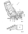
- FIG. 1 shows a vehicle seat 1 or seat 1 according to the invention with a backrest part 2 and a seat part 3, wherein the seat part 3 is connected to a seat base 4 via a front first attachment 20, a rear second attachment 40 and a diagonal attachment 30.
- the seat 1 according to the invention is provided in particular largely symmetrical with respect to its longitudinal axis, so that in an advantageous embodiment of the seat 1 both the front first attachment 20 and the second attachment 40 and the diagonal attachment 30 both on the left side and on the right side of Seat 1 are provided.
- the following is spoken without differentiation of the two sides of the seat 1 of the fasteners 20, 30 and 40 in the singular, but in each case both sides of a respective attachment 20, 30 and 40 are meant.
- FIG. 1a schematically illustrated the controller 10, which is connected to a triggering means 21, a first monitoring means 31, a first actuator 32, a second monitoring means 41, a second actuator 42 and an actuating means 43.
- the actuators 32, 42 of the second attachment 40 and the diagonal attachment 30 depending on the states of the triggering means 21 and the monitoring means 31, 41 and the actuating means 43, that is, in particular, the existing locking and / or unlocking state of Seat, controlled.
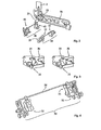
- FIG. 2 are various components of the seat according to the invention in an enlarged view, which is enlarged in size, shown.
- the seat part 3 not fully shown, only a side frame 3b is shown, on which the triggering means 21 can be seen.
- the second attachment 40 and the diagonal attachment 30 are shown with their individual parts.
- the second attachment 40 includes the second actuator 42 and the second Monitoring means 41.
- the diagonal fastening 30 comprises the first actuator 32 and the first monitoring means 31.
- an operating part 23 connected to the backrest part 2, which is moved by a movement of the backrest part 2 and actuates the release means 21 when the backrest part 2 is folded forwards.
- FIG. 3 a section of the side part 3b of the seat part 3 is shown with attached release means 21, wherein in a left part of the FIG. 3 the depending on the position of the backrest or the backrest part 2 moving actuating member 23 cooperates with the release means 21 so that the release means 21 signals a Nachvorneklappen the backrest part 2 in its folded position.
- the actuating member 23 is provided corresponding to the normal position of the backrest part 2, so that the actuating member 23 does not cooperate with the triggering means 21 and signals the folding position of the backrest part 2.
- the diagonal mounting 30 is shown with its first actuator 32, its first monitoring means 31 and an adjusting bracket 34, on which the first actuator 32 acts.
- the first actuator 32 acts on the adjusting yoke 34 of the diagonal fastening 30, the diagonal fastening 30 is released and, according to the invention, can be displaced in particular longitudinally.
- the second attachment 40 is shown, the second attachment 40 comprising the second actuator 42, the second monitoring means 41 and also an adjustment bracket 44, on which - analogous to the diagonal attachment 30 - the second actuator 42 acts.
- the second attachment 40 is released and in particular the seat part 3 relative to the seat base 4 release, so that the seat 1 and the backrest part 2 together with the seat part 3 to the front first attachment 20 around, or around a rotation axis in the region of the front first attachment 20 is rotatably provided.
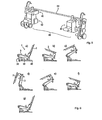
- FIG. 6a to FIG. 6g a sequence of positions of the seat 1 according to the invention is shown to the adjustment of the seat 1 from its normal position in to illustrate his boarding position and back to his normal position.
- the description of the various components of the seat in each case of these sub-figures has been omitted for the sake of simplicity.
- FIG. 6a the seat 1 is shown in its normal position.
- the seat 1 is in FIG. 6b shown with backrest folded backrest part 2.
- the release means 21 is activated, so that the second actuator 42 can provide a release of the seat part 3 in the region of the second attachment 40, which in FIG. 6c is shown.
- FIG. 6d the Einsteigeposition of the seat 1 is shown.
- FIG. 6e the movement of the seat 1 or its backrest part 2 and its seat part 3 is shown back to the normal position, wherein in FIG. 6f a latching of the second attachment 40 takes place, so that the seat part 3 is in turn firmly connected to the seat base 4.
- FIG. 6g the seat 1 is shown in its normal position.
- FIG. 7a to Figure 7g a sequence of positions of the seat 1 according to the invention is shown to illustrate the adjustment of the seat 1 from its normal position to its lowered position and back to its normal position.
- the description of the various components of the seat in each case of these sub-figures has been omitted for the sake of simplicity.
- the seat 1 is shown in its normal position.
- a user by means of the control means 10 connected to the actuating means 43, which, however, in the figures - except schematically in FIG. 1a - Not shown, can initiate the setting of the sinking position.
- the user actuates the actuating means 43, such as a button, touch screen or the like, whereby the controller 10 is signaled that the user intends to adjust the seat 1 in the retractable position.
- the actuating means 43 can therefore be distinguished between the user's request of the adjustment of the seat in the Einsteigeposition and in the sinking position.
- the seat 1 is in FIG. 7b shown with backrest folded backrest part 2.
- the triggering means 21 is activated, so that - because of the previous operation of the actuating means 43 - the first actuator 32 can allow a longitudinal displacement of the diagonal fastening 30, their beginning in FIG. 7c is shown and their complete shift in FIG. 7d is shown.
- FIG. 1 shows a first sequence of positions of a seat to illustrate the adjustment of the seat from the lowered position to an unauthorized position which abuses the large adjustment possibilities of a seat.
- the diagonal fastening 30 is adjusted longitudinally displaced. If, in this situation, the backrest part 2 erected (see. FIG. 8b ) is - with the triggering means 21 is turned off - and subsequently set back into its folding position (see. FIG. 8c ) - the triggering means 21 is actuated again by the actuating member 23 and it is initiated by the controller 10, a release or a solution of the second attachment 40 -, it is possible that by the solution of the second attachment 40 (see.
- FIG. 8d Nachvorneklappen of the seat 1 about a lying in the region of the first attachment 20 axis of rotation despite the course in the retracted position not locked diagonal attachment 30 is conceivable.
- Such misuse of the adjustment options is prevented according to the invention in that the first monitoring means 31 are attached to the diagonal attachment 30, which are actuated by the solution of the diagonal attachment 30 in the retractable position and when actuated, a solution of the second attachment, ie a control of the second actuator 42, prevent.
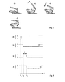
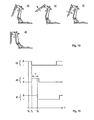
- FIG. 9 is that in FIG. 8 illustrated monitoring principle to prevent the abuse shown in a seat 1 according to the invention again illustrated by a logic diagram.
- four lines are given which represent states of various components of the seat 1 according to the invention. Each line represents the time course t of the state of the respective component. The designation "0" means that the corresponding component is inactive or not actuated.
- the first line relates to the actuating means 43, the second line relates to the triggering means 21, the third line relates to the first actuator 32 and the fourth line relates to the first monitoring means 31.
- the actuating means 43 is activated by a user operation.
- the backrest part 2 is set in its folding position.
- the triggering means 21 When the folding position is reached, the triggering means 21 is thereby activated (by means of the actuating part 23), which is the case at the second time t2.
- the controller 10 activates the first actuator 32 during a predetermined time interval T of, for example, 500 ms in order to enable the sinking position to be reached.
- T a predetermined time interval
- the first monitoring means 31 When the first actuator 32 has released the adjustment yoke 34 of the diagonal attachment 30, the first monitoring means 31 is activated at the third time t3.
- the controller 10 is now provided according to the invention such that a subsequent activation of the second actuator 42 is omitted as long as the first monitoring means signals an unlocking of the diagonal attachment 30 and this also for the case that the triggering means 21 - possibly by in the FIG. 8 shown adjustment operations of the backrest part 2 - is actuated again and could in principle cause a release of the second attachment 40 by activation of the second actuator 42.
- FIG. 10a to FIG. 10d a second sequence of positions of a seat is shown to illustrate the adjustment of the seat from the boarding position to an unauthorized and the large adjustment of a seat abusing position.
- the second attachment 40 is provided loosely, that is, the backrest part 2 and the seat part 3 can be folded around an axis of rotation in the region of the first attachment 20 forward. If, in this situation, the backrest part 2 erected (see. FIG. 10b ) is - with the triggering means 21 is turned off - and subsequently set back into its folding position (see. FIG.
- FIG. 11 is that in FIG. 10 illustrated monitoring principle to prevent the abuse shown in a seat 1 according to the invention again illustrated by a logic diagram.
- three lines are given, representing the states of various components of the seat 1 according to the invention. Each line represents the time course t of the state of the respective component. The designation "0" means that the corresponding component is inactive or not actuated.
- the first line relates to the triggering means 21, the second line relates to the second actuator 42 and the third line relates to the second monitoring means 41.
- the backrest is adjusted by a mechanical unlocking of the locking of the backrest part 2. As a result, the backrest part 2 is set in its folding position.
- the triggering means 21 is thereby activated (by means of the actuating part 23), which is the case at the fifth time t5.
- the controller 10 activates the second actuator 42 during a predetermined time interval T of, for example, 500 ms in order to enable the reaching in position to be reached.
- the second monitoring means 41 is activated at the same time t6.
- the control is 10 according to the invention provided such that a subsequent activation of the first actuator 32 is omitted as long as the second monitoring means 41 signals an unlocking of the second attachment 40 and this also for the case that the triggering means 21 - possibly by in the FIG. 10 illustrated adjusting operations of the Lehnenteils 2 - is actuated again and in principle could cause a release of the diagonal fastening 30 by activation of the first actuator 32.
- the release means 21 and the monitoring means 31, 41 are inventively provided in particular as a contact switch or as a micro-switch, which are switched mechanically by the movement of certain components.
- Representative of these components is the actuating member 23 for actuating the triggering means 21.
- a part of the tripping or monitoring means 21, 31, 41 perform a monitoring of the condition, while others carry out a monitoring of changes.
- the triggering means 21 responds to "flanks" or is evaluated by the control device 10 on "flanks" of its signal, while the first and second monitoring means 31, 41 only react to detected states, i. be evaluated by the controller 10 exclusively for instantaneous signals. From the latter there is the advantage that the evaluation of the monitoring means 31, 41 is independent of the movement history of the seat and thus an increased robustness of the system is given, for example, during power outages.
Landscapes
- Engineering & Computer Science (AREA)
- Aviation & Aerospace Engineering (AREA)
- Transportation (AREA)
- Mechanical Engineering (AREA)
- Seats For Vehicles (AREA)
- Chemical And Physical Treatments For Wood And The Like (AREA)
Abstract
Description
Die Erfindung betrifft einen Sitz, insbesondere einen Fahrzeugsitz, nach dem Oberbegriff des Anspruchs 1. Insbesondere für Kraftfahrzeuge ist es zunehmend erforderlich, Komponenten bereitzustellen, die den Komfortbedürfnissen ihrer Benutzer in immer größerem Maße gerecht werden. Bei Sitzen für Kraftfahrzeuge wirkt sich dies dadurch aus, dass beispielsweise als Einstiegshilfe in ein Kraftfahrzeug für Benutzer des Kraftfahrzeuges, die auf der Rücksitzbank eines Kraftfahrzeuges Platz nehmen möchten, die Lehne eines vor der Rücksitzbank befindlichen Sitzes nach vorne, d.h. von der Rücksitzbank weg, geklappt werden soll. Für insbesondere für Familien besonders geeignete Fahrzeuge, besonders sogenannte "Vans" oder "Großraumlimousinen", ist es vorteilhaft, dass weitere Funktionsmöglichkeiten bzw. Positionen von Fahrzeugsitzen möglich sind, beispielsweise kann die Lehne eines solchen Sitzes derart nach vorn geklappt werden, dass die Rückseite der Lehne als Tisch verwendbar ist.The invention relates to a seat, in particular a vehicle seat, according to the preamble of
Es ist allgemein bekannt Fahrzeugsitze zu verwenden, die insbesondere in Fahrzeugen, die keine separaten Türen als Zugang für eine Rücksitzbank aufweisen, eine Lehne derart aufweisen, dass zum bequemeren Einstieg von Passagieren auf die Rücksitzbank die Rückenlehne des Fahrzeugsitzes nach vorne geklappt wird. Hierzu wird in der Regel manuell eine mechanische Entriegelungsvorrichtung betätigt, so dass die Lehne, die in ihrer Normalposition in einem bestimmten, einstellbaren Neigungswinkel zur Sitzfläche arretiert vorgesehen ist, nach vorne geklappt werden kann. Hierbei ist es nachteilig, dass der gesamte Sitzunterbau in der gleichen Position verharrt, d.h. an der gleichen Stelle verbleibt, und damit beim Einstieg der Passagiere weiterhin hinderlich ist. Solche Fahrzeugsitze sind beispielsweise aus den Druckschriften
Der Erfindung liegt daher die Aufgabe zugrunde, einen Sitz, insbesondere einen Fahrzeugsitz zu schaffen, der über ein Höchstmaß an Variationsmöglichkeiten hinsichtlich seiner für unterschiedliche Benutzungssituationen vorgesehenen Einstellpositionen verfügt. Darüber hinaus ist erfindungsgemäß vorgesehen, einen Missbrauch der Einstellmöglichkeiten bzw. eine nicht vorgesehene Kombination von Einstellmöglichkeiten zu verhindern.The invention is therefore based on the object to provide a seat, in particular a vehicle seat, which has a maximum of possible variations in terms of its intended for different situations of use adjustment positions. In addition, the invention provides a Abuse of the setting options or to prevent an unintended combination of setting options.
Diese Aufgabe wird erfindungsgemäß durch einen Sitz gemäß Anspruch 1 gelöst. Hierdurch ergibt sich ein Höchstmaß an Einstellmöglichkeiten, die zu einer Vergrößerung des Bedienungskomforts bei der Benutzung des Sitzes und des Kraftfahrzeuges führt. Weiterhin ist von Vorteil, dass Auslösemittel vorgesehen sind, wobei die Auslösemittel bei in ihrer Klapposition befindlicher Lehne eine Lösung entweder der Diagonalbefestigung oder der zweiten Befestigung lediglich während eines vorgegebenen Zeitintervalls bewirken. Dadurch sind Missbräuche einer Benutzung des Sitzes weiterhin eingeschränkt.This object is achieved by a seat according to
In einer bevorzugten Ausführungsform der Erfindung ist in der Einsteigeposition das Sitzteil im Bereich der zweiten Befestigung vom Sitzunterbau getrennt vorgesehen und/oder es ist in der Versenkposition die Diagonalbefestigung gegenüber ihrer Einstellung in der Normalposition längsverschoben vorgesehen. Hierdurch ergibt sich insbesondere der Vorteil, dass der Ort, an dem sich das Sitzteil in seiner Normaposition befindet, für eine Benutzung durch einen Insassen freigebbar ist. Weiterhin ergibt sich dadurch der Vorteil, dass der Sitz versenkbar vorgesehen ist, d. h. dass selbst bei einem relativ dicken Lehnenteil des Sitzes eine Benutzung der Lehne als Tisch möglich ist, ohne dass ein solcher "Tisch" für eine Benutzung in dem Fahrzeug untauglich, weil beispielsweise zu hoch angeordnet, wäre.In a preferred embodiment of the invention, in the entry position, the seat part is provided separately from the seat base in the region of the second attachment and / or the diagonal attachment is longitudinally displaced in the lowered position relative to its setting in the normal position. This results in particular the advantage that the place where the seat part is in its normal position, is releasable for use by an occupant. Furthermore, this results in the advantage that the seat is provided retractable, d. H. that even with a relatively thick backrest part of the seat, use of the backrest as a table is possible without such a "table" unfit for use in the vehicle, because, for example, arranged too high.
Weiterhin ist es vorteilhaft, dass zur Trennung des Sitzteiles im Bereich der zweiten Befestigung eine zweiter Aktuator vorgesehen ist und/oder dass zur Längsverschiebung der Diagonalbefestigung ein erster Aktuator vorgesehen ist, wobei der erste und/oder der zweite Aktuator insbesondere als elektromotorische Aktuatoren vorgesehen sind. In vorteilhafter Weise wird dadurch bewirkt, dass die Ermöglichung der verschiedenen Einstellmöglichkeiten des Sitzes automatisiert bzw. gesteuert vorgenommen werden kann und somit eine direkte Entriegelung durch einen Benutzer entfällt, was zum einen die Benutzung erleichtert, weil beispielsweise nicht an unzugänglichen Stellen des Sitzes hantiert werden muss, und zum anderen die Konstruktion des Sitzes vereinfacht und damit verbilligt, weil keine unhandlichen und gewichtsverursachenden Griffe, Hebel oder sonstige Betätigungsvorrichtungen vorgesehen sein müssen.Furthermore, it is advantageous that a second actuator is provided for separating the seat part in the region of the second fastening and / or that a first actuator is provided for longitudinal displacement of the diagonal fastening, wherein the first and / or the second actuator are provided in particular as electromotive actuators. Advantageously, this causes the possibility of the various adjustment options of the seat can be made automated or controlled and thus eliminates a direct release by a user, which on the one hand facilitates the use, for example, does not have to be handled in inaccessible places of the seat , and on the other hand simplified the construction of the seat and thus cheaper, because no unwieldy and weight-causing handles, levers or other actuators must be provided.
Weiterhin ist von Vorteil, dass erste Überwachungsmittel vorgesehen sind, wobei die ersten Überwachungsmittel eine Verhinderung der Lösung der Diagonalbefestigung in der Einsteigeposition bewirken und/oder das zweite Überwachungsmittel vorgesehen sind, aber wobei die zweiten Überwachungsmittel eine Verhinderung der Lösung der zweiten Befestigung in der Versenkposition bewirken. Dadurch ist es erfindunsgemäß vorteilhaft möglich, dass ein Mißbrauch der verschiedenen Verstellmöglichkeiten des Sitzes durch eine unsachgemäße Benutzung weitgehend ausgeschlossen ist.Furthermore, it is advantageous that first monitoring means are provided, wherein the first monitoring means cause a prevention of the solution of the diagonal fastening in the boarding position and / or the second monitoring means are provided, but wherein the second monitoring means cause a prevention of the solution of the second attachment in the sinking position , As a result, it is advantageously possible according to the invention that misuse of the various adjustment possibilities of the seat due to improper use is largely precluded.
Weiterhin ist von Vorteil, dass die ersten Überwachungsmittel und/oder die zweiten Überwachungsmittel und/oder die Auslösemittel als Mikroschalter vorgesehen sind. Hierdurch ist es in besonders einfacher und kostengünstiger Weise möglich, die erfindungsgemäßen Überwachungsmittel an einem Sitz bereitzustellen.Furthermore, it is advantageous that the first monitoring means and / or the second monitoring means and / or the triggering means are provided as micro-switches. This makes it possible in a particularly simple and cost-effective manner to provide the monitoring means according to the invention on a seat.
Weiterhin ist von Vorteil, dass der Sitz eine Steuerungseinrichtung zur Steuerung der Lösung der Befestigungen in Abhängigkeit der von dem Sitz eingenommenen Position aufweist. Durch die Realisierung der Steuerungseinrichtung, beispielsweise als programmierbare Steuerungseinrichtung, ist es erfindungsgemäß in einfacher Weise möglich, einen Mißbrauch der verschiedenen Verstellmöglichkeiten des erfindungsgemäßen Sitzes auszuschließen.Furthermore, it is advantageous that the seat has a control device for controlling the solution of the fasteners as a function of the position assumed by the seat. By realizing the control device, for example as a programmable control device, it is possible according to the invention in a simple manner to preclude misuse of the various adjustment possibilities of the seat according to the invention.
Ein weiterer Gegenstand der vorliegenden Erfindung ist ein Verfahren, bei dem ein erfindungsgemäßer Sitz derart gesteuert wird, dass er über ein Höchstmaß an vomAnother object of the present invention is a method in which a seat according to the invention is controlled in such a way that it reaches a maximum of
Benutzer wählbaren Einstellmöglichkeiten verfügt und gleichzeitig ein Mißbrauch dieser erhöhten Funktionalität in starkem Maße eingeschränkt ist.User has selectable setting options and at the same time a misuse of this increased functionality is severely limited.
Die Erfindung wird nachfolgend anhand von in der Zeichnung dargestellten Ausführungsbeispielen näher erläutert.
-
Figur 1 - zeigt einen erfindungsgemäßen Sitz mit einem Lehnenteil und einem Sitzteil.
- Figur 1 a
- ist schematisch eine Steuerung.
-
Figur 2 - zeigt verschiedene Komponenten des erfindungsgemäßen Sitzes in einer vergrößerten Darstellung.
-
Figur 3 - zeigt einen Ausschnitt eines Seitenteils des
Sitzteils 3 mit angebrachten Auslösemitteln. -
Figur 4 - zeigt die Diagonalbefestigung.
- Figur 5
- zeigt die zweite Befestigung.
- Figur 6a bis 6g
- zeigen eine Abfolge von Positionen des erfindungsgemäßen Sitzes mit Bezug auf die Einsteigeposition.
- Figur 7a bis 7g
- zeigen eine Abfolge von Positionen des erfindungsgemäßen Sitzes mit Bezug auf die Versenkposition.
- Figur 8a bis 8d
- zeigt eine erste Abfolge von teilweise missbräuchlichen Positionen eines Sitzes.
- Figur 9
- zeigt das in
Figur 8 dargestellte Überwachungsprinzip anhand eines Logikdiagramms. - Figur 10a bis 10d
- zeigt eine zweite Abfolge von teilweise missbräuchlichen Positionen eines Sitzes.
- Figur 11
- zeigt das in
Figur 10
- FIG. 1
- shows a seat according to the invention with a backrest part and a seat part.
- FIG. 1 a
- is schematically a controller.
- FIG. 2
- shows various components of the seat according to the invention in an enlarged view.
- FIG. 3
- shows a section of a side part of the
seat part 3 with attached release means. - FIG. 4
- shows the diagonal fastening.
- FIG. 5
- shows the second attachment.
- FIGS. 6a to 6g
- show a sequence of positions of the seat according to the invention with respect to the boarding position.
- FIGS. 7a to 7g
- show a sequence of positions of the seat according to the invention with respect to the sinking position.
- Figure 8a to 8d
- shows a first sequence of partially abusive positions of a seat.
- FIG. 9
- shows that in
FIG. 8 illustrated monitoring principle using a logic diagram. - FIGS. 10a to 10d
- shows a second sequence of partially abusive positions of a seat.
- FIG. 11
- shows that in
FIG. 10 illustrated monitoring principle using a logic diagram.
In
In
In
In
In
In
In
In
In
In
In
Das Auslösemittel 21 und die Überwachungsmittel 31, 41 sind erfindungsgemäß insbesondere als Kontaktschalter bzw. als Mikroschalter vorgesehen, die mechanisch durch die Bewegung von bestimmten Komponenten geschaltet werden. Stellvertretend für diese Komponenten steht das Betätigungsteil 23 zur Betätigung des Auslösemittels 21. Hierbei kann es erfindungsgemäß insbesondere vorgesehen sein, dass ein Teil der Auslöse- bzw. Überwachungsmittel 21, 31, 41 eine Überwachung des Zustandes durchführen, während andere eine Überwachung von Änderungen durchführen. Beispielsweise ist es erfindungsgemäß vorgesehen, dass das Auslösemittel 21 auf "Flanken" reagiert bzw. von der Steuerungseinrichtung 10 auf "Flanken" seines Signals hin ausgewertet wird, währenddem das erste und zweite Überwachungsmittel 31, 41 lediglich auf detektierte bzw. eingenommene Zustände reagiert, d.h. von der Steuerungseinrichtung 10 ausschließlich auf momentane Signale hin ausgewertet werden. Aus dem letzteren ergibt sich der Vorteil, dass die Auswertung der Überwachungsmittel 31, 41 unabhängig von der Bewegungshistorie des Sitzes ist und somit eine erhöhte Robustheit des Systems beispielsweise bei Stromausfällen gegeben ist.The release means 21 and the monitoring means 31, 41 are inventively provided in particular as a contact switch or as a micro-switch, which are switched mechanically by the movement of certain components. Representative of these components is the actuating
Die Unterscheidung zwischen der Einstellung der Versenkposition oder der Einsteigeposition ausgehend von der Normalposition kann auch dadurch geschehen, dass ein nicht dargestellter Wählschalter vorgesehen ist, dessen eine Einstellmöglichkeit für die Einstellung der Versenkposition steht und dessen andere Einstellmöglichkeit für die Einstellung der Einsteigeposition steht. Dadurch kann ein Benutzer des erfindungsgemäßen Sitzes diese beiden Position eindeutig und separat einstellen bzw. deren Einstellung einleiten.The distinction between the setting of the sinking position or the Einsteigeposition starting from the normal position can also be done by an unillustrated selector switch is provided, which is an adjustment for setting the retractable position and whose other adjustment for setting the boarding position. As a result, a user of the seat according to the invention can set these two positions clearly and separately or initiate their adjustment.
- 11
- SitzSeat
- 22
- Lehnenteilback part
- 33
- Sitzteilseat part
- 3b3b
- Seitenteil des SitzteilsSide part of the seat part
- 44
- Sitzunterbauseat substructure
- 1010
- Steuerungcontrol
- 2020
- erste Befestigungfirst attachment
- 2121
- Auslösemittelrelease means
- 3030
- DiagonalbefestigungDiagonal fixing
- 3131
- erstes Überwachungsmittelfirst monitoring means
- 3232
- erster Aktuatorfirst actuator
- 3434
- Verstellbügel der DiagonalbefestigungAdjusting the diagonal fastening
- 4040
- zweite Befestigungsecond attachment
- 4141
- zweites Überwachungsmittelsecond monitoring means
- 4242
- zweiter Aktuatorsecond actuator
- 4343
- Betätigungsmittelactuating means
- 4444
- Verstellbügel der zweiten BefestigungAdjustment bar of the second attachment
- tt
- zeitlicher Verlauftime course
- t1t1
- erster Zeitpunktfirst time
- t2t2
- zweiter Zeitpunktsecond time
- t3t3
- dritter Zeitpunktthird time
- t4t4
- vierter Zeitpunktfourth time
- t5t5
- fünfter Zeitpunktfifth time
- t6t6
- sechter Zeitpunkttime of day
- TT
- Zeitintervalltime interval
Claims (6)
- Seat (1), in particular a motor vehicle seat, with a backrest part (2) and with a seat part (3), the backrest part (2) being provided in a manner such that it can be folded relative to the seat part (3) from a normal position into a folded position and vice-versa, the seat (1) having a lower seat structure (4), the seat part (3) being provided in a manner such that it is movable relative to the lower seat structure (4), wherein, in order to fasten the seat part (3) to the lower seat structure (4), at least one front first fastening (20), one rear second fastening (40) and one diagonal fastening (30) are provided, the seat (1) being provided in a manner such that it can be adjusted at least into an entry position and into a lowered position apart from into a normal position, the second fastening (40) being provided in a manner such that it is released in the entry position, and the diagonal fastening (30) being provided in a manner such that it is released in the lowered position, characterized in that triggering means (21) are provided, the triggering means (21), with the backrest (2) in its folded position, leading either to the diagonal fastening (30) or the second fastening (40) being released only during a predetermined time interval (T).
- Seat (1) according to Claim 1, characterized in that in the entry position the seat part (3) is provided in a manner such that it is separated in the region of the second fastening (40) from the lower seat structure (4) and/or in that in the lowered position the diagonal fastening (30) is provided in a manner such that it is displaced longitudinally in relation to its setting in the normal position.
- Seat (1) according to one of the preceding claims, characterized in that, in order to separate the seat part (3) in the region of the second fastening (40), a second actuator (42) is provided, and/or in that, in order to longitudinally displace the diagonal fastening (30), a first actuator (32) is provided, the first and/or second actuator(s) (32, 42) being provided in particular as electric motor actuators.
- Seat (1) according to one of the preceding claims, characterized in that first monitoring means (31) are provided, the first monitoring means leading to the diagonal fastening (30) being prevented from being released in the entry position, and/or in that second monitoring means (41) are provided, the second monitoring means (41) leading to the second fastening (40) being prevented from being released in the lowered position.
- Seat (1) according to Claim 4, characterized in that the first monitoring means (31) and/or the second monitoring means (41) and/or the triggering means (21) are provided as microswitches.
- Seat (1) according to one of the preceding claims, characterized in that the seat (1) has a control device (10) for controlling the release of the fastenings (20, 30, 40) as a function of the existing locking and/or unlocking state.
Priority Applications (1)
| Application Number | Priority Date | Filing Date | Title |
|---|---|---|---|
| PL04764898T PL1663703T3 (en) | 2003-09-09 | 2004-09-07 | Seat and method |
Applications Claiming Priority (2)
| Application Number | Priority Date | Filing Date | Title |
|---|---|---|---|
| DE10341375A DE10341375B4 (en) | 2003-09-09 | 2003-09-09 | Seat, in particular motor vehicle seat |
| PCT/EP2004/009955 WO2005025931A1 (en) | 2003-09-09 | 2004-09-07 | Seat and method |
Publications (2)
| Publication Number | Publication Date |
|---|---|
| EP1663703A1 EP1663703A1 (en) | 2006-06-07 |
| EP1663703B1 true EP1663703B1 (en) | 2011-08-10 |
Family
ID=34258495
Family Applications (1)
| Application Number | Title | Priority Date | Filing Date |
|---|---|---|---|
| EP04764898A Expired - Lifetime EP1663703B1 (en) | 2003-09-09 | 2004-09-07 | Seat and method |
Country Status (7)
| Country | Link |
|---|---|
| US (1) | US7802850B2 (en) |
| EP (1) | EP1663703B1 (en) |
| JP (1) | JP4722046B2 (en) |
| AT (1) | ATE519621T1 (en) |
| DE (1) | DE10341375B4 (en) |
| PL (1) | PL1663703T3 (en) |
| WO (1) | WO2005025931A1 (en) |
Families Citing this family (10)
| Publication number | Priority date | Publication date | Assignee | Title |
|---|---|---|---|---|
| US7552972B2 (en) | 2005-06-02 | 2009-06-30 | Lear Corporation | Power assist fold and tumble vehicle seat |
| US7699399B2 (en) * | 2005-08-30 | 2010-04-20 | Aisin Seiki Kabushiki Kaisha | Seat apparatus |
| JP5309746B2 (en) * | 2008-07-15 | 2013-10-09 | トヨタ紡織株式会社 | Vehicle seat |
| JP5751083B2 (en) | 2011-08-11 | 2015-07-22 | トヨタ紡織株式会社 | Vehicle seat |
| DE102011084087B4 (en) | 2011-10-06 | 2020-06-04 | Bayerische Motoren Werke Aktiengesellschaft | Adjustment device for the ergonomic adjustment of a vehicle seat with several adjustable seat components and / or for the ergonomic adjustment of adjustable vehicle components depending on the seat position |
| FR3071447B1 (en) | 2017-09-22 | 2020-05-22 | Faurecia Sieges D'automobile | AUTOMATIC TIPPING SEAT |
| DE102018112926B4 (en) * | 2018-05-30 | 2022-04-14 | Adient Engineering and IP GmbH | vehicle seat |
| US11351891B2 (en) * | 2018-09-27 | 2022-06-07 | Faurecia Sièges d'Automobile | System comprising a vehicle seat with tilting backrest |
| FR3101290B1 (en) * | 2019-09-30 | 2022-12-23 | Faurecia Sieges Dautomobile | vehicle seat |
| CN219270552U (en) * | 2023-02-18 | 2023-06-30 | 顾家家居股份有限公司 | Sofa with backrest folding function |
Family Cites Families (25)
| Publication number | Priority date | Publication date | Assignee | Title |
|---|---|---|---|---|
| JPS57165529A (en) * | 1981-04-04 | 1982-10-12 | Koichi Miura | Construction of strip footing |
| JPS6056648B2 (en) * | 1981-09-01 | 1985-12-11 | マツダ株式会社 | car seat |
| JPS61202941A (en) * | 1985-03-04 | 1986-09-08 | Nippon Soken Inc | Power seat folding controller |
| DE3801294C2 (en) * | 1988-01-19 | 1995-01-19 | Daimler Benz Ag | Folding vehicle seat |
| DE4220661C2 (en) * | 1992-06-24 | 1997-07-31 | Man Nutzfahrzeuge Ag | Foldable travel companion seat in buses |
| CA2111725C (en) * | 1993-12-18 | 1998-10-13 | Wojciech Smuk | Combination reclining and folding mechanism for automotive seat assemblies |
| DE29715345U1 (en) * | 1997-08-27 | 1998-12-24 | Johnson Controls GmbH, 51399 Burscheid | Seat construction, especially for rear seats in motor vehicles |
| US6012755A (en) * | 1997-10-15 | 2000-01-11 | Lear Corporation | Foldable automotive seat |
| BR9911971A (en) * | 1998-07-14 | 2001-03-27 | Magna Interior Sys Inc | Car seat and seat lift mounts |
| US6000742A (en) * | 1999-02-01 | 1999-12-14 | Ford Motor Company | Multi-positional seat mounting apparatus |
| US6024411A (en) * | 1999-03-17 | 2000-02-15 | Daimlerchrysler Corporation | Seat mounted cupholder adapted for seat riser fold and tumble mechanism |
| DE19964143C2 (en) * | 1999-09-11 | 2001-07-12 | Keiper Gmbh & Co | Vehicle seat with package position |
| US6174017B1 (en) * | 1999-11-04 | 2001-01-16 | Daimlerchrysler Corporation | Dumping and articulating seat |
| US6131999A (en) * | 1999-11-22 | 2000-10-17 | Ford Motor Company | Folding vehicle seat assembly |
| US6135555A (en) * | 1999-11-22 | 2000-10-24 | Ford Motor Company | Tumbling vehicle seat assembly |
| US6793285B1 (en) * | 2000-03-13 | 2004-09-21 | Magna Seating Systems Inc. | Safety mechanism for a fold and tumble seat assembly |
| US6590354B2 (en) * | 2000-10-19 | 2003-07-08 | Lear Corporation | Seat adjusting system having motor with integrated sensor and control electronics |
| DE10056024C2 (en) | 2000-11-11 | 2002-10-31 | Bosch Gmbh Robert | Cars with rear seats |
| DE10130813C2 (en) * | 2001-06-26 | 2003-06-05 | Keiper Gmbh & Co Kg | Vehicle seat with floor position |
| DE10136244C1 (en) * | 2001-07-25 | 2002-08-29 | Keiper Gmbh & Co | Vehicle seat, in particular motor vehicle seat |
| DE10139538C1 (en) * | 2001-08-10 | 2003-03-20 | Faurecia Autositze Gmbh & Co | Rear seat for motor vehicles |
| JP3597497B2 (en) * | 2001-10-16 | 2004-12-08 | 本田技研工業株式会社 | Vehicle seat |
| US7118178B2 (en) * | 2002-11-06 | 2006-10-10 | Intier Automotive Inc, | Power folding seat |
| US6857703B2 (en) * | 2002-11-05 | 2005-02-22 | Fisher Dynamics Corporation | Fold, tumble and kneel seat assembly |
| US7959230B2 (en) * | 2003-04-11 | 2011-06-14 | Johnson Controls Technology Company | Seating system for a vehicle |
-
2003
- 2003-09-09 DE DE10341375A patent/DE10341375B4/en not_active Expired - Fee Related
-
2004
- 2004-09-07 US US10/571,185 patent/US7802850B2/en not_active Expired - Fee Related
- 2004-09-07 AT AT04764898T patent/ATE519621T1/en active
- 2004-09-07 WO PCT/EP2004/009955 patent/WO2005025931A1/en not_active Ceased
- 2004-09-07 PL PL04764898T patent/PL1663703T3/en unknown
- 2004-09-07 JP JP2006525737A patent/JP4722046B2/en not_active Expired - Fee Related
- 2004-09-07 EP EP04764898A patent/EP1663703B1/en not_active Expired - Lifetime
Also Published As
| Publication number | Publication date |
|---|---|
| ATE519621T1 (en) | 2011-08-15 |
| US7802850B2 (en) | 2010-09-28 |
| PL1663703T3 (en) | 2012-01-31 |
| EP1663703A1 (en) | 2006-06-07 |
| DE10341375A1 (en) | 2005-04-07 |
| JP4722046B2 (en) | 2011-07-13 |
| DE10341375B4 (en) | 2005-09-29 |
| US20070236068A1 (en) | 2007-10-11 |
| WO2005025931A1 (en) | 2005-03-24 |
| JP2007504990A (en) | 2007-03-08 |
Similar Documents
| Publication | Publication Date | Title |
|---|---|---|
| EP0826855B1 (en) | Lock, specially for vehicle doors or the like | |
| DE102005051298B4 (en) | Seat arrangement for a vehicle | |
| EP1997997A2 (en) | Method for powered adjustment of a motor vehicle door | |
| EP1078807B1 (en) | Electrical drive device for a front seat of a motor vehicle | |
| EP1178897B1 (en) | Control device for controlling adjustment motors for adjusting different parts of a seat | |
| EP1663703B1 (en) | Seat and method | |
| DE102016207524A1 (en) | Adjustment device for a vehicle seat and control method | |
| DE19631454C2 (en) | Vehicle seat with a seat plate and a backrest | |
| DE102019001066A1 (en) | Seat system for an interior of a motor vehicle | |
| DE102013224282A1 (en) | Automatic method of a movable by foreign power seat of a passenger car with continuous operation of the outside door handle | |
| DE19630223C2 (en) | Adjustment device for a front seat of a motor vehicle | |
| DE102004033222B4 (en) | seat adjustment | |
| DE19951120C2 (en) | Device and method for facilitating getting in and / or out of a rear seat of a four-door motor vehicle | |
| EP0257538B2 (en) | Switching arrangement in motor vehicles | |
| DE102004061141A1 (en) | Door tightening knob e.g. for motor vehicle is mounted on door element by means of adjustment device relative to door element against opening angle of door element | |
| DE102013000164A1 (en) | Vehicle seat for passenger car, has control element that is pivoted about pivot axis of release lever without actuation of release lever, to unlock locking latch | |
| WO2006092210A2 (en) | Motor vehicle | |
| DE102016114884A1 (en) | Motor vehicle interior arrangement with an actuating device for a locking system | |
| DE102017101075B4 (en) | Method for moving a motor vehicle seat with an easy-entry function | |
| DE3447039C2 (en) | Central locking for motor vehicles | |
| DE102004048821B4 (en) | Device and method for adjusting a vehicle component | |
| EP1681198B1 (en) | Device for allowing access to a closed space inside an automotive vehicle | |
| DE69600339T2 (en) | Device for controlling an electrically operated sunroof device for a motor vehicle | |
| DE19711369B4 (en) | Control device for a vehicle with remote control of the passenger side | |
| DE102004010592A1 (en) | Adjustable driver's seat for road vehicle has electric motors connected to buttons or sensors on steering wheel and electronic control system with menu may be installed in dashboard |
Legal Events
| Date | Code | Title | Description |
|---|---|---|---|
| PUAI | Public reference made under article 153(3) epc to a published international application that has entered the european phase |
Free format text: ORIGINAL CODE: 0009012 |
|
| 17P | Request for examination filed |
Effective date: 20060321 |
|
| AK | Designated contracting states |
Kind code of ref document: A1 Designated state(s): AT BE BG CH CY CZ DE DK EE ES FI FR GB GR HU IE IT LI LU MC NL PL PT RO SE SI SK TR |
|
| DAX | Request for extension of the european patent (deleted) | ||
| 17Q | First examination report despatched |
Effective date: 20081110 |
|
| GRAP | Despatch of communication of intention to grant a patent |
Free format text: ORIGINAL CODE: EPIDOSNIGR1 |
|
| GRAS | Grant fee paid |
Free format text: ORIGINAL CODE: EPIDOSNIGR3 |
|
| GRAA | (expected) grant |
Free format text: ORIGINAL CODE: 0009210 |
|
| AK | Designated contracting states |
Kind code of ref document: B1 Designated state(s): AT BE BG CH CY CZ DE DK EE ES FI FR GB GR HU IE IT LI LU MC NL PL PT RO SE SI SK TR |
|
| REG | Reference to a national code |
Ref country code: GB Ref legal event code: FG4D Free format text: NOT ENGLISH |
|
| REG | Reference to a national code |
Ref country code: CH Ref legal event code: EP |
|
| REG | Reference to a national code |
Ref country code: DE Ref legal event code: R081 Ref document number: 502004012784 Country of ref document: DE Owner name: ADIENT LUXEMBOURG HOLDING S.A.R.L., LU Free format text: FORMER OWNER: JOHNSON CONTROLS GMBH, 51399 BURSCHEID, DE Ref country code: DE Ref legal event code: R081 Ref document number: 502004012784 Country of ref document: DE Owner name: ADIENT LUXEMBOURG HOLDING S.A R.L., LU Free format text: FORMER OWNER: JOHNSON CONTROLS GMBH, 51399 BURSCHEID, DE |
|
| REG | Reference to a national code |
Ref country code: IE Ref legal event code: FG4D Free format text: LANGUAGE OF EP DOCUMENT: GERMAN |
|
| REG | Reference to a national code |
Ref country code: DE Ref legal event code: R096 Ref document number: 502004012784 Country of ref document: DE Effective date: 20111006 |
|
| REG | Reference to a national code |
Ref country code: NL Ref legal event code: VDEP Effective date: 20110810 |
|
| REG | Reference to a national code |
Ref country code: SK Ref legal event code: T3 Ref document number: E 10366 Country of ref document: SK |
|
| PG25 | Lapsed in a contracting state [announced via postgrant information from national office to epo] |
Ref country code: NL Free format text: LAPSE BECAUSE OF FAILURE TO SUBMIT A TRANSLATION OF THE DESCRIPTION OR TO PAY THE FEE WITHIN THE PRESCRIBED TIME-LIMIT Effective date: 20110810 Ref country code: SE Free format text: LAPSE BECAUSE OF FAILURE TO SUBMIT A TRANSLATION OF THE DESCRIPTION OR TO PAY THE FEE WITHIN THE PRESCRIBED TIME-LIMIT Effective date: 20110810 Ref country code: FI Free format text: LAPSE BECAUSE OF FAILURE TO SUBMIT A TRANSLATION OF THE DESCRIPTION OR TO PAY THE FEE WITHIN THE PRESCRIBED TIME-LIMIT Effective date: 20110810 Ref country code: PT Free format text: LAPSE BECAUSE OF FAILURE TO SUBMIT A TRANSLATION OF THE DESCRIPTION OR TO PAY THE FEE WITHIN THE PRESCRIBED TIME-LIMIT Effective date: 20111212 |
|
| REG | Reference to a national code |
Ref country code: PL Ref legal event code: T3 |
|
| PG25 | Lapsed in a contracting state [announced via postgrant information from national office to epo] |
Ref country code: SI Free format text: LAPSE BECAUSE OF FAILURE TO SUBMIT A TRANSLATION OF THE DESCRIPTION OR TO PAY THE FEE WITHIN THE PRESCRIBED TIME-LIMIT Effective date: 20110810 Ref country code: CY Free format text: LAPSE BECAUSE OF FAILURE TO SUBMIT A TRANSLATION OF THE DESCRIPTION OR TO PAY THE FEE WITHIN THE PRESCRIBED TIME-LIMIT Effective date: 20110810 Ref country code: GR Free format text: LAPSE BECAUSE OF FAILURE TO SUBMIT A TRANSLATION OF THE DESCRIPTION OR TO PAY THE FEE WITHIN THE PRESCRIBED TIME-LIMIT Effective date: 20111111 |
|
| REG | Reference to a national code |
Ref country code: IE Ref legal event code: FD4D |
|
| BERE | Be: lapsed |
Owner name: JOHNSON CONTROLS G.M.B.H. Effective date: 20110930 |
|
| PG25 | Lapsed in a contracting state [announced via postgrant information from national office to epo] |
Ref country code: MC Free format text: LAPSE BECAUSE OF NON-PAYMENT OF DUE FEES Effective date: 20110930 Ref country code: IE Free format text: LAPSE BECAUSE OF FAILURE TO SUBMIT A TRANSLATION OF THE DESCRIPTION OR TO PAY THE FEE WITHIN THE PRESCRIBED TIME-LIMIT Effective date: 20110810 |
|
| REG | Reference to a national code |
Ref country code: CH Ref legal event code: PL |
|
| PG25 | Lapsed in a contracting state [announced via postgrant information from national office to epo] |
Ref country code: EE Free format text: LAPSE BECAUSE OF FAILURE TO SUBMIT A TRANSLATION OF THE DESCRIPTION OR TO PAY THE FEE WITHIN THE PRESCRIBED TIME-LIMIT Effective date: 20110810 Ref country code: RO Free format text: LAPSE BECAUSE OF FAILURE TO SUBMIT A TRANSLATION OF THE DESCRIPTION OR TO PAY THE FEE WITHIN THE PRESCRIBED TIME-LIMIT Effective date: 20110810 Ref country code: IT Free format text: LAPSE BECAUSE OF FAILURE TO SUBMIT A TRANSLATION OF THE DESCRIPTION OR TO PAY THE FEE WITHIN THE PRESCRIBED TIME-LIMIT Effective date: 20110810 |
|
| PLBE | No opposition filed within time limit |
Free format text: ORIGINAL CODE: 0009261 |
|
| STAA | Information on the status of an ep patent application or granted ep patent |
Free format text: STATUS: NO OPPOSITION FILED WITHIN TIME LIMIT |
|
| PG25 | Lapsed in a contracting state [announced via postgrant information from national office to epo] |
Ref country code: BE Free format text: LAPSE BECAUSE OF NON-PAYMENT OF DUE FEES Effective date: 20110930 Ref country code: DK Free format text: LAPSE BECAUSE OF FAILURE TO SUBMIT A TRANSLATION OF THE DESCRIPTION OR TO PAY THE FEE WITHIN THE PRESCRIBED TIME-LIMIT Effective date: 20110810 |
|
| 26N | No opposition filed |
Effective date: 20120511 |
|
| GBPC | Gb: european patent ceased through non-payment of renewal fee |
Effective date: 20111110 |
|
| PG25 | Lapsed in a contracting state [announced via postgrant information from national office to epo] |
Ref country code: CH Free format text: LAPSE BECAUSE OF NON-PAYMENT OF DUE FEES Effective date: 20110930 Ref country code: LI Free format text: LAPSE BECAUSE OF NON-PAYMENT OF DUE FEES Effective date: 20110930 |
|
| REG | Reference to a national code |
Ref country code: DE Ref legal event code: R097 Ref document number: 502004012784 Country of ref document: DE Effective date: 20120511 |
|
| PG25 | Lapsed in a contracting state [announced via postgrant information from national office to epo] |
Ref country code: GB Free format text: LAPSE BECAUSE OF NON-PAYMENT OF DUE FEES Effective date: 20111110 |
|
| REG | Reference to a national code |
Ref country code: AT Ref legal event code: MM01 Ref document number: 519621 Country of ref document: AT Kind code of ref document: T Effective date: 20110907 |
|
| PG25 | Lapsed in a contracting state [announced via postgrant information from national office to epo] |
Ref country code: AT Free format text: LAPSE BECAUSE OF NON-PAYMENT OF DUE FEES Effective date: 20110907 |
|
| PG25 | Lapsed in a contracting state [announced via postgrant information from national office to epo] |
Ref country code: ES Free format text: LAPSE BECAUSE OF FAILURE TO SUBMIT A TRANSLATION OF THE DESCRIPTION OR TO PAY THE FEE WITHIN THE PRESCRIBED TIME-LIMIT Effective date: 20111121 |
|
| PG25 | Lapsed in a contracting state [announced via postgrant information from national office to epo] |
Ref country code: LU Free format text: LAPSE BECAUSE OF NON-PAYMENT OF DUE FEES Effective date: 20110907 |
|
| PG25 | Lapsed in a contracting state [announced via postgrant information from national office to epo] |
Ref country code: BG Free format text: LAPSE BECAUSE OF FAILURE TO SUBMIT A TRANSLATION OF THE DESCRIPTION OR TO PAY THE FEE WITHIN THE PRESCRIBED TIME-LIMIT Effective date: 20111110 |
|
| PG25 | Lapsed in a contracting state [announced via postgrant information from national office to epo] |
Ref country code: TR Free format text: LAPSE BECAUSE OF FAILURE TO SUBMIT A TRANSLATION OF THE DESCRIPTION OR TO PAY THE FEE WITHIN THE PRESCRIBED TIME-LIMIT Effective date: 20110810 |
|
| PG25 | Lapsed in a contracting state [announced via postgrant information from national office to epo] |
Ref country code: HU Free format text: LAPSE BECAUSE OF FAILURE TO SUBMIT A TRANSLATION OF THE DESCRIPTION OR TO PAY THE FEE WITHIN THE PRESCRIBED TIME-LIMIT Effective date: 20110810 |
|
| REG | Reference to a national code |
Ref country code: FR Ref legal event code: PLFP Year of fee payment: 12 |
|
| REG | Reference to a national code |
Ref country code: FR Ref legal event code: PLFP Year of fee payment: 13 |
|
| PGFP | Annual fee paid to national office [announced via postgrant information from national office to epo] |
Ref country code: CZ Payment date: 20160823 Year of fee payment: 13 Ref country code: PL Payment date: 20160823 Year of fee payment: 13 Ref country code: SK Payment date: 20160906 Year of fee payment: 13 |
|
| REG | Reference to a national code |
Ref country code: DE Ref legal event code: R081 Ref document number: 502004012784 Country of ref document: DE Owner name: ADIENT LUXEMBOURG HOLDING S.A.R.L., LU Free format text: FORMER OWNER: JOHNSON CONTROLS GMBH, 51399 BURSCHEID, DE Ref country code: DE Ref legal event code: R081 Ref document number: 502004012784 Country of ref document: DE Owner name: ADIENT LUXEMBOURG HOLDING S.A R.L., LU Free format text: FORMER OWNER: JOHNSON CONTROLS GMBH, 51399 BURSCHEID, DE |
|
| REG | Reference to a national code |
Ref country code: FR Ref legal event code: PLFP Year of fee payment: 14 |
|
| PGFP | Annual fee paid to national office [announced via postgrant information from national office to epo] |
Ref country code: FR Payment date: 20170928 Year of fee payment: 14 |
|
| PGFP | Annual fee paid to national office [announced via postgrant information from national office to epo] |
Ref country code: DE Payment date: 20170930 Year of fee payment: 14 |
|
| REG | Reference to a national code |
Ref country code: DE Ref legal event code: R081 Ref document number: 502004012784 Country of ref document: DE Owner name: ADIENT LUXEMBOURG HOLDING S.A R.L., LU Free format text: FORMER OWNER: ADIENT LUXEMBOURG HOLDING S.A.R.L., LUXEMBOURG, LU |
|
| PG25 | Lapsed in a contracting state [announced via postgrant information from national office to epo] |
Ref country code: CZ Free format text: LAPSE BECAUSE OF NON-PAYMENT OF DUE FEES Effective date: 20170907 |
|
| REG | Reference to a national code |
Ref country code: SK Ref legal event code: MM4A Ref document number: E 10366 Country of ref document: SK Effective date: 20170907 |
|
| PG25 | Lapsed in a contracting state [announced via postgrant information from national office to epo] |
Ref country code: SK Free format text: LAPSE BECAUSE OF NON-PAYMENT OF DUE FEES Effective date: 20170907 |
|
| REG | Reference to a national code |
Ref country code: DE Ref legal event code: R119 Ref document number: 502004012784 Country of ref document: DE |
|
| PG25 | Lapsed in a contracting state [announced via postgrant information from national office to epo] |
Ref country code: PL Free format text: LAPSE BECAUSE OF NON-PAYMENT OF DUE FEES Effective date: 20170907 |
|
| PG25 | Lapsed in a contracting state [announced via postgrant information from national office to epo] |
Ref country code: DE Free format text: LAPSE BECAUSE OF NON-PAYMENT OF DUE FEES Effective date: 20190402 |
|
| PG25 | Lapsed in a contracting state [announced via postgrant information from national office to epo] |
Ref country code: FR Free format text: LAPSE BECAUSE OF NON-PAYMENT OF DUE FEES Effective date: 20180930 |